

Page 1
SPECIFICATIONS
PRODUCT:
VARISTOR
TYPE:
GNR60B□□□
□□□□□□
□□□K
MODEL:
CITATION:
REVISION:
B01
TOTAL PAGES:
4
PAGE:
1/4
RELEASED DATE:
Feb. 06, 2002
REVISION HISTORY
NO REV. DATE DCR NO. DESCRIPTION OF CHANGE REV.
1
Feb. 06,2002
NEW RELEASE B01
2
3
4
5
6
7
8
9
10
11
12
Approved by Checked by Edited by
Yu-Chang Huang Cloud Chen Andy Chiang
Page 2
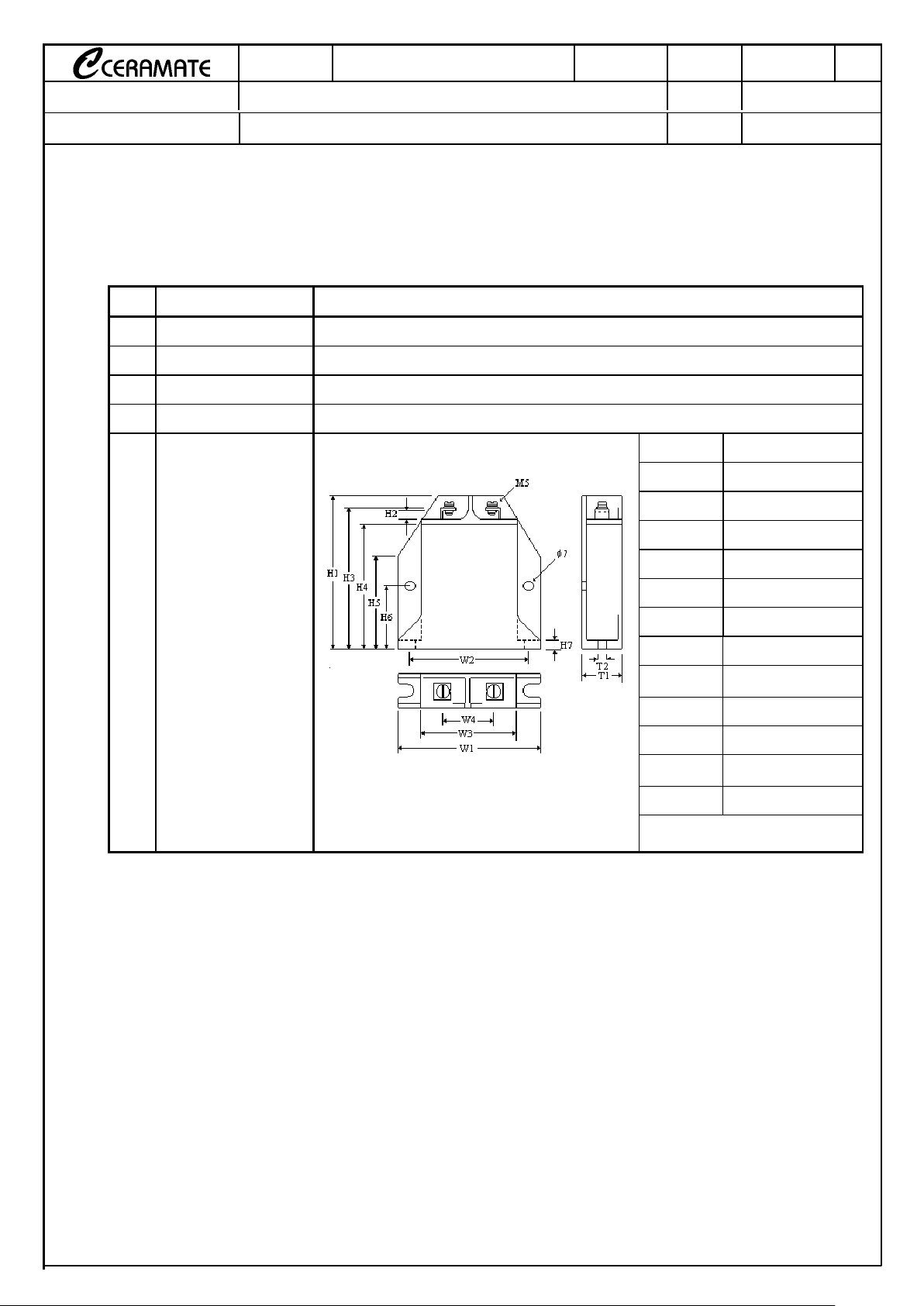
TYPE
GNR60B□□□
□□□□□□
□□□K
MODEL
PAGE 2/4
CITATION
DATE
Feb. 06, 2002
SUBJECT
QUALITY APPROVAL and STRUCTURE
REV.
B01
1. QUALITY SYSTEM APPROVAL
ISO9001 Certificate of approval No.97-HOU-AQ-1382
2. STRUCTURE
NO. ITEM DESCRIPTION
2.1 Main Material Zinc Oxide
2.2 Package Material Plastic
2.3 Marking GNR, Part number
2.4 Appearance Without dirt and crack, marking should be clear
H1(max.) 100.0
H2(mak.) 5.0
H3(max.) 92.0
H4(max.) 83.0
H5(max.) 45.0
H6(max.)
30.0
H7(max.)
5.0
T1(max.) 24.0
T2(max.) 7.0
W1(max.) 100.0
W2(max.) 86.0
W3(max.) 71.0
W4(max.) 40.0
2.5 Dimensions
Unit: mm
Page 3

TYPE
GNR60B□□□
□□□□□□
□□□K
MODEL
PAGE 3/4
CITATION
DATE
Feb. 06, 2002
SUBJECT
ELECTRICAL CHARACTERISTICS
REV.
B01
3. ELECTRICAL CHARACTERISTICS
N0. ITEM PERFORMANCE TEST METHODS
3.0 Standard Conditions
Unless otherwise specified, all tests are made
under environmental conditions as given below:
Temperature: 5〜35℃
Relative humidity: 45〜85 % RH
3.1
Maximum Allowable
Voltage
AC : **** Vrms
DC : **** V
Maximum continuous sine wave(RMS) or DC
voltage which may be applied.
3.2 Varistor Voltage V
1mA
: **** V
Voltage across the varistor measured at CmA DC.
3.3
Varistor Voltage
Temperature
Coefficient
0 〜 −−−−0.05 %/℃
V
CmA
at 85℃ - V
CmA
at 25℃ 1
V
CmA
at 25℃ 60
3.4
Max. Clamping
Voltage
*
**
* V at **** A
Peak voltage across the varistor with a specified
peak impulse current of 8× 20μs waveform.
3.5 Rated Power **** W
Maximum 50〜60Hz power which may be
loaded for 1,000 hrs at 85± 2℃ with
△V
CmA
/ V
CmA
≦± 10%.
The max. current within the varistor voltage
change of less than ± 10% when one impulse
current (8× 20μs) applied.
3.6
Withstanding Surge
Current
*
**
* A
The max. current with a varistor voltage change
of less than ± 10% when two times impulse
current (8× 20μs) are applied at intervals of 5
minutes.
3.7 Energy **** Joule
The max. energy absorbed with a varistor
voltage change of less than ± 10% when one
impulse(2ms) is applied.
3.8 Typical Capacitance **** pF
Capacitance shall be measured at 1 kHz± 10%,1
Vrms max. 0V bias and 20± 2℃
* See Page 4
×
×
100
Page 4

TYPE
GNR60B□□□
□□□□□□
□□□K
MODEL
PAGE 4/4
CITATION
DATE
Feb. 06, 2002
SUBJECT
ELECTRICAL CHARACTERISTICS
REV.
B01
MAXIMUM
ALLOWABLE
VOLTAGE
VARISTOR
VOLTAGE
CLAMPING
VOLTAGE
(MAX.)
RATED
WATTAGE
(MAX.)
SURGE
CURRENT
(8/20μμμμs)
MAXIMUM
ENERGY
(2ms)
Typical
Capacitance
Itm(A)
PART
NUMBER
AC
rms
(V) DC(V) (V) (V) Ip(A) (W)
1 TIME 2 TIMES
Wtm(joule) pF
60B330K 20 26 30
〜
36 65 120 86000
60B390K 25 31 35
〜
43 77 150 64000
60B470K 30 38 42
〜
52 93 190 55000
60B560K 35 45 50
〜
62 110 220 49000
60B680K 40 56 61
〜
75 135
100 0.35 20000 15000
250 43000
60B820K 50 65 74
〜
90 135 250 37000
60B101K 60 85 90
〜
110 165 300 30000
60B121K 75 100 108
〜
132 200 320 24500
60B151K 95 125 135
〜
165 250 380 20000
60B181K 115 150 162
〜
198 300
50000 40000
450 16500
60B201K 130 170 185
〜
225 340 490 15000
60B221K 140 180 198
〜
242 360 530 13250
60B241K 150 200 216
〜
264 395 570 12500
60B271K 175 225 247
〜
303 455 630 11000
60B301K 190 250 270
〜
330 505 650 10000
60B331K 210 275 297
〜
363 545 680 9000
60B361K 230 300 324
〜
396 595 730 8500
60B391K 250 320 351
〜
429 650 880 7500
60B431K 275 350 387
〜
473 710 950 7000
60B471K 300 385 423
〜
517 775 1000 6500
60B511K 320 410 459
〜
561 845 1100 6000
60B561K 350 460 504
〜
616 920 1200 5500
60B621K 385 505 558
〜
682 1025 1300 5000
60B681K 420 560 612
〜
748 1120 1500 4500
60B751K 460 615 675
〜
825 1240 1600 4000
60B781K 485 640 702
〜
858 1290 1650 3900
60B821K 510 670 738
〜
902 1355 1800 3700
60B911K 550 745 819
〜
1001 1500 2000 3300
60B951K 575 765 855
〜
1045 1570 2100 3200
60B102K 625 825 900
〜
1100 1650 2200 3000
60B112K 680 895 990
〜
1210 1815 2500 2700
60B122K 750 990 1155
〜
1320 1980 2700 2500
60B142K 880 1140 1310
〜
1540 2310 2400 2200
60B162K 1000 1280 1700
〜
1980 2640
500 1.6
70000 50000
2600 1900
 Loading...