

Page 1
No. Item
Continued on the following page.
Solder resist
Copper foil
c
d
b b
a
a
c
d
Solder resist
Copper foil
Operating
Temperature
1
Range
Rated Voltage
2
Appearance
3
Dimensions
4
Dielectric Strength
5
Insulation
6
Resistance
Capacitance
7
Q/
Dissipation Factor
8
(D.F.)
Capacitance
9
Temperature
Characteristics
Adhesive Strength
10
of Termination
Capacitance
Change
Temperature
Coefficent
Capacitance
Drift
Specifications
Temperature
Compensating Type
5C : –55 to +125°C
R7 : –55 to +125°C
R6 : –30 to +85°C
High Dielectric Type
See the previous pages
No defects or abnormalities
Within the specified dimensions
No defects or abnormalities
•
More than 10,000MΩ or 500Ω
F
(Whichever is smaller)
Within the specified tolerance
30pF min. : QU1000
30pF max. :
QU400+20C
C : Nominal
Char.
R7, R6
25V
0.025
max.
min.
16V
0.035
max.
10V
0.035
max.
6.3V
0.05
max.
Capacitance (pF)
Temp.
Within the
specified tolerance
(Table A)
Char.
R7
R6
Range
–55C°
to +125C°
–55C°
to +85C°
Reference
Temp
25°C
Cap.
Change
Within
T15%
Within the
specified tolerance
(Table A)
Within T0.2%
or T0.05pF
(Whichever is
larger.)
No removal of the terminations or other defect should occur.
GNMpp4 GNMpp2
Test Method
The rated voltage is defined as the maximum voltage which
may be applied continuously to the capacitor.
When AC voltage is superimposed on DC voltage, V
P-P
O-P
or V
whichever is larger, should be maintained within the rated
voltage range.
Visual inspection
Using calipers
No failure should be observed when 300% of the rated voltage
(5C) or 250% of the rated voltage (R7) is applied between the
terminations for 1 to 5 seconds, provided the charge/discharge
current is less than 50mA.
The insulation resistance should be measured with a DC
voltage not exceeding the rated voltage at 25°C and 75%RH
max. and within 2 minutes of charging.
The capacitance/Q/D.F. should be measured at 25°C at the
frequency and voltage shown in the table.
Char.
Item
Frequency
Voltage
5C R7
1T0.1MHz 1T0.1kHz
0.5 to 5Vrms
1.0T0.2Vrms
The capacitance change should be measured after 5 min. at
each specified temperature stage.
(1) Temperature Compensating Type
The temperature coefficient is determined using the capacitance measured in step 3 as a reference. When cycling the
temperature sequentially from step1 through 5, the capacitance
should be within the specified tolerance for the temperature
coefficient and capacitance change as Table A.
The capacitance drift is calculated by dividing the differences
between the maximum and minimum measured values in the
steps 1, 3 and 5 by the cap. value in step 3.
Step
1
2
3
4
5
Temperature (°C)
25T2
–55T3 (for 5C/R7), –30T3 (for F5)
25T2
125T3 (for 5C/R7), 85T3 (for F5)
20T2
(2) High Dielectric Constant Type
The ranges of capacitance change compared with the above
25°C value over the temperature ranges shown in the table
should be within the specified ranges.
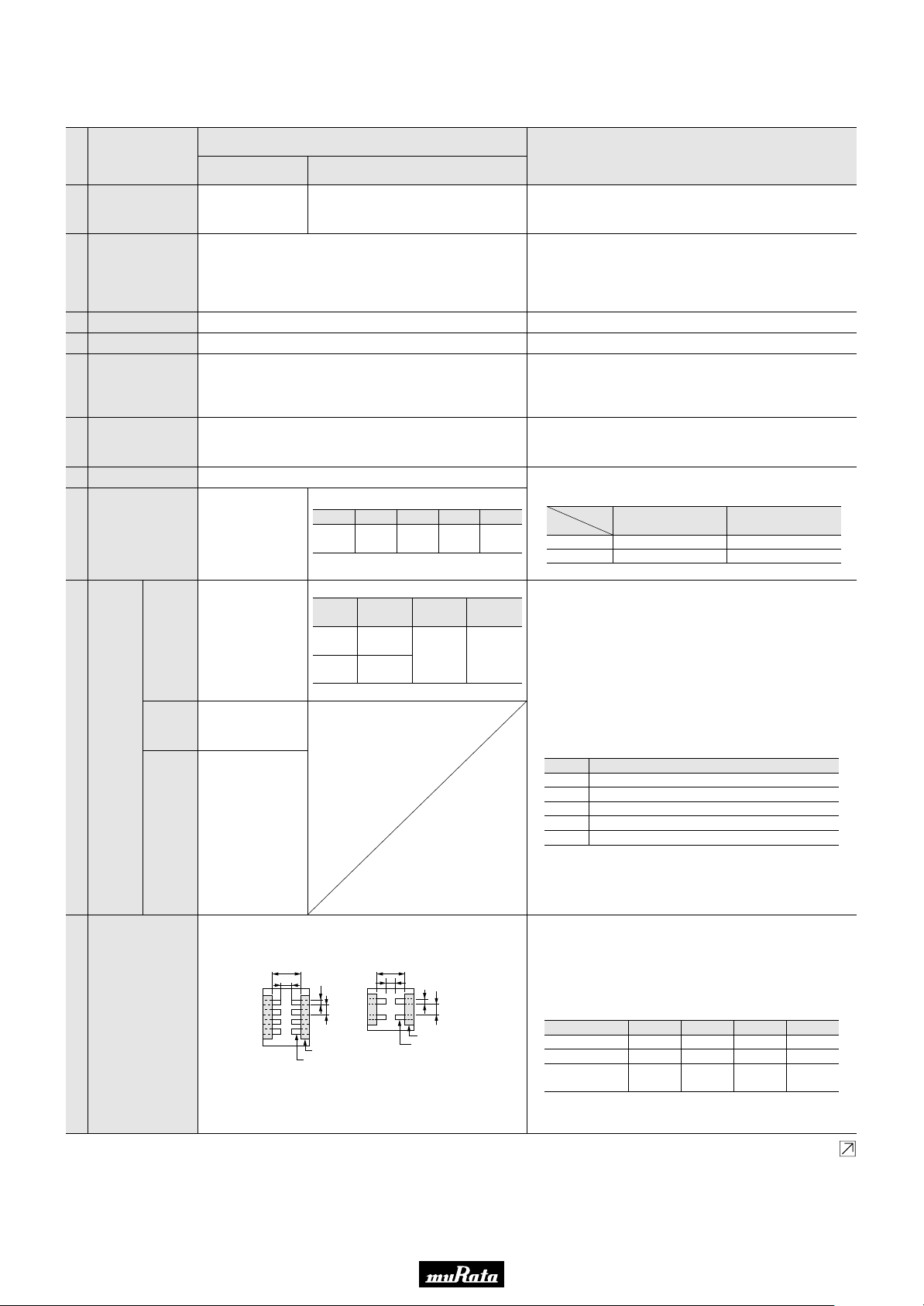
Solder the capacitor to the test jig (glass epoxy board) shown in
Fig.1 using a eutectic solder. Then apply 5N force in parallel with
the test jig for 10T1 sec.
The soldering should be done either with an iron or using the
reflow method and should be conducted with care so that the
soldering is uniform and free of defects such as heat shock.
Type a b c d
GNM1M2
GNM212
GNM214
GNp314
0.5
0.4
0.6
0.8
1.6
1.8
2.0
2.5
0.32
0.15
0.25
0.4
0.32
0.5
0.25
0.4
(in mm)
Fig. 1
,
Page 2
Continued from the preceding page.
Continued on the following page.
No. Item
100
1.0
5.0
b
a
40
c
d
100
1.0
5.0
b
a
40
c
d
Capacitance meter
Flexure : V1
20
50
R230
Pressurizing
speed : 1.0mm/sec.
Pressurize
45 45
Vibration
11
Resistance
Deflection12
Appearance
Capacitance
Q/D.F.
Specifications
Temperature
Compensating Type
High Dielectric Type
No defects or abnormalities
Within the specified tolerance
30pF min. : QU1000
30pF max. :
QU400+20C
C : Nominal
Char.
R7, R6
25V
0.025
max.
min.
16V
0.035
max.
Capacitance (pF)
No cracking or marking defects should occur
#GNMpp4 #GNMpp2
10V
0.035
max.
6.3V
0.05
max.
t=0.8mm
Test Method
Solder the capacitor to the test jig (glass epoxy board) in the
same manner and under the same conditions as (10). The
capacitor should be subjected to a simple harmonic motion
having a total amplitude of 1.5mm, the frequency being varied
uniformly between the approximate limits of 10 and 55Hz. The
frequency range, from 10 to 55Hz and return to 10Hz, should
be traversed in approximately 1 minute. This motion should be
applied for a period of 2 hours in each 3 mutually perpendicular
directions (total of 6 hours).
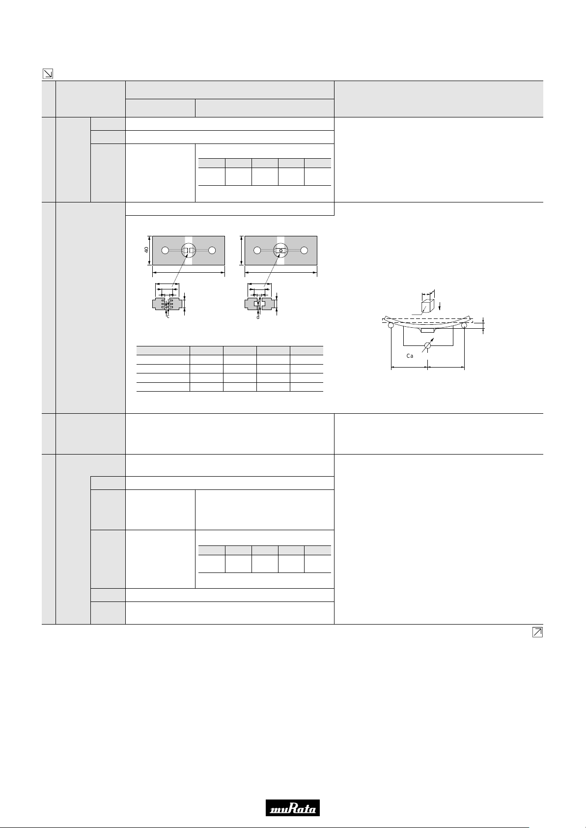
Solder the capacitor on the test jig (glass epoxy board) shown
in Fig. 2 using a eutectic solder.
Then apply a force in the direction shown in Fig. 3 for 5T1 sec.
The soldering should be done either with an iron or using the
reflow method and should be conducted with care so that the
soldering is uniform and free of defects such as heat shock.
Solderability of
13
Termination
Resistance to
Soldering Heat
14
Appearance
Capacitance
Change
Q/D.F.
I.R.
Dielectric
Strength
Type a b c d
GNM1M2
GNM212
GNM214
GNp314
2.0T0.05
2.0T0.05
2.0T0.05
2.5T0.05
0.5T0.05
0.6T0.05
0.7T0.05
0.8T0.05
0.32T0.05
0.5T0.05
0.3T0.05
0.4T0.05
0.32T0.05
0.5T0.05
0.2T0.05
0.4T0.05
(in mm)
Fig. 2
75% of the terminations are to be soldered evenly and
continuously.
The measured and observed characteristics should satisfy the
specifications in the following table.
No marking defects
Within T2.5%
or T0.25pF
(Whichever is
R7, R6 : Within T7.5%
larger)
30pF min. : QU1000
30pF max. :
QU400+20C
C : Nominal
Char.
R7, R6
25V
0.025
max.
min.
16V
0.035
max.
10V
0.035
max.
6.3V
0.05
max.
Capacitance (pF)
•
More than 10,000MΩ or 500Ω
F (Whichever is smaller)
No failure
Fig. 3
Immerse the capacitor in a solution of ethanol (JIS-K-8101) and
rosin (JIS-K-5902) (25% rosin in weight proportion). Preheat at
80 to 120°C for 10 to 30 seconds. After preheating, immerse in
eutectic solder solution for 2T0.5 seconds at 230T5°C.
Preheat the capacitor at 120 to 150°C for 1 minute. Immerse
the capacitor in a eutectic solder solution at 270T5°C for
10T0.5 seconds. Let sit at room temperature for 24T2 hours
(temperature compensating type) or 48T4 hours (high dielectric
constant type), then measure.
• Initial measurement for high dielectric constant type
Perform a heat treatment at 150+0/-10°C for one hour and
then let sit for 48T4 hours at room temperature.
Perform the initial measurement.
Page 3

Continued from the preceding page.
No. Item
Continued on the following page.
Temperature
Cycle
15
Humidity Steady
State
16
Humidity Load
17
Appearance
Capacitance
Change
Q/D.F.
I.R.
Dielectric
Strength
Appearance
Capacitance
Change
Q/D.F.
I.R.
Dielectric
Strength
Appearance
Capacitance
Change
Q/D.F.
I.R.
Dielectric
Strength
Specifications
Temperature
Compensating Type
High Dielectric Type
The measured and observed characteristics should satisfy the
specifications in the following table.
No marking defects
Within T2.5%
or T0.25pF
(Whichever is
R7, R6 : Within T7.5%
larger)
30pF min. : QU1000
30pF max. :
QU400+20C
C:Nominal
Char.
R7, R6
25V
0.025
max.
min.
16V
0.035
max.
10V
0.035
max.
6.3V
0.05
max.
Capacitance (pF)
•
More than 10,000MΩ or 500Ω
F (Whichever is smaller)
No failure
The measured and observed characteristics should satisfy the
specifications in the following table.
No marking defects
Within T5%
or T0.5pF
(Whichever is
R7, R6 : Within T12.5%
larger)
30pF and over :
QU350
10pF and over,
30pF and below:
QU275+5C/2
10pF and below :
Char.
R7, R6
25V
0.05
max.
min.
16V
0.05
max.
10V/6.3V
0.05
max.
QU200+10C
C : Nominal
Capacitance (pF)
More than 1,000MΩ or 50Ω
•
F (Whichever is smaller)
No failure
The measured and observed characteristics should satisfy the
specifications in the following table.
No marking defects
Within T7.5%
or T0.75pF
(Whichever is
R7, R6 : Within T12.5%
larger)
30pF and over :
30pF and below :
QU200
QU100+10C/3
Char.
R7, R6
25V
max.
0.05
min.
16V
0.05
max.
10V/6.3V
0.05
max.
C : Nominal
Capacitance (pF)
More than 500MΩ or 25Ω
•
F (Whichever is smaller)
No failure
Test Method
Fix the capacitor to the supporting jig in the same manner and
under the same conditions as (10). Perform the five cycles
according to the four heat treatments listed in the following
table. Let sit for 24T2 hours (temperature compensating type)
or 48T4 hours (high dielectric constant type) at room
temperature, then measure.
Step 1 2 3 4
Temp. (°C)
Time (min.)
Min.
Operating
Temp. +0/–3
Room
Temp.
30±3 2 to 3 30±3 2 to 3
Max.
Operating
Temp. +3/–0
Room
Temp.
• Initial measurement for high dielectric constant type
Perform a heat treatment at 150+0/-10°C for one hour and
then let sit for 48T4 hours at room temperature.
Perform the initial measurement.
Sit the capacitor at 40T2°C and 90 to 95% humidity for 500T12
hours.
Remove and let sit for 24T2 hours (temperature compensating
type) or 48T4 hours (high dielectric constant type) at room
temperature, then measure.
Apply the rated voltage at 40T2°C and 90 to 95% humidity for
500T12 hours.
Remove and let sit for 24T2 hours(temperature compensating
type) or 48T4 hours (high dielectric constant type) at room
temprature, then muasure.
The charge/discharge current is less than 50mA.
Page 4

Continued from the preceding page.
Specifications
No. Item
High Temperature
Load
Appearance
Capacitance
Change
Temperature
Compensating Type
High Dielectric Type
The measured and observed characteristics should satisfy the
specifications in the following table.
No marking defects
Within T3%
or T0.3pF
(Whichever is
R7, R6 : Within T12.5%
larger)
18
Q/D.F.
30pF and over :
QU350
10pF and over,
30pF and below :
QU275+5C/2
10pF and below :
Char.
R7, R6
25V
max.
0.04
min.
16V
0.05
max.
10V/6.3V
0.05
max.
QU200+10C
C : Nominal
Capacitance (pF)
•
I.R.
More than 1,000MΩ or 50Ω
F (Whichever is smaller)
Table A
Char.
5C
Nominal Values
(ppm/D) Note 1
0T30
Note 1 : Nominal values denote the temperature coefficient within a range of 25 to 125D.
Y55D
Max. Min.
Test Method
Apply 200% of the rated voltage for 1000T12 hours at the
maximun operating temperature T3°C. Let sit for 24T2
hours(temperature compensating type) or 48T4 hours(high
dielectric constant type) at room temperature, then measure.
The charge/discharge current is less than 50mA.
• Initial measurement for high dielectric constant type.
Apply 200% of the rated DC voltage for one hour at the
maximun operating temperature T3°C. Remove and let sit for
48T4 hours at room temperature.Perform initial measurement.
Capacitance Change from 25D (%)
Y30D Y10D
Max. Min.
Max. Min.
0.250.400.58
Y0.11Y0.17Y0.24
 Loading...