

Page 1
20
21
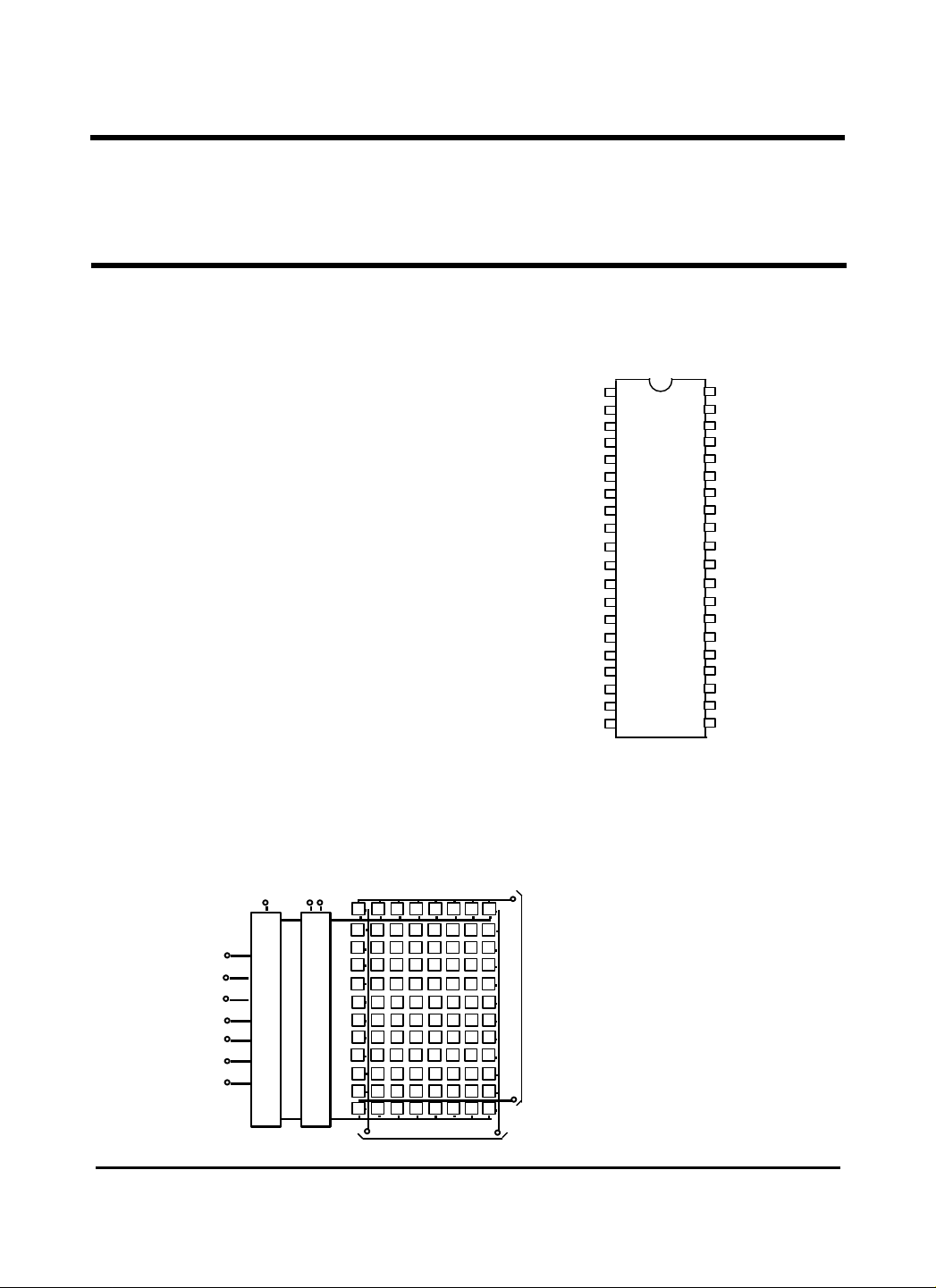
7 TO 96 DECODER
LATCHES
0
7
Input (
0~11)
GM62093A
GM62093A
12×8 CROSSPOINT SWITCH
WITH CONTROL MEMORY
Description
The GM62093A contains a 12×8 array of
crosspoint together with a 7 to 96 Line decoder
and latch circuits. The GM62093A employs
LG’s advanced high voltage CMOS process
technology. It provides extra low operating
current and low power dissipation.
Anyone of the 96 switchs can be addressed by
selecting the ap-propriate 7 input bits. The
selected turned on or off by applying a logical
one or zero to the data in and the strobe input
at logical one. A reset signal can be used to
turn off all the switches together when is
switched at logical one. The GM62093A is
avail-able in a 40 lead dual in-line plastic and
ceramic package.
Feature
• CMOS 12×8 Cross Point Switch with
Control Memory
• Low On Resistance
• Internal Control Latches
• ∆Ron 15Ω Max
• Less Than 1% Total Distortion at 0 dbm
• Extra Low Operating Current
• Extra Low Cross-Talk Between Any Two
Switches
• Standard CMOS Noise Immunity
• TTL Compatible Input
Block Diagram
ADDRESS
AX0
AX1
AX2
AX3
AY0
AY1
AY2
STROBE
DATA RESET
1
96
8
88 95
8
Y0 Y7 Yi Input (i=0~7)
Pin Configuration
(Top View)
Application
• PBX Systems
• Mobile Radio
• Test Eqiepment Instrumentation
• Analog/ Digital Multiplexer
X0
X11
1
Y3
1
AY2
2
RESET
3
AX3
4
AX0
5
NC
6
NC
7
X6
8
X7
X8
X9
X10
X11
NC
Y7
NC
Y6
STROBE
Y5
V
SS
I=
Xii
9
10
11
12
13
14
15
16
17
18
19
V
40
DD
Y2
39
DATA
38
Y1
37
NC
36
Y0
35
NC
34
X0
33
32
X1
31
X2
30
X3
29
X4
28
X5
27
NC
26
NC
25
AY1
24
AY0
23
AX2
AX1
22
Y4
Page 2
GM62093A
C70
°
=
=
=
µ
−
±
=
±
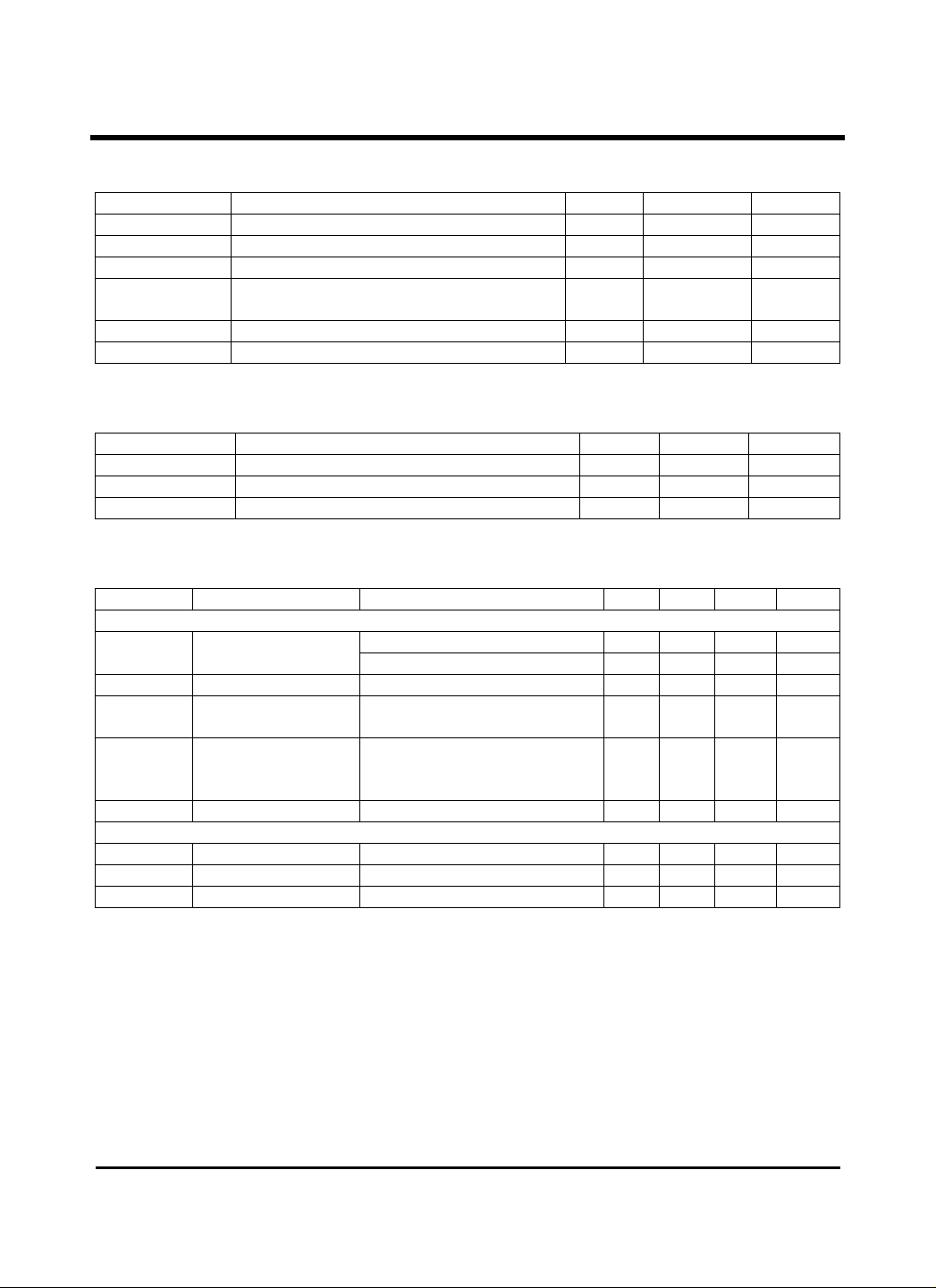
Absolute Maximum Rating
SYMBOL PARAMETER MIN MAX UNIT
V DC Supply Voltage -0.5 18 V
DD
V Input Voltage Range -0.5 V+0.5 V
IN
I DC Input current ±10 mA
IN
P(P-DIP)
(C-DIP)
T Operation Temperature Range 0 70 C°
OPR
T Storage Temperature Range -65 150 C°
STG
Power Dissipation 0.6
1
Recommended Operating Range
SYMBOL PARAMETER MIN MAX UNIT
V DC Supply 8 16 V
DD
V Input Voltage Range 0
IN
T Operation Temperature Range 0 70 C°
OPR
V V
DD
W
Static Electrical Characteristics: ( C0T
SYMBOL PARAMETER TEST CONDITION MIN TYP MAX UNIT
CROSS POINT
I Quiescent Supply
DD
Ron On Resistance V5.3V
Ron Ron Difference Between
Asc Analog Signal Capability V14V
I Off Leakage All Switch off V=V=0 to V 500
LOFF
CONTROLS
V Input Low Voltage 0.8 V
IL
V Input High Voltage 2.4 V
IH
I Input Leakage 0V
LEAK
Current
Any Two Switchs
°= to
A
All Digital Input at Vss or VDD 100 Aµ
All Digital Input at 2.4 V 7 15 mA
DD
15 Ω
DD
is
I(thru S/W)= A100
IN
and I(thru S/W)=10mA 65 Ω
All Switchs On
V14V
and
to
V 500
DD
, V14V
= )
CC
13.96 14.0 V
nA
nA
2
Page 3
°
=
=
GM62093A
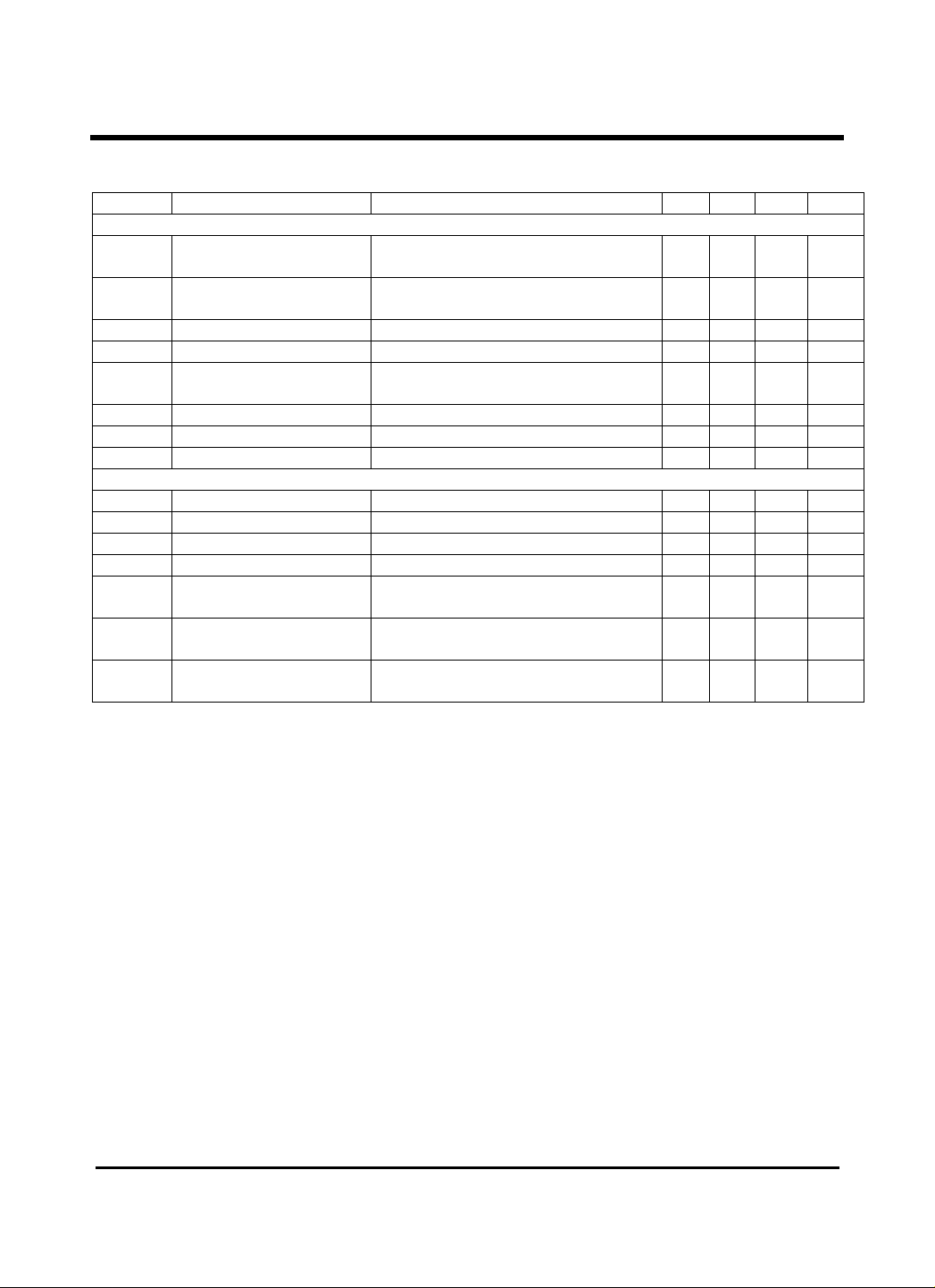
Dynamic Electrical Characteristics : ( C25T
SYMBOL
CROSS POINT
t
P
f
RES
Feedthrough (All S/W’ s Off) V5V,k1R
C Capacitance (XN to Ground) Switch Off 20 pF
X
C Capacitance (YN to Ground) Switch Off 30 pF
Y
C Digital Input Capacitance 5 pF
DI
CONTROL
t Strobe to Switch Delay nS20tt,k1R
DS
t Data to Switch Delay nS20tt,k1R
DD
t Address to Switch Delay nS20tt,k1R
DA
t Reset to Switch Delay nS20tt,k1R
DR
t
SD
t
SA
t
HD
t
HA
t
SW
t
RW
PARAMETER TEST CONDITION MIN TYP MAX UNIT
Propagation Delay Time V5V,k1R
Frequency Response
[20log(VOUT/VIN)=-3dB]
Sine Wave Response(Distortion)
Crosstalk Between Any
Two Channels
Data Setup Time
Address Setup Time
Data Hold Time
Address Hold Time
Minimum Strobe Pulse Width
Minimum Reset Pulse Width
Functional Description
The GM62093A contains a 12×8 array of
analog switches, each with a latch to maintain
its on(closed)or off(opened) state.
Seven ADDRESS lines(AX0~AX3,
AY0~AY2) are provided to address any one of
the 96 switches.
After any one of the switches is selected, the
A
DCL
V2V =
PPIS
DCL
V2V = , F3C
PPIS
DCL
DCL
LS
, pF50=C
L
=Ω=
V5V,k1R
=Ω=
=
pL
V5V,k1R
=Ω= , MHz1f,V2V
=Ω= KHz10=f,V2=V
Ω=Ω= k1R,50R
, KHz1=f,V2=V
==Ω= 160 nS
frL
==Ω= 180 nS
frL
==Ω= 200 nS
frL
==Ω= 200 nS
frL
nS20tt,k1R
==Ω= 30 nS
frL
nS20tt,k1R
==Ω= 30 nS
frL
nS20tt,k1R
==Ω= 200 nS
frL
, V14V
DD
== 1 %
PPIS
PPIS
PPIS
-110 -95 dB
)
30 NS
40 MHz
-80 dB
DATA pin may be held high to turn the switch
on, or low to turn it off.
Finally a positive pulse to the STROBE pin
initiates the ac-tion determined by the
ADDRESS and DATA pins. All 96 switches
can be turned off by forcing the RESET pin
high.
3
Page 4
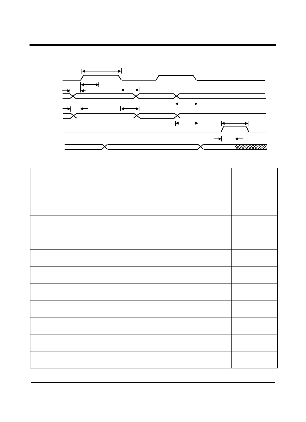
Timing Diagram
STROBE
ADDRESS
DATA
RESET
SW
SA
DS
HA
SDtHDtDA
DDtDRtRW
GM62093A
t
t
t
t
t
ANALOG
Truth Table
Address
AX0 AX1 AX2 AX3 AY0 AY1 AY2
0
1
0
1
0
1
0
1
0
1
0
1
0
↓
1
0
↓
1
0
↓
1
0
↓
1
0
↓
1
0
↓
1
0
↓
1
A =0110, 1110, 0111 and 1111 and not allowed
X
0
0
1
1
0
0
0
0
1
1
0
0
0
↓
0
0
↓
0
0
↓
0
0
↓
0
0
↓
0
0
↓
0
0
↓
0
0
0
0
0
1
1
0
0
0
0
1
1
0
↓
1
0
↓
1
0
↓
1
0
↓
1
0
↓
1
0
↓
1
0
↓
1
0
0
0
0
0
0
1
1
1
1
1
1
0
↓
1
0
↓
1
0
↓
1
0
↓
1
0
↓
1
0
↓
1
0
↓
1
0
0
0
0
0
0
0
0
0
0
0
0
1
↓
1
0
↓
0
1
↓
1
0
↓
0
1
↓
1
0
↓
0
1
↓
1
0
0
0
0
0
0
0
0
0
0
0
0
0
↓
0
1
↓
1
1
↓
1
0
↓
0
0
↓
0
1
↓
1
1
↓
1
0
0
0
0
0
0
0
0
0
0
0
0
0
↓
0
0
↓
0
0
↓
0
1
↓
1
1
↓
1
1
↓
1
1
↓
1
t
Connections
X0-Y0
X1-Y0
X2-Y0
X3-Y0
X4-Y0
X5-Y0
X6-Y0
X7-Y0
X8-Y0
X9-Y0
X10-Y0
X11-Y0
X0-Y1
↓ ↓
X11-Y1
X0-Y2
↓ ↓
X11-Y2
X0-Y3
↓ ↓
X11-Y3
X0-Y4
↓ ↓
X11-Y4
X0-Y5
↓ ↓
X11-Y5
X0-Y6
↓ ↓
X11-Y6
X0-Y7
↓ ↓
X11-Y7
4
Page 5

Test circuit and Characteristics.
4
4 8 12 16
5V
l CROSSTALK vs. FREQUENCY
OUT
V
5
OUT
(V)
dB
-80
-90
-100
-110
-120
-130
16
12
8
0
Fig.1-Crosstalk
l TEST CIRCUIT
V
IN
50Ω
S/W ON
1KΩ
1KΩ
S/W ON
V
1KΩ
5V
5V
5V
V14=V
DD
V =2Vp-p
IN
l RESULT
Fig.2 –analog signal capability(Vin vs. Vout)
l TEST CIRCUIT
V
DD
V
IN
S/W
ON
V
OUT
IN
CONTROL
V20~0=V
V5=V
10
GM62093A
2
10
10
f(KHz)
16=DDV
12=DDV
8=DDV
4=DDV
(V)INV
3
Page 6
50 40
6 8 10 12 14 16
l RESULT
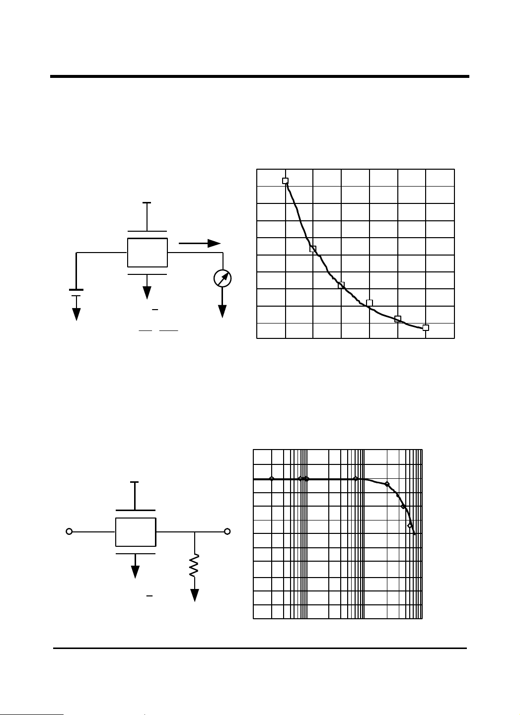
Fig.3-Ron measurement
l TEST CIRCUIT
V
DD
R
ON
Ω
60
S.W
ON
10mA
3.5V
+ VÄ
V
V
R
ON
˜˜
==
mA
I
10
ON
30
20
VV
CONTROL
DD
5=
VV
18~6=
l BANDWIDTH
Fig.4-Frequency response. (-3dB point: ABOUT 45MHz)
l TEST CIRCUIT
dB
0
-2
V
IN
S/W
ON
15KΩ
VVDD14=
VIN=2Vp-p
-4
V
OUT
-6
-8
-10
1
10
GM62093A
2
10
f(MHz)
V
DD
6
 Loading...