

Page 1
LED Lamps
Series
❑ 43 Series
Ype
‘
‘ED
■ Model No.
GL3UR43 Red (Super-luminosity)
GL3LR43 Red (High-luminosity)
GL3TR43 Red (High-luminosity)
GL3PR43 Red
GL3HD43 Red
GL3HS43 Sunset orange
GL3HY43 Yellow
GL3EG43 Yellow-green
GL3KG43 Green
Features
2.
Colored transparency lens type
3.
Wide viewing angle
■ Absolute Maximum Ratings
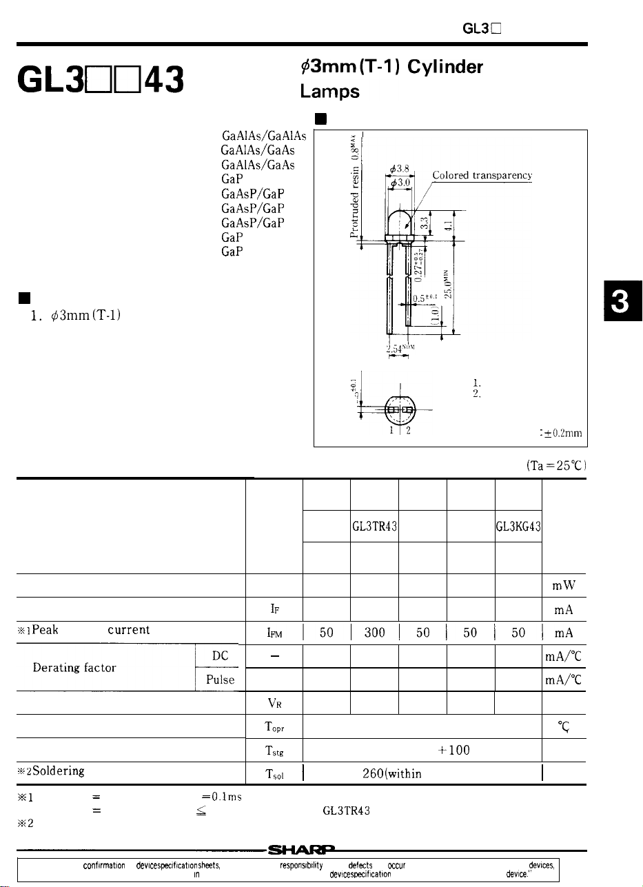
Outline Dimensions
,
0
. . . . .
12
GL3UR43 GL3LR43
GL3PR43
(Unit: mm)
Pin connections
Anode
Cathode
Unspecified tolerance
GL3HD43 GL3EG43
fO.2mm
Parameter
Power dissipation
Continuous forward current
forward current
Reverse voltage
Operating temperature
Storage temperature
Duty ratio
Duty ratio
“In the absence of con f!rmotlon by
shown m catalogs, data books, etc. Contact SHARP
temperature
1/10 , Pulse width
1/16 , Pulse width
spsctftcatlon sh&ts, SHARP takes no responstb(l!ty for any
Symbol
P 75
30
0.40 0.67 0.13
—
O.lms
lms for GL3LR43 and
order to obtain the latest version of the dev!ce
0.67
4
110
50
4.00
5
that
23 84
10
0.67 0.67 0.67
5
–25 to +85
–25 to +100
5 seconds)
m equipment using any of SHARPS dev[ces,
sheets before using any SHARPS
GL3HS43
GL3HY43
30 30
0.40
5 5
Unit
84 mW
0.40 mA~C
v
“c
“c
55
Page 2
LED Lamps
■
Characteristics
Parameter
Forward voltage
Luminous intensity
Peak emission wavelength
Spectrum radiation bandwidth
Reverse current
Terminal capacitance
Response frequency
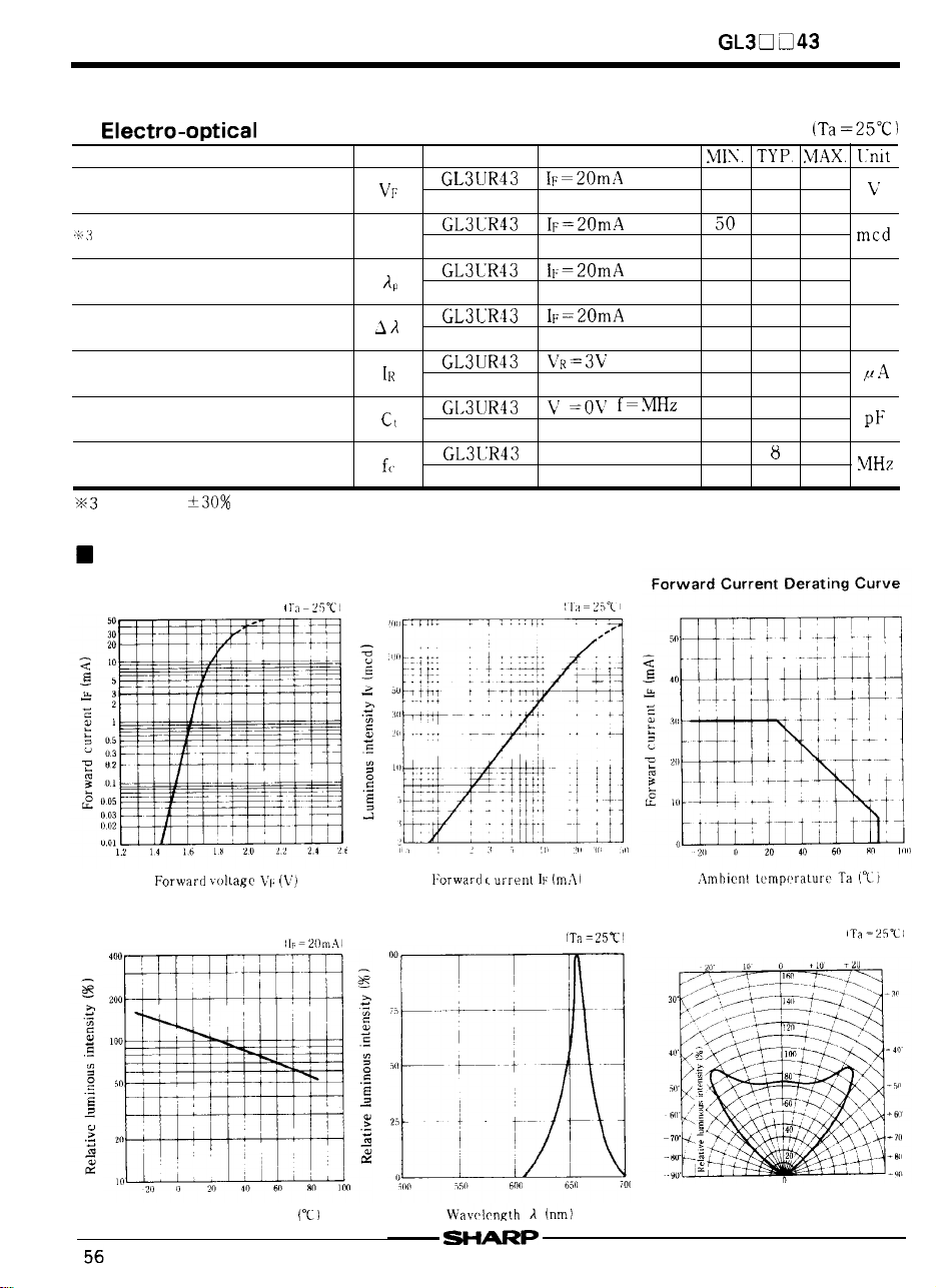
Characteristics Diagrams
Forward Current vs.
Forward Voltage
GL3UR43 (Red)
Symbol
Model No. Conditions
I\
Luminous Intensity vs.
Forward Current
Series
—
185
2.5
–
100
660
–
nm
—
20
-
nm
—
100
f=MHz
–
–
—
25
–
–
(V)
Relative Luminous Intensity vs.
Ambient Temperature
Ambient temperature Ta
Spectrum Distribution
(m,!)
Radiation Diagram
Page 3

LED Lamps
GL3LR43 (Red) / GL3TR43 (Red)
■
Characteristics
Parameter
Forward voltage
intensity
Peak emission wavelength
Spectrum radiation bandwidth
Reverse current
Terminal capacitance
Response frequency
Tolerance:
Characteristics Diagrams
Forward Current vs.
Forward Voltage
Luminous Intensity vs.
Forward Current
Model No,
GL3LR43
GL3TR43
GL3LR43
GL3TR43
GL3LR43
GL3TR43
GL3TR43
GL3LR43
GL3TR43
GL3TR43
GL3LR43
GL3TR43
Conditions
V=OV
–
–
,
❑ 43 Series
(Ta =25°C )
MIN.
—
1,75 2.2
1.75 2.2
40
20
660
660
20
20
—
30
8
8
–
– ‘cd
–
– ‘m
–
– ‘m
10
10
– ‘F
–
–
20
10
—
—
— —
–
MHz –
—
Forward Current Derating Curve
Unit
v
Forward
Relative Luminous Intensity vs.
Ambient Temperature
u
“
“
temperature Ta
(v)
-21)m II
,M
I
10
Iii iii
Spectrum Distribution
I
Forward current
Wavelength
(nm )
temperature, Ta (“C)
Radiation Diagram
=25-L
Page 4

LED Lamps
Parameter Symbol
Forward voltage
Peak emission wavelength
Spectrum radiation bandwidth
Reverse current
Terminal capacitance
Response frequency
Tolerance:
■
Characteristics Diagrams
Forward Current vs.
Forward Voltage
Characteristics
GL3PR43 (Red) / GL3HD43 (Red)
Model No.
GL3PR43
GL3HD43
GL3PR43
GL3HD43
GL3PR43
GL3HD43
GL3PR43
GL3HD43
GL3PR43
GL3HD43
GL3PR43
GL3HD43
GL3PR43
GL3HD43
Luminous Intensity vs.
Forward Current
Conditions
V=OV
V=OV
–
–
❑
43 Series
MIN. TYP. MAX.
—
1.9 2.3
—
2.0 2.8
1.0
3.0 –
..” -
1
—
695 –
—
635 – ‘m
Unit
–
1
1
– ‘m
— —
10
10
Forward Current Derating Curve
–
–
—
—
20
–
–
4
–
4
–
.
L
L
.
Forward voltage
Relative Luminous Intensity vs.
Ambient Temperature,
400
,0”
50
.
_2(, ,, ~,,
I
,
u
1
. .
(V)
60
,
100
Forward current
Spectrum Distribution
Wavelength
(rim)
20
10
0
–20 O 20 40 60 80 10II
Ambient temperature Ta (“C
Radiation Diagram
-30
60
70
80
90
+ 3V
+ 50
+
+
58
Page 5

LED Lamps
GL3HS43 (Sunset orange) / GL3HY43 (Yellow)
■
Parameter
Forward voltage
intensity
Peak emission wavelength
Spectrum radiation bandwidth
Reverse current
Terminal capacitance
Response frequency
Tolerance:
■
Characteristics Diagrams
Forward Current vs.
Forward Voltage
Characteristics
Symbol
Model No.
GL3HS43
GL3HY43
GL3HS43
Iv
GL3HY43
GL3HS43
GL3HY43
GL3HS43
GL3HY43
GL3HS43
GL3HS43
GL3HY43
50
30
10
GL3HS43
GL3HY43
I
fc
Luminous Intensity vs.
Forward Current
20
Conditions
V=OV f=lMHz
–
–
MIN.
–
TYP. MAX,
—
—
7,0
7.0
—
610
—
585
—
—
— —
—
–
– ,
—
—
❑ 43 Series
Unit
2.0 2,8
2.0 2.8
–
25
– ‘cd
25
–
– ‘m
35
–
30
–
‘m
—
10
‘Hz
Forward voltage VF (V)
Relative Luminous Intensity vs.
Ambient Temperature
c
–20 0 20
Ambient temperature Ta (“C)
m
1, 1,
0.51
05123510
Spectrum Distribution
0
,W
551,
I
1 1
Forward current IF (mA)
Wavelength
(rim)
1
1 1
J
20
50
Ambient temperature Ta (“C)
Radiation Diagram
–20’ –10 0
–40
70
;,,,
=
+
+
+50
+70
59
Page 6

LED Lam~s
GL3EG43 (Yellow-green) / GL3KG43 (Green)
■
Parameter
Forward voltage
Lumlno”s
Peak emission wavelength
Spectrum radiation bandwidth
Reverse current
Terminal capacitance
Response frequency
Characteristics
■ Characteristics Diagrams
Forward Current vs.
Forward Voltage
Symbol
Model
GL3EG43
GL3KG43
GL3EG43
GL3KG43
GL3EG43
GL3KG43
GL3EG43
GL3KG43
GL3EG43
GL3KG43
GL3EG43
GL3KG43
GL3EG43
GL3KG43
Luminous Intensity vs.
Forward Current
Conditions
V=OV
V=OV f=lMHz
–
MHz
–
Forward Current
50
GL3D
❑ 43 Series
MIN. TYP.
—
2
10
25 –
8.0
20
—
565 –
—
555 –
30
—
25
—
—
—
–
4(I
–
4
—
MAX.
2.8
2.8
–
–
–
10
10
–
–
–
–
‘cd
nm
‘m
Curve
0,05
Forward V[)[tage
Relative Luminous Intensity vs.
Ambient Temperature
.
E
Ambient tempc!rature Ta
,
,
I
,
L-
Spectrum Distribution
Wavelength
30
.
$
10
0
411
Ambient temperature
Radiation Diagram
I
60
 Loading...