

Page 1
GI-7b/GI-70b/GI-7bT
Microwave Triode
The GI-7b, GI-70b and GI-7bT microwave triode operates as an oscillator or an amplifier in
continuous-wave or pulsed mode with anode modulation in the centimetric and decimetric
wavelength ranges. The GI-7"b" is available in two variants differing in the type of cooling:
the GI-7b with a heat sink for forced air cooling and the GI-70b with no heat sink for other
systems of cooling. The GI-7b is physically identical to the GI-6b and GS-9b, although there
are electrical differences. The GI-7bT comes with heat sink only, is more shock- and
vibration-proof, and has a larger ceramic structure. It is designed to be used in Tanks. The
"bT" varies in a few parameters from the "b", and these variations are noted in the tables
below. As with most Russian power triodes, the heat sink on the GI-7b & GI-7bT is
removable.
NOTE: Myriad tests have been conducted regarding the use of this tube for PAs at 23cm. It
is possible to derive a stable output of of up to approximately 250 W from a single tube GI7B
cavity PA, and designs for such PAs can be found on this web site. Even with outstanding
cooling, higher powers result in severe thermal drift problems. The most forgiving design is
by OK1KIR, because it uses a 1/4 w.l. anode cavity which is quite broadbanded compared
with the 3/4 w.l. cavities normally used. Even the extensive additional cooling measures
used in the OK1KIR design do not solve the thermal drift problems. Additionally, this design
will not accept the GI7BT due to physical limitations imposed by internal cavity dimensions.
In short, the GI7's internal dimensions are simply too big (too large in terms of electrical
wave length) to allow this tube to be used effectively at 23cm. The GI7 IS, however, well
suited for use in single and multiple-tube PAs from HF through 70cm, and designs for such
PAs are also on this web site (with more added as found!).
GENERAL
Cathode: indirectly heated, dispenser, oxide-coated.
Envelope: metal-ceramic.
Cooling: 24 m3/hr forced air (GI-7bT; 27 m3/hr). For 350W dissipation, 40 m3/hr is required by all!
Height, mm, at most:
with heat sink: 110.5
without heat sink: 97
Diameter, mm, at most:
with heat sink: 65
without heat sink: 36.3+
Mass, gm, at most:
with heat sink: 330
without heat sink: 170
Page 2
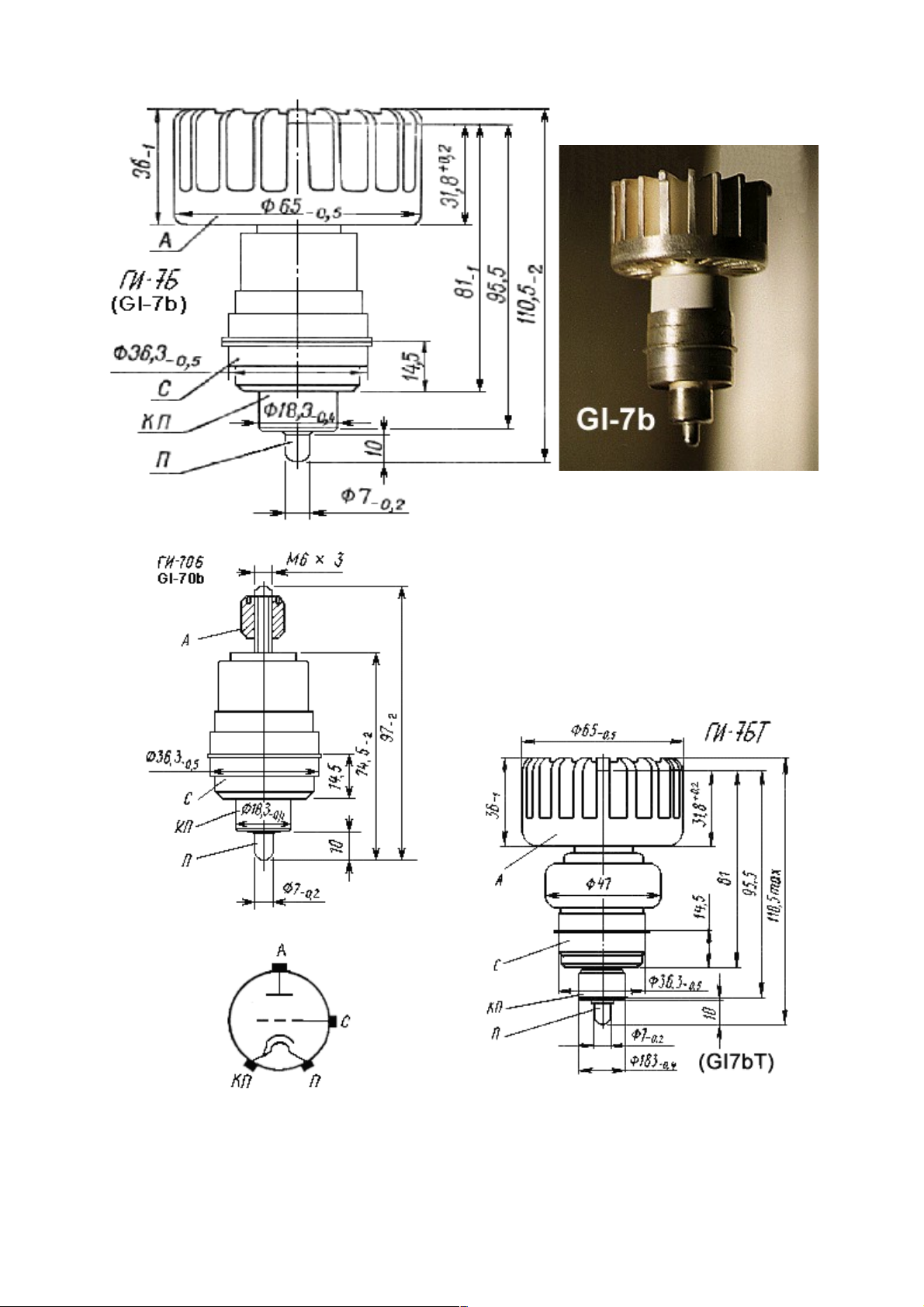
A - anode; C - grid; KP - cathode and heater;
P - heater
Note the physical difference of the GI-7bT
compared to the GI-7b is in the "ceramic" portion of
the body; 47mm diameter instead of a bit less than
36mm!
Page 3
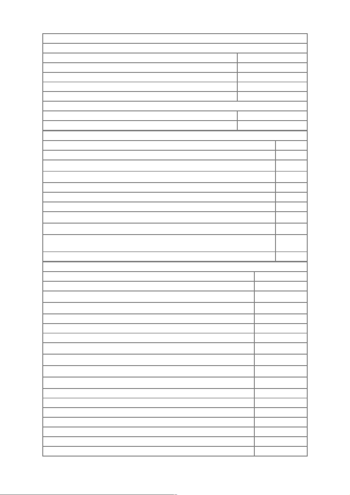
OPERATING ENVIRONMENTAL CONDITIONS
Vibration loads:
frequency, Hz 5-600
acceleration, m/s² 59
Multiple loads with acceleration, m/s² 342
Single impacts with acceleration, m/s² 1,465
Linear loads with acceleration, m/s² 490
Ambient Conditions:
Temperature, °C -60 to +100
Relative humidity at up to +40 °C, % 95-98
NOMINAL ELECTRICAL PARAMETERS
Heater voltage, V 12.6
Heater current, A 1.925
Mutual conductance (Va = 1.2 kV, Ia = 150 mA, change in Vg = 1V), mA/V:
>23
Operating point (negative Vg with Va = 1.3KV, Ia = 150mA), V:
10
input capacitance, pF: 11.1
output capacitance, pF: 4.6
transfer capacitance, pF: 0.075
Warm up time (Va = 400V), at most
90
Output, CW operation (Va =1.05KV, Ia =300mA, wavelength 18.5 cm), W (GI7b / GI7bT):
>30 / >40
Output in pulsed operation (at peak Va = 9KV, Ia = 7.5A, wavelength 10 cm,
1/pulse duty factor 1,400-150, pulse duration 3-10 ÷s), KW (GI7b / GI7bT):
>11 / >12
Designed Tube Life (hours) >650
ELECTRICAL PARAMETER LIMITS
Heater voltage, V 12-13.2
Heater current, A 1.8-2.05
Mutual conductance (Va = 1.2 kV, Ia = 150 mA, change in Vg = 1V), mA/V:
20-26
Operating point (negative Vg with Va = 1.3KV, Ia = 150mA), V
7.5-12.5
input capacitance, pF 10-12.2
output capacitance, pF (GI7b / GI7bT): 4-5.2 / 4.2-5.0
transfer capacitance, pF: 0.055-0.095
Maximum CW Anode voltage (Va), KV:
2.5
Maximum Instantaneous value Anode voltage (Va), KV:
5
Instantaneous value Grid voltage (Vg), V
-400 to +80
Maximum CW Cathode current (Ic), r.m.s./key down, A
0.6 / 0.4
Anode Dissipation, W: 350
Grid Dissipation, W: 7
Temperature at anode lead, °C 200
Temperature at radiator, °C 160
Temperature at cathode leads, °C 100
Temperature at grid leads, °C 200
Temperature at external ceramic parts, °C 250
Page 4
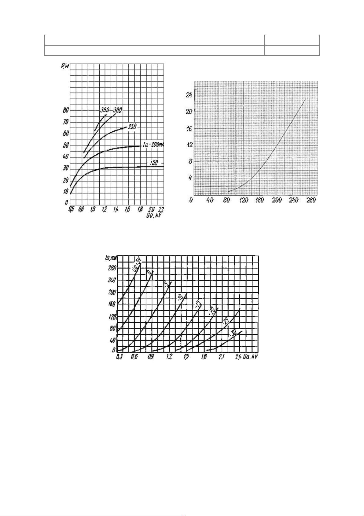
Minimum wavelength in CW operation, cm 10
Minimum wavelength in pulsed operation, cm 9
Air
m3/hr
Pa, W
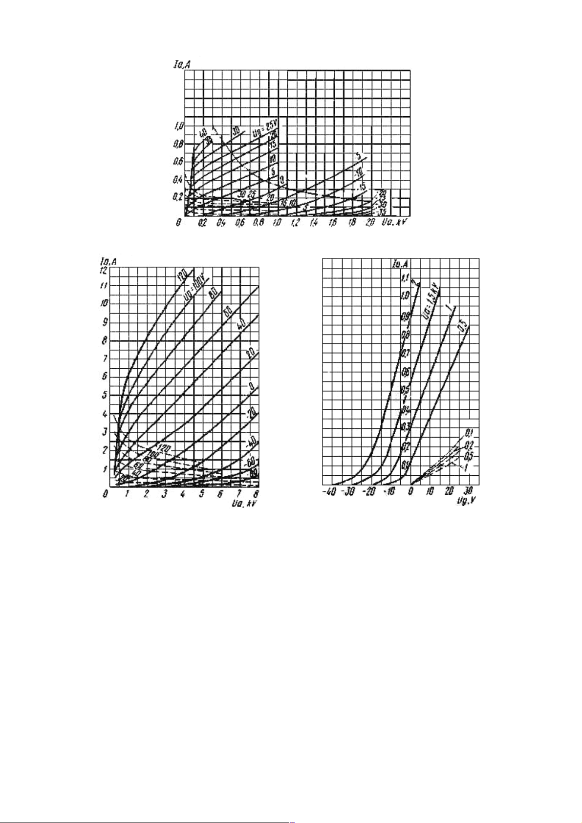
Averaged Anode Characteristic Curves:
Uf = 12.6V
Averaged Anode-Grid Characteristic Curves:
Uf = 12.6V
Page 5
ContinuousWave Generation:
L = 18.5cm
Averaged Anode Characteristic Curves:
Uf = 12.6V;
_____ anode;
_ _ _ grid-anode;
 Loading...