

Page 1
Ver 0.1 Preliminary
Jul 11, 2002
TEL: 886-3-5788833
http://www.gmt.com.tw
1
G5410
Global Mixed-mode Technology Inc.
Low noise Quasi-PWM/PFM Asynchronous Step
Down Converter
Features
+2.8V to +6V Input Range
Adjustable Output from 0.5V to VCC–1V
3A Guaranteed Output Current
95% Efficiency
Very Low Quiescent Current: 30uA(Typ.)
100% Duty Cycle for low dropout mode
600kHz +-30% Quasi PWM Operation.
Small, 6-Pin SOT23 Package
Applications
Desktop and Notebook Computers
LAN Servers
Industrial Controls
PDA
Digital Still Camera
Central Office Telecom Equipment
General Description
The G5410 is a low-noise, Quasi PWM/PFM, DC-DC
step-down converter. It powers low voltage logic and
core in small portable systems such as cellular phones,
communicating PDAs, and handy-terminals.
The device features an internal MOSFET driver to be
high efficiency buck DC/DC converter. Excellent noise
characteristics and near fixed frequency operation
provide easy post-filtering. The G5410 is ideally suited
for Li-Ion battery applications. It is also useful for +3V
or +5V fixed input applications. The device automatic
operates in two modes for higher efficiency. PWM
mode operates at a fixed frequency regardless of the
load. PFM Mode extends battery life by switching to a
pulse-skipping mode during light loads, it reducing
quiescent supply current to under 30µA.
The G5410 can deliver over 3A. The output voltage
can be adjusted from 0.5V to V
CC
-1V by external reference with the input range of +2.8V to +6V. Other
features of the G5410 include high efficiency, low
dropout mode (100% duty) at input low voltage stage.
It is available in a space-saving 6-pin SOT23-6 package
Ordering Information
Part* Temp. range Pin-package
G5410 -40°C to +85°C SOT23-6
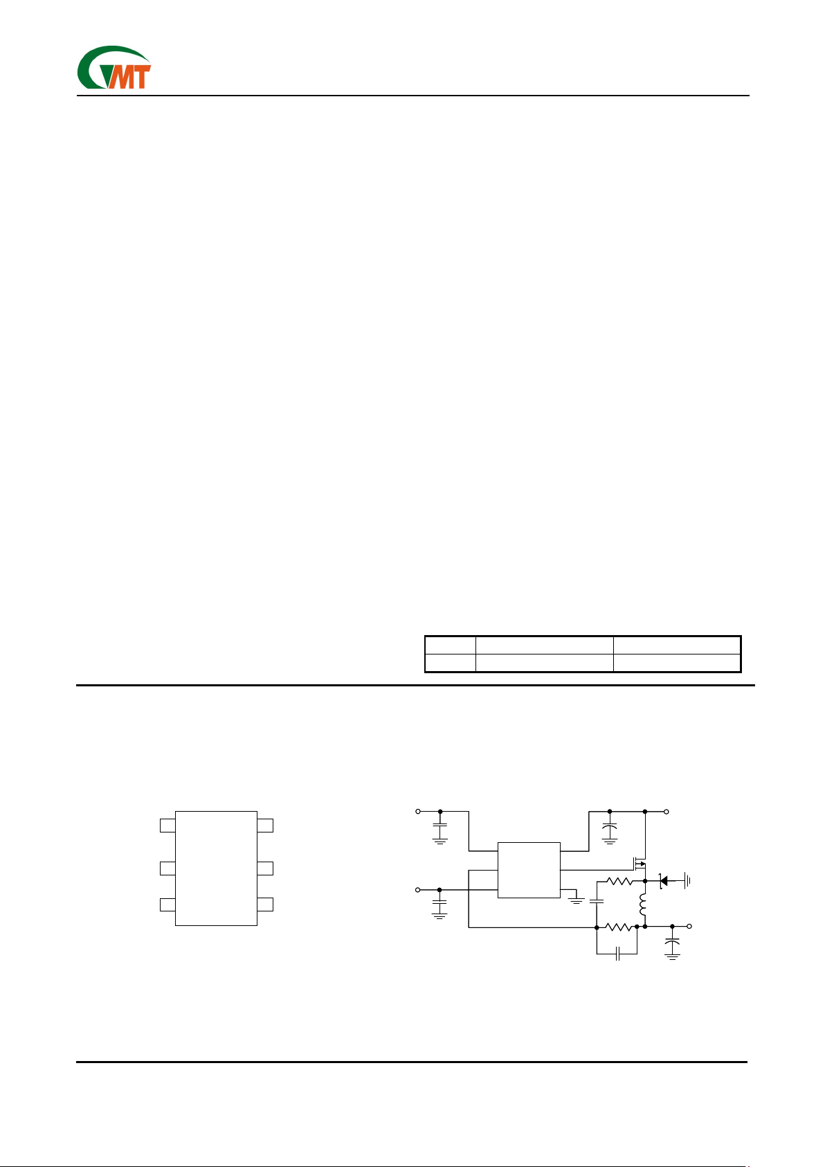
Pin Configuration Typical Operating Circuit
GND
VCC
GND
VDD
SOT 23-6
6
4
1
VREF
2
3
FB
VCC
G5410
5 DRV
VDD
DRV
FB
VREF
C1
0.1µF
C2
0.1µF
VCC
VREF
1
2
3
4
5
6
C4
100µF
G5410
R3
1M
C3
0.1µF
R2
10K
C5
470pF
C6
220µF
VOUT
VDD
Q1
Si3347
L1
5µH
D1
GND
VCC
GND
VDD
SOT 23-6
6
4
1
VREF
2
3
FB
VCC
G5410
5 DRV
GND
VDD
SOT 23-6
6
4
1
VREF
2
3
FB
VCC
G5410
5 DRV
VDD
DRV
FB
VREF
C1
0.1µF
C2
0.1µF
VCC
VREF
1
2
3
4
5
6
C4
100µF
G5410
R3
1M
C3
0.1µF
R2
10K
C5
470pF
C6
220µF
VOUT
VDD
Q1
Si3347
L1
5µH
D1
Page 2
Ver 0.1 Preliminary
Jul 11, 2002
TEL: 886-3-5788833
http://www.gmt.com.tw
2
G5410
Global Mixed-mode Technology Inc.
Absolute Maximum Ratings
VCC to GND……………..………………….…-0.3V to +7V
Output Short-Circuit Duration…………….…….….Infinite
V
DD
to GND.……………………………..……-0.3V to +7V
V
FB
to GND…………………..……………….-0.3V to +7V
V
REF
to GND….………………..……………..-0.3V to +7V
V
DRV
to GND………………………………….-0.3V to +7V
Recommend Operating Range
Supply Voltage (VCC) …………………....+2.8V to +6.0V
Driver Voltage (V
DD
). ……………..……....+2.5V to +VCC
Continuous Power Dissipation (T
A
= +25°C)
SOT23-6……………………………………...…..520 mW
SOT23-6 Thermal Resistance
θ
JA
………..240°C/Watt
Junction Temperature…………………….….……+150°C
Storage Temperature Range…………..-65°C to +160°C
Lead Temperature (soldering, 10sec)..….………+300°C
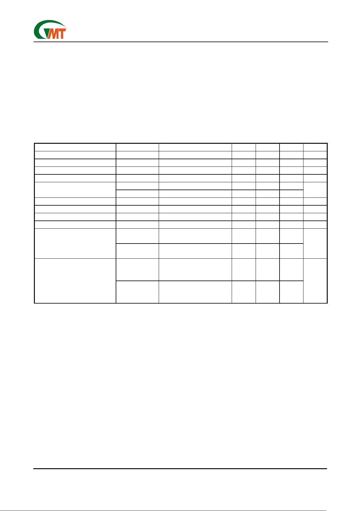
Electrical Characteristics
(V
CC
= 5V; VDD = 5V, V
REF
=1.8V, TA=25°C, unless otherwise noted.) (Note1)
PARAMETER SYMBOL CONDITION MIN TYP MAX UNITS
VCC Input Voltage Range VCC
2.8 6.0 V
VDD Driver Voltage Range VDD 2.5 VCC V
Quiescent Supply Current (ICC) ICC 30 µA
Quiescent Supply Current (IDD) IDD 0.2 µA
I
REF
V
REF
=1.8V 0.3
Input Pin Bias Current
I
FB
V
FB
=1.8V 0.3
nA
Input Offset Voltage V
IOS
V
REF
=1.8V -10 10 mV
V
REF
Operating Range V
REF
-0.3 VCC-1.6 V
Driver Pin High Level VOH IOH=10mA VDD-0.1 V
Driver Pin Low Level VOL I
OL
=10mA 0.01 V
R
ONH
Source
I
Source
=10mA
7.9
Driver Resistance
R
ONL
Sink
I
Sink
=10mA
6.1
Ω
t
PGDH
V
REF
=1.8V
V
FB=VREF
+50Mv
C
DRV
=2200pF
1.2
Propagation Delay
t
PGDL
V
FB
=1.8V
V
REF
=VRB+50mV
C
DRV
=2200pF
0.6
µS
Note 1: Limits is 100% production tested at TA= +25°C. Low duty pulse techniques are used during test to main-
tain junction temperature as close to ambient as possible.
Page 3

Ver 0.1 Preliminary
Jul 11, 2002
TEL: 886-3-5788833
http://www.gmt.com.tw
3
G5410
Global Mixed-mode Technology Inc.
Overview
The G5410 is buck (step-down) DC-DC controller that
uses a Q-PWM control scheme. The control scheme is
designed to quick response to output loading change
at the FB pin, the gate drive (DRV pin) turns the external PFET on or off. When the inductor current is too
high, the current limit protection circuit engages and
turns the PFET off for approximately 9µs. The Q-PWM
control does not provide an internal oscillator. Switching frequency depends on the external components
and operating conditions. Operating frequency reduces at light loads resulting in excellent efficiency
compared to other architectures. Two external resistors can easily program the output voltage. The output
can be set in a wide range from 0.5V to V
IN
.
Quasi-PWM/PFM Control Circuit
The G5410 operates in discontinuous conduction
mode at light load current or continuous conduction
mode at heavy load current. In discontinuous conduction mode, current through the inductor starts at zero
and ramps up to the peak, then ramps down to zero.
Next cycle starts when the FB voltage reaches the
internal voltage. Until then, the inductor current remains zero. Operating frequency is lower and switching losses reduce. In continuous conduction mode,
current always flows through the inductor and never
ramps down to zero. The output voltage (V
OUT
) can be
programmed by 2 external resistors. It can be calculated as following.
V
OUT
= Vref x (R1 +R2)/R2
Functional Description
For example, with V
OUT
set to 3.3V, V
OUT_PP
is 26.6mV
V
RIPPLE
= 0.01 x (33K + 20K) / 20K = 0.0266V
Operating frequency is determined by knowing the
input voltage, output voltage, inductor, VHYST, ESR
(Equivalent Series Resistance) of output capacitor,
and the delay. It can be approximately calculated using the formula:
V
OUT
(VIN-V
OUT
) x ESR
F =
V
IN
X
V
HYST
xαx L)+(V
IN
x delay x ESR)
α
: (R1+R2) / R2
delay: It includes the G5410 propagation delay time
and the PFET delay time.
The operating frequency and output ripple voltage can
also be significantly influenced by the speed up capacitor (Cff). Cff is connected in parallel with the high
side feedback resistor, R1. The location of this capacitor is similar to where a feed forward capacitor
would be located in a PWM control scheme. However
it’s effect on hysteretic operation is much different. The
output ripple causes a current to be sourced or sunk
through this capacitor. This current is essentially a
square wave. Since the input to the feedback pin, FB,
is a high impedance node, the current flows through
R2. The end result is a reduction in output ripple and
an increase in operating frequency. When adding Cff,
calculate the formula above withα = 1. The value of
Cff depend on the desired operating frequency and the
value of R2. A good starting point is 470pF ceramic at
100kHz decreasing linearly with increased operating
frequency. Also note that as the output voltage is programmed below 2.5V, the effect of Cff will decrease
significantly.
Design Information
Hysteretic control is a simple control scheme. However the operating frequency and other performance
characteristics highly depend on external conditions
and components. If either the inductance, output
capacitance, ESR, V
IN
, or Cff is changed, there will be
a change in the operating frequency and output ripple.
The best approach is to determine what operating
frequency is desirable in the application and then begin with the selection of the inductor and C
OUT
ESR.
Page 4

Ver 0.1 Preliminary
Jul 11, 2002
TEL: 886-3-5788833
http://www.gmt.com.tw
4
G5410
Global Mixed-mode Technology Inc.
Inductor Selection (L1)
The important parameters for the inductor are the inductance and the current rating. The G5410 operates
over a wide frequency range and can use a wide
range of inductance values. A good rule of thumb is to
use the equations used for National’s
Simple Switch-
ers
®
The equation for inductor ripple as a function of output
current is:
for i
out
< 2.0Amps
Di
≤
i
out
x 0.386827 x i
out -.366726
for i
out
> 2.0Amps
Di ≤ i
out
• 0.3
The inductance can be calculated based upon the desired operating frequency where:
V
IN
- V
DS
- V
OUT
D
L =
△
i
x
f
and
V
OUT
+ VD
D =
V
IN
- V
DS
- VD
where V
D
is diode forward voltage.
The inductor should be rated to the following:
I
pk
= (I
out
+Di/2)*1.1
I
RMS
=
3
i
Iout
2
2
∆
+
The inductance value and the resulting ripple is one of
the key parameters controlling operating frequency.
The second is the ESR.
Output Capacitor Selection (C
OUT
)
The ESR of the output capacitor times the inductor
ripple current is equal to the output ripple of the regulator. However, the V
HYST
sets the first order value of
this ripple. As ESR is increased with a given inductance, then operating frequency increases as well. If
ESR is reduced then the operating frequency reduces.
The use of ceramic capacitors has become a common
de-sire of many power supply designers. However,
ceramic capacitors have a very low ESR resulting in a
90° phase shift of the output voltage ripple. This results in low operating frequency and increased output
ripple. To fix this problem a low value resistor should
be added in series with the ceramic output capacitor.
Although counter intuitive, this combination of a ceramic capacitor and external series resistance provide
highly accurate control over the output voltage ripple.
The other types capacitor, such as Sanyo POS CAP
and OS-CON, Panasonic SP CAP, Nichicon ’NA’ series, are also recommended and may be used without
additional series resistance.
For all practical purposes, any type of output capacitor
may be used with proper circuit verification.
Input Capacitor Selection (C
IN
)
A bypass capacitor is required between the input
source and ground. It must be located near the source
pin of the external PFET. The input capacitor prevents
large voltage transients at the input and provides the
instantaneous current when the PFET turns on. The
important parameters for the input capacitor are the
voltage rating and the RMS current rating. Follow the
manu-facturer’s recommended voltage derating. For
high input voltage application, low ESR electrolytic
capacitor, the Nichicon ’UD’ series or the Panasonic ’FK’ series, is available. The RMS current in the
input capacitor can be calculated.
V
OUT
x (VIN-V
OUT
))
1/2
I
RMS_CIN
=I
OUT
x
V
IN
The input capacitor power dissipation can be calculated as follows.
P
D(CIN) =IRMS_CIN2
x ES
RCIN
The input capacitor must be able to handle the RMS
current and the P
D
. Several input capacitors may be
connected in parallel to handle large RMS currents. In
some cases it may be much cheaper to use multiple
electrolytic capacitors than a single low ESR, high
performance capacitor such as OS-CON or Tantalum.
The capacitance value should be selected such that
the ripple voltage created by the charge and discharge
of the capacitance is less than 10% of the total ripple
across the capacitor.
Catch Diode Selection
The important parameters for the catch diode are the
peak current, the peak reverse voltage, and the average power dissipation. The average current through
the diode can be calculated as following.
I
D_AVE
= I
OUT
x (1 - D)
The off state voltage across the catch diode is approximately equal to the input voltage. The peak reverse voltage rating must be greater than input voltage.
In nearly all cases a shottky diode is recommended. In
low output voltage applications a low forward voltage
provides improved efficiency. For high temperature
applications, diode leakage current may become significant and require a higher reverse voltage rating to
achieve acceptable performance.
Page 5

Ver 0.1 Preliminary
Jul 11, 2002
TEL: 886-3-5788833
http://www.gmt.com.tw
5
G5410
Global Mixed-mode Technology Inc.
P-Channel MOSFET Selection (Q1)
The important parameters for the PFET are the maximum Drain-Source voltage (V
DS
), the on resistance
(R
DSON
), Current rating, and the input capacitance. The
voltage across the PFET when it is turned off is equal
to the sum of the input voltage and the diode forward
voltage. The V
DS
must be selected to provide some
margin beyond the input voltage. DRV swings the
PFET’s gate from V
IN
to VIN - 5V when the input voltage is greater than 7V. At less than 7V input, the DRV
voltage swing is smaller. At 4.5V input the DRV swings
from V
IN
to VIN - 3.3V. To insure that the PFET turns
on completely, a low threshold PFET should be used
when the input voltage is less than 7V. RDSON and
package size must be used to determine the appropriate FET for a given current as well as peak current
capability. Switching losses also must be considered.
The first order losses in the FET are approximately:
PDswitch = R
DSON
x I
OUT
2 x D +f x I
OUT
x VIN x (ton + toff) / 2
Where:
t
on
= FET turn on time
t
off
= FET turn off time
A value of 10ns to 20ns is typical for ton and t
off
. The
R
DSON
is used in determining the current limit resistor
value, R
ADJ
. Note that the R
DSON
has a positive temperature coefficient. At 100°C, the RDSON may be as
much as 150% higher than the 25°C value. This increase in RDSON must be considered it when determining RADJ in wide temperature range applications.
If the current limit is set based upon 25°C ratings, then
false current limiting can occur at high temperature.
Keeping the gate capacitance below 2000pF is recommended to keep switching losses and transition
times low. As gate capacitance increases, operating
frequency should be reduced and as gate capacitance
decreases operating frequency can be increased.
PCB Layout
The PC board layout is very important in all switching
regulator designs. Poor layout can cause switching
noise into the feedback signal and general EMI problems. For minimal inductance, the wires indicated by
heavy lines should be as wide and short as possible.
Keep the ground pin of the input capacitor as close as
possible to the anode of the diode. This path carries a
large AC current. The switching node, the node with
the diode cathode, inductor, and FET drain, should be
kept short. This node is one of the main sources for
radiated EMI since it is an AC voltage at the switching
frequency. It is always good practice to use a ground
plane in the design, particularly at high currents. The
gate pin of the external PFET should be located close
to the DRV pin.
However, if a very small FET is used, a resistor may
be required between DRV and the gate of the FET to
reduce high frequency ringing. The feedback voltage
signal line can be sensitive to noise. Make sure to
avoid inductive coupling to the inductor or the switching node.
Block Diagram
Comp
+
-
Duty
Comp
VCC
Vfb
Ref in
VDD
Drv
GND
Driver
Comp
+
-
Duty
Comp
VCC
Vfb
Ref in
VDD
Drv
GND
Driver
Page 6

Ver 0.1 Preliminary
Jul 11, 2002
TEL: 886-3-5788833
http://www.gmt.com.tw
6
G5410
Global Mixed-mode Technology Inc.
Typical Performance Characteristics
(VCC= +5.0V, VDD=+5.0V, C1=C2=0.1µF, C4=100µF, C6=150µF, V
REF
=1.8V, TA=25°C, unless otherwise noted.)
0
5
10
15
20
25
30
35
40
45
50
1.0 1.5 2.0 2.5 3.0 3.5 4.0 4.5 5.0 5.5 6.0
Input Supply Voltage Vcc (V)
Quiescent Supply Current Icc (µA)
Icc @ Vdd=3V
Icc @ Vdd=4V
Icc @ Vdd=5V
V
REF=VCC
-2.6V
V
FB=VREF
- 50mV
-5
-4
-3
-2
-1
0
1
2
3
4
5
4.5 4.6 4. 7 4.8 4.9 5. 0 5.1 5.2 5. 3 5.4 5.5 5.6 5.7 5. 8 5.9 6.0
Vcc Supply Voltage (V)
Input Bias Current (IFB) (nA)
IREF @ Vdd=2.6V
IREF @ V dd=3V
IREF @ V dd=4V
IREF @ V dd=5V
-5
-4
-3
-2
-1
0
1
2
3
4
5
4.5 4.6 4.7 4.8 4.9 5.0 5.1 5.2 5.3 5.4 5.5 5.6 5.7 5.8 5.9 6.0
Vcc Input Supply Voltage (V)
Input Bias Current (IREF) (nA)
IFB @ Vdd=2.6V
IFB @ Vdd=3V
IFB @ Vdd=4V
IFB @ Vdd=5V
-10
-8
-6
-4
-2
0
2
4
6
8
10
4.2 4.4 4.6 4.8 5.0 5.2 5.4 5.6 5.8 6.0
Vcc Input Supply Voltage (V)
Input Offset Voltage (mV)
VIOS @ Vdd=3V
VIOS @ Vdd=4V
VIOS @ Vdd=5V
V
REF
= 1.8V
-10
-8
-6
-4
-2
0
2
4
6
8
10
2.5 3.0 3.5 4.0 4.5 5.0 5.5
Driver Input Voltage (V)
Input Offset Voltage (mV)
VIOS @ Vcc=4.2V
VIOS @ Vcc=4.4V
VIOS @ Vcc=5.0V
VIOS @ Vcc=5.4V
-1.0
-0.8
-0.6
-0.4
-0.2
0.0
0.2
0.4
0.6
0.8
1.0
1.0 1.5 2.0 2.5 3.0 3.5 4.0 4.5 5.0 5.5 6.0
Vdd (Voltage)
Quiescent Supply Current IDD (µA)
IDDL(uA) Vcc=4V
IDDL(uA) Vcc=5V
IDDL(uA) Vcc=5.6V
IDDL(uA) Vcc=6V
V
REF=VCC
-2.6V
V
FB=VREF
- 50mV
V
REF
= 1.8V
VFB = 1.8V
V
REF
= 1.8V
Quiescent Supply Current (ICC) vs. V
CC
Quiescent Supply Current (IDD) vs. V
DD
Input Bias Current (IFB) vs. V
CC
Input Bias Current (IREF) vs. V
CC
Input Offset Voltage vs. V
CC
Input Offset Voltage vs. V
DD
Page 7

Ver 0.1 Preliminary
Jul 11, 2002
TEL: 886-3-5788833
http://www.gmt.com.tw
7
G5410
Global Mixed-mode Technology Inc.
Typical Performance Characteristics
(Continued)
0
1
2
3
4
5
6
7
8
9
10
11.522.533.544.555.56
Vcc Input Voltage (V)
Driver High Level V
OH
(V)
VOH @ Vdd=2.6V
VOH @ Vdd=3.0V
VOH @ Vdd=4.0V
VOH @ Vdd=5.0V
0
1
2
3
4
5
6
7
1.0 1.5 2.0 2.5 3.0 3.5 4.0 4.5 5.0 5.5
Driver Input Voltage VDD (V)
Driver Output High Lever (V)
VOH @ Vcc= 3.0V
VOH @ Vcc= 4.0V
VOH @ Vcc= 4.2V
VOH @ Vcc= 5.0V
VOH @ Vcc= 5.6V
0.0
0.1
0.2
0.3
0.4
0.5
0.6
0.7
0.8
0.9
1.0
2.5 3.0 3.5 4.0 4. 5 5.0 5.5
Driver Input Voltage VDD (V)
Driver Ouput Low Level (V)
VOL @ Vcc=4.0V
VOL @ Vcc=4.2V
VOL @ Vcc=5.0V
VOL @ Vcc=5.6V
V
REF=VCC
-2.6V
V
FB=VREF
+ 50mV
V
REF=VCC
-2.6V
V
FB=VREF
- 50mV
-0.10
-0.05
0.00
0.05
0.10
2.5 3.0 3.5 4.0 4.5 5.0 5. 5 6.0
Vcc (Voltage)
Output Driver Low Level VOL (V)
V
REF=VCC
-2.6V
V
FB=VREF
- 50mV
V
REF=VCC
-2.6V
V
FB=VREF
- 50mV
V
REF=VCC
-2.6V
V
FB=VREF
+ 50mV
5
10
15
20
25
30
35
40
45
50
1.5 2.0 2.5 3.0 3.5 4.0 4.5 5.0
Driver Input Voltage (V)
Driver On-Resistance (High-state) (
Ω
)
RONH @ VCC=3.0V
RONH @ VCC=4.0V
RONH @ VCC=4.5V
RONH @ VCC=5.0V
V
REF
=1.8V
4
6
8
10
12
14
16
18
20
22
24
26
1.5 2.0 2.5 3.0 3.5 4.0 4.5 5.0
Driver Input Voltage (V)
Driver On-Resistance (Low-state) (
Ω
)
RONL @ VCC=3.0V
RONL @ VCC=4.0V
RONL @ VCC=4.5V
RONL @ VCC=5.0V
V
REF
=1.8V
Driver High Level vs. Vcc
Driver Low Level vs. Vcc
Driver High Level vs. V
DD
Driver Low Level vs. V
DD
Driver On-Resistance (High-state) vs. V
DD
Driver On-Res istance (Low -state) vs. V
DD
Page 8

Ver 0.1 Preliminary
Jul 11, 2002
TEL: 886-3-5788833
http://www.gmt.com.tw
8
G5410
Global Mixed-mode Technology Inc.
Typical Performance Characteristics
(Continued)
0
5
10
15
20
25
30
35
40
45
50
-40-35-30-25-20-15-10-5 0 5 10 15 20 25 30 35 40 45 50 55 60 65 70 75 80 85
Ambient Temperatu TA (°C)
Quiescent Current (ICC) (µA)
ICC @ Vcc=3V
ICC @ Vcc=4V
ICC @ Vcc=5V
VCC=5V,VDD=5V
V
REF
=1.8V
V
FB=VREF-
50mV
-1.00
-0.75
-0.50
-0.25
0.00
0.25
0.50
0.75
1.00
-40-35-30-25-20-15-10-5 0 5 10 15 20 25 30 35 40 45 50 55 60 65 70 75 80 85
Ambient Temperature TA (°C)
Quiescent Current (IDD) (µA)
IDDH @ Vdd=2.5V
IDDH @ Vdd=3.0V
IDDH @ Vdd=3.5V
IDDH @ Vdd=4.0V
IDDH @ Vdd=4.5V
IDDH @ Vdd=5.0V
-20
-15
-10
-5
0
5
10
15
20
-40-35-30-25-20-15-10-5 0 5 10 15 20 25 30 35 40 45 50 55 60 65 70 75 80 85
Ambient Temperature (°C)
Input Bias Current IREF (nA)
IBIASN@Vref=0.2V
IBIASN@Vref=0.6V
IBIASN@Vref=1.0V
IBIASN@Vref=1.4V
IBIASN@Vref=1.8V
IBIASN@Vref=2.0V
IBIASN@Vref=2.4V
-15
-13
-11
-9
-7
-5
-3
-1
1
3
5
7
9
11
13
15
-40-35-30-25-20-15-10-5 0 5 10 15 20 25 30 35 40 45 50 55 60 65 70 75 80 85
Ambient Temperature (°C)
Input Bias Current IFB (nA)
IBIASP@Vref=0.2V
IBIASP@Vref=0.6V
IBIASP@Vref=1.0V
IBIASP@Vref=1.4V
IBIASP@Vref=1.8V
IBIASP@Vref=2.0V
IBIASP@Vref=2.4V
0
5
10
15
20
25
30
-40-35-30-25-20-15-10-5 0 5 10 15 20 25 30 35 40 45 50 55 60 65 70 75 80 85
Ambient Temperature (°C)
Driver On-Resistance (High state) (
Ω
)
RONH @ Vdd=2.5V
RONH @ Vdd=3.0V
RONH @ Vdd=3.5V
RONH @ Vdd=4.0V
RONH @ Vdd=4.5V
RONH @ Vdd=5.0V
0
2
4
6
8
10
12
14
16
18
20
-40-35-30-25-20-15-10-5 0 5 10 15 20 25 30 35 40 45 50 55 60 65 70 75 80 85
Ambient Temperature (°C)
Driver On-Resistance (Low-state) (
Ω
)
RONL @ Vdd= 2.5V
RONL @ Vdd= 3.0V
RONL @ Vdd= 3.5V
RONL @ Vdd= 4.0V
RONL @ Vdd= 4.5V
RONL @ Vdd= 5.0V
VCC=5V,VDD=5V
V
REF
=1.8V
V
FB=VREF-
50mV
VCC=5V, VDD=5VVCC=5V, VDD=5V
Quiescent Current (ICC) vs. Tempreature Quiescent Current (IDD) vs. Tempreature
Input Bias Current (IREF) vs. Temperature Input Bias Current (IFB) vs. Temperature
Driver On-Resistance
(Hig
h-state) vs. Temperature
Driver On-Resistance (Low-state) vs. Temperature
Page 9

Ver 0.1 Preliminary
Jul 11, 2002
TEL: 886-3-5788833
http://www.gmt.com.tw
9
G5410
Global Mixed-mode Technology Inc.
Typical Performance Characteristics
(Continued)
-10
-8
-6
-4
-2
0
2
4
6
8
10
-40-35-30-25-20-15-10-5 0 5 10 15 20 25 30 35 40 45 50 55 60 65 70 75 80 85
Ambient Temperature (°C)
Offset Voltage Vios(mV)
VCC=5V
V
DD
=5V
V
REF
=1.8V
Input Offset Voltage vs. Temperature Propogation Delay
Propogation Delay
Discontinuous Mode Operation
( VDD 5V, V
OUT
1.8V, 100mA Load, 150µF tan C
OUT
)
Continuous Mode Operation
( VDD 5V, V
OUT
1.8V, 500mA Load, 150µF tan C
OUT
)
Continuous Mode Operation
( VDD 5V, V
OUT
1.8V, 2A Load, 150µF tan C
OUT
)
Page 10

Ver 0.1 Preliminary
Jul 11, 2002
TEL: 886-3-5788833
http://www.gmt.com.tw
10
G5410
Global Mixed-mode Technology Inc.
Typical Performance Characteristics
(Continued)
Power Up Waf eworm
Power Off Waveform
Load Transient Response (0.1A
←→
←→←→
←→
2A)
V
CC
Line Transient Response (I
LOAD
=100mA)
V
CC
Line Transient Response (I
LOAD
=500mA)
Load Transient Response (0.1A
←→
←→←→
←→
0.9A)
Page 11

Ver 0.1 Preliminary
Jul 11, 2002
TEL: 886-3-5788833
http://www.gmt.com.tw
11
G5410
Global Mixed-mode Technology Inc.
Typical Performance Characteristics
(Continued)
30
40
50
60
70
80
90
100
0 200 400 600 800 1000 1200 1400 1600 1800 2000 2200
Load Current (mA)
Effieiency (%)
Vdd=3.0V
Vdd=3.3V
Vdd=4.0V
Vdd=5.0V
30
40
50
60
70
80
90
100
0 200 400 600 800 1000 1200 1400 1600 1800 2000 2200
Load Current (mA)
Effieiency (%)
Vdd=2.5V
Vdd=3.3V
Vdd=4.5V
Vdd=5.0V
Vdd=5.5V
30
40
50
60
70
80
90
100
0 200 400 600 800 1000 1200 1400 1600 1800 2000 2200
Load Current
(mA)
Efficiency (%)
Vdd=2.5V
Vdd=3.3V
Vdd=4.0V
Vdd=4.5V
Vdd=5.0V
Vdd=5.5V
30
40
50
60
70
80
90
0 200 400 600 800 1000 1200 1400 1600 1800 2000 2200
Load Current (mA)
Effieiency (%)
Vdd=2.5V
Vdd=3.0V
Vdd=3.3V
Vdd=5.0V
VDD Line Transient Response (I
LOAD
=100mA)
V
DD
Line Transient Response (I
LOAD
=500mA)
Efficiency vs. Load Current (V
OUT
=2.5V) Efficiency vs. Load Current (V
OUT
=1.8V)
Efficiency vs. Load Current (V
OUT
=1.5V)
Efficiency vs. Load Current (V
OUT
=1.25V)
Page 12

Ver 0.1 Preliminary
Jul 11, 2002
TEL: 886-3-5788833
http://www.gmt.com.tw
12
G5410
Global Mixed-mode Technology Inc.
Package Information
Note:
1. Package body sizes exclude mold flash protrusions or gate burrs
2. Tolerance ±0.1000 mm (4mil) unless otherwise specified
3. Coplanarity: 0.1000mm
4.
Dimension L is measured in gage plane
DIMENSIONS IN MILLIMETERS
SYMBOLS
MIN
NOM MAX
A 1.00 1.10 1.30
A1 0.00 ----- 0.10
A2 0.70 0.80 0.90
b 0.35 0.40 0.50
C 0.10 0.15 0.25
D 2.70 2.90 3.10
E 1.40 1.60 1.80
e ----- 1.90(TYP) -----
H 2.60 2.80 3.00
L 0.37 ------ -----
θ
1
1º 5º 9º
Taping Specification
E
e
D
H
θ
1
L
C
b
A2
A1
A
e1
E
e
D
H
θ
1
L
C
b
A2
A1
A
e1
Feed Directio n
SOT 23-6 Package Orientation
Feed Directio n
SOT 23-6 Package Orientation
 Loading...