

Page 1
Global Mixed-mode Technology Inc.
Dual-Slot PCMCIA/CardBus Power Controllers
DS(on)
(180-m
TM
Interface
5V VCC Switch and 3.3V VCC
ΩΩΩΩ
Description
The G576 PC Card power-interface switch provides an
integrated power-management solution for dual-slot
PC Cards. All of the discrete power MOSFETs, a logic
section, current limiting, and thermal protection for PC
Card control are combined on a single integrated circuit. The circuit allows the distribution of 3.3V, 5V,
and/or 12V card power, and is compatible with many
PCMCIA controllers. The current-limiting feature
eliminates the need for fuses, which reduces component count and improves reliability. Current-limit reporting can help the user isolate a system fault to the
PC Card.
The G576 features a 3.3V low voltage mode that allows for 3.3V switching without the need for 5V. Bias
power can be derived from either the 3.3V or 5V inputs.
This facilitates low-power system designs such as
sleep mode and pager mode where only 3.3V is
available.
Features
Fully Integrated VCC and VPP Switching for
Dual-Slot PC Card
Low r
Switch)
3.3V Low-Voltage Mode
Meets PC Card Standards
12V Supply Can Be Disabled Except During
12V Flash Programming
Short Circuit and Thermal Protection
28 Pin SSOP
Compatible With 3.3V, 5V, and 12V PC Cards
Break-Before-Make Switching
Application
Notebook PC
Electronic Dictionary
Personal Digital Assistance
Digital still Camera
G576
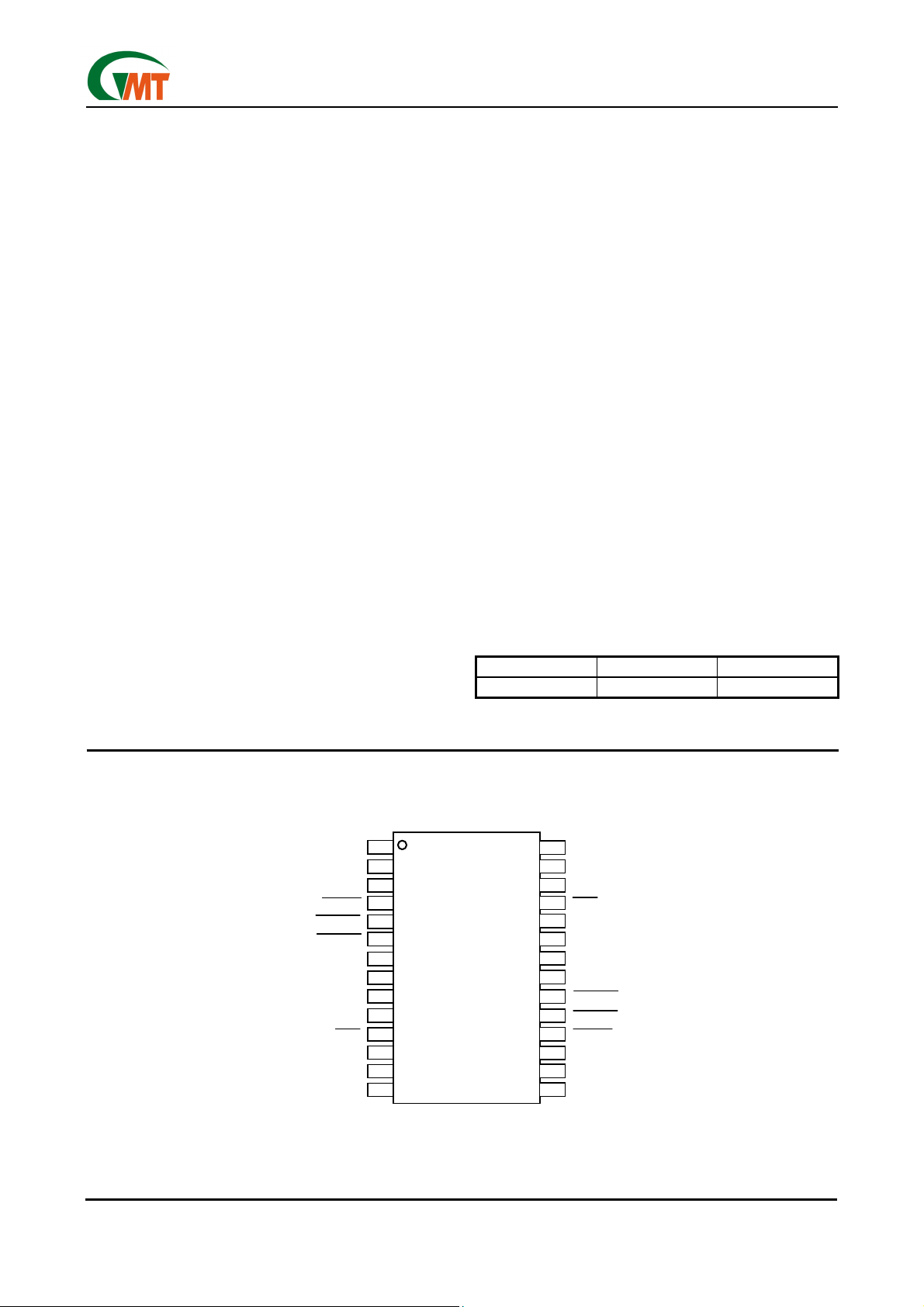
Pin Configuration
AVCC
AVCC
AVPPD1
AVPPD1
AVPPD0
AVPPD0
ASHDN
ASHDN
AVCCD0
AVCCD0
AVCCD1
AVCCD1
VCC3
VCC3
VCC5
VCC5
VCC5
VCC5
GND
GND
BOC
BOC
VCC12
VCC12
BVPP
BVPP
BVCC
BVCC
10
10
11
11
12
12
13
13
14
14
End equipment for the G576 includes notebook computers, desktop computers, personal digital assistants
(PDAs), digital cameras and bar-code scanners.
Ordering Information
PART NUMBER TEMP. RANGE PACKAGE
G576 -40°C to +85°C 28-SSOP
G576
G576
1
1
2
2
3
3
4
4
5
5
6
6
7
7
8
8
9
9
28
28
27
27
26
26
25
25
24
24
23
23
22
22
21
21
20
20
19
19
18
18
17
17
16
16
15
15
AVCC
AVCC
AVPP
AVPP
VCC12
VCC12
AOC
AOC
GND
GND
VCC5
VCC5
VCC5
VCC5
VCC3
VCC3
BVCCD1
BVCCD1
BVCCD0
BVCCD0
BSHDN
BSHDN
BVPPD0
BVPPD0
BVPPD1
BVPPD1
BVCC
BVCC
Ver: 1.0
Jan 23, 2003
28Pin SSOP
28Pin SSOP
1
TEL: 886-3-5788833
http://www.gmt.com.tw
Page 2
Global Mixed-mode Technology Inc.
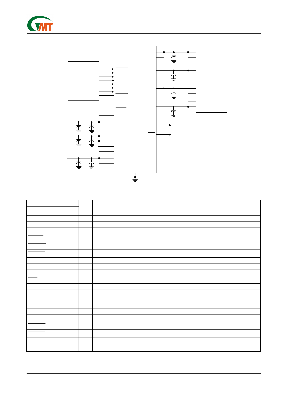
Typical PC-card Power-distribution application
AVCC
AVCC
AVCC
AVCC
AVCCD0
12V
12V
5V
5V
3.3V
3.3V
Controller
Controller
0.1µF
0.1µF
0.1µF
0.1µF
0.1µF
0.1µF
PCMCIA
PCMCIA
From CPU
From CPU
From CPU
From CPU
1µF
1µF
1µF
1µF
1µF
1µF
AVCCD0
AVCCD1
AVCCD1
AVPPD0
AVPPD0
AVPPD1
AVPPD1
BVCCD0
BVCCD0
BVCCD1
BVCCD1
BVPPD0
BVPPD0
BVPPD1
BVPPD1
ASHDN
ASHDN
BSHDN
BSHDN
VCC12
VCC12
VCC12
VCC12
VCC5
VCC5
VCC5
VCC5
VCC5
VCC5
VCC5
VCC5
VCC3
VCC3
VCC3
VCC3
G576
G576
GND
GND
GND
GND
AVPP
AVPP
BVCC
BVCC
BVCC
BVCC
BVPP
BVPP
AOC
AOC
BOC
BOC
0.1µF
0.1µF
0.1µF
0.1µF
0.1µF
0.1µF
0.1µF
0.1µF
To CPU
To CPU
To CPU
To CPU
V
V
CC1
CC1
V
V
CC2
CC2
V
V
PP1
PP1
V
V
PP2
PP2
V
V
CC1
CC1
V
V
CC2
CC2
V
V
PP1
PP1
V
V
PP2
PP2
PC Card
PC Card
Connector
Connector
A
A
PC Card
PC Card
Connector
Connector
B
B
G576
Terminal Functions
TERMINAL
NAME NO.
AVCC 1,28 O Switched output that delivers 0V, 3.3V, 5V, or high impedance to card
AVPPD1 2 I Logic input that controls voltage of AVPP (see control-logic table)
AVPPD0 3 I Logic input that controls voltage of AVPP (see control-logic table)
ASHDN
0AVCCD
1AVCCD
VCC3 7,21 I 3.3V VCC input for card power and/or chip power if 5V is not present
VCC5 8,9,22,23 I 5V VCC input for card power and/or chip power
GND 10,24 Ground
BOC
VCC12 12,26 I 12V VPP input card power
BVPP 13 O Switched output that delivers 0V, 3.3V, 5V, 12V or high impedance to card
BVCC 14,15 O Switched output that delivers 0V, 3.3V, 5V, or high impedance to card
BVPPD1 16 I Logic input that controls voltage of BVPP (see control-logic table)
BVPPD0 17 I Logic input that controls voltage of BVPP (see control-logic table)
BSHDN
AOC
0BVCCD
1BVCCD
AVPP 27 O Switched output that delivers 0V, 3.3V, 5V, 12V or high impedance to card
4 I Logic input that shuts down AVPP/AVCC and sets AVPP/AVCC to high-impedance state
5 I Logic input that controls voltage of AVCC (see control-logic table)
6 I
11 O Logic-level overcurrent reporting output that goes low when an overcurrent condition exists
18 I Logic input that shuts down BVPP/BVCC and set BVPP/BVCC to high-impedance state
19
20
25 O Logic-level overcurrent reporting output that goes low when an overcurrent condition exists
I/O DESCRIPTION
Logic input that controls voltage of AVCC (see control-logic table)
I Logic input that controls voltage of BVCC (see control-logic table)
I
Logic input that controls voltage of BVCC (see control-logic table)
Ver: 1.0
Jan 23, 2003
2
TEL: 886-3-5788833
http://www.gmt.com.tw
Page 3
Global Mixed-mode Technology Inc.
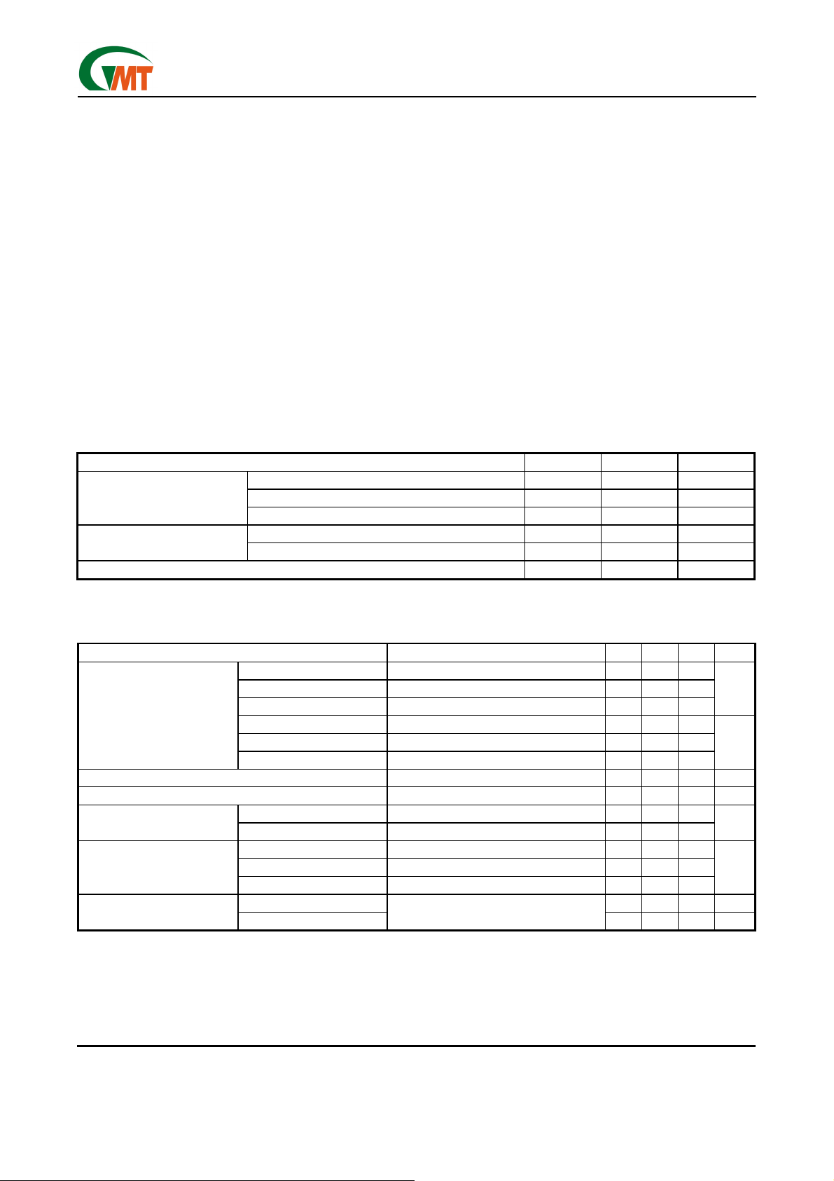
Absolute Maximum Ratings Over Operating
Free-Air Temperature
Input voltage range for card power:
VCC5.......................................………..…….-0.3V to 7V
VCC3.....…...........................…….……... -0.3V to 7V
VCC12.....................................……..…….-0.3V to 14V
Logic input voltage...................….........…….-0.3V to 7V
Output current (each card):I
I
Operating virtual junction temperature range, T
.........…............……………..…….………-40°C to 150°C
*
Stresses beyond those listed under "absolute maximum ratings”may cause permanent damage to the device. These are stress rating
only, and functional operation of the device at these or any other conditions beyond those indicated under "recommended operating
conditions”is not implied. Exposure to absolute–maximum-rated conditions for extended periods may affect device reliability.
Note 1: ESD (electrostatic discharge) sensitive device. Proper ESD precautions are recommended to avoid performance degradation or
less of functionality.
(unless other-wise noted)*
O (AVCC/BVCC)..
O(AVPP/BVPP)..…
internally limited
internally limited
J.
Operating free-air temperature range,.T
……………………………………………………………..……………..
Storage temperature range, T
STG
………………………...........….....……….-55°C to 150°C
Lead temperature 1.6 mm (1/16 inch) from case for
10 seconds.……..………………………………...….260°C
Thermal resistance
θ
JA
SSOP 28……………………………………….….125°C/W
Power dissipation P
D
(T
+25°C)
≤
A
SSOP 28……………………………………………800mW
ESD…………………………..…………………….…Note1
G576
A
-40°C to 85°C
Recommended Operating Conditions
VCC5 0 5.25 V
Input voltage, VI
Output current
Operating virtual junction temperature, TJ -40 125
VCC3 0 5.25 V
VCC12 0 13.5 V
I
O (AVCC/BVCC)
I
O (AVPP/BVPP)
1.0 A
150 mA
MIN MAX UNIT
°C
(TA=25°C)
Electrical Characteristics
Power Switch
PARAMETER TEST CONDITIONS* MIN TYP MAX UNIT
5V to AVCC/BVCC VCC5 = 5V 130 180
3.3V to AVCC/BVCC VCC5 = 5V, VCC3 =3.3V 130 180
Switch resistance
V
O (AVPP/BVPP)
V
O (AVCC/BVCC)
I
IKG
I
I
OS
current Limit
*Pulse-testing techniques maintain junction temperature close to ambient temperatures; thermal effects must be taken into account separately.
Clamp low voltage IPP at 10mA 0.18 0.8 V
Clamp low voltage ICC at 10mA 0.13 0.8 V
Leakage current
Input current
Short-circuit Output-
3.3V to AVCC/BVCC VCC5 = 0V, VCC3 =3.3V 130 180
5V to AVPP/BVPP TJ = 25°C 3.6 6
3.3V to AVPP/BVPP TJ = 25°C 3.4 6
12V to AVPP/BVPP T
IPP high-impedance State TA = 25°C 1 10
I
high-impedance State TA = 25°C 1 10
CC
VCC5 = 5V V
VCC5= 0V, VCC3 = 3.3V V
Shutdown mode V
I
O(AVCC/BVCC)
I
O(AVPP/BVPP)
0.8 2.2 A I
= 25°C 1.2 6
J
O (AVCC/BVCC)
O (AVCC/BVCC)
O (AVCC/BVCC)=VO (AVPP/BVPP)
Output powered into a short to GND
=5V, V
=3.3V, V
O (AVPP/BVPP)
O (AVPP/BVPP)
=12V 75 150
=12V 75 150
= Hi-Z 1 3
120 400 mA
mΩ
Ω
µA
µA
Ver: 1.0
Jan 23, 2003
3
TEL: 886-3-5788833
http://www.gmt.com.tw
Page 4
Global Mixed-mode Technology Inc.
G576
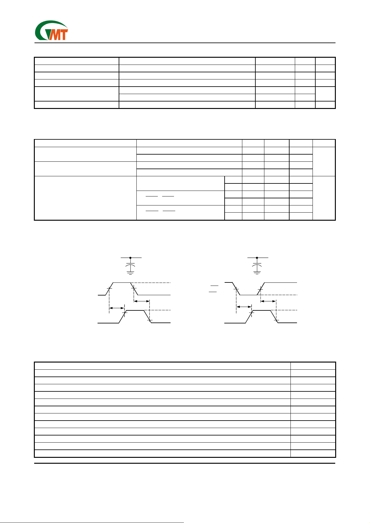
Logic Section
PARAMETER TEST CONDITION* MIN MAX UNIT
Logic input current 1 µA
Logic input high level 2 V
Logic input low level 0.8 V
Logic output high level
VCC5=5V, IO=1mA VCC5 -0.4
VCC5=0V, I
=1mA, VCC3=3.3V VCC3 -0.4
O
V
Logic output low level IO=1mA 0.4 V
*Pulse-testing techniques maintain junction temperature close to ambient temperatures; thermal effects must be taken into account sepa-
rately.
Switching Characteristics **
PARAMETER TEST CONDITION MIN TYP MAX UNIT
t
Rise times, output
r
t
Fall times, output
f
V
V
V
V
VI (
t
Propagation delay
pd
(see Figure 1)
VI (
V
**Switching Characteristics are with CL = 147µF.
§ Refer to Parameter Measurement Information
O (AVCC/BVCC)
O (AVPP/BVPP)
O (AVCC/BVCC)
O (AVPP/BVPP)
AVPPD0/BVPPD0
(
I
2.6
10
7.5
ms
38
) to V
O (AVPP/BVPP)
/
) to V
1AVCCD
1BVCCD
O (AVCC/BVCC)
/
0AVCCD
) to V
0BVCCD
O (AVCC/BVCC)
(3.3V)
(5V)
ton 14
44
t
off
ton 3.2
17
t
off
ton 4.4
20
t
off
ms
Parameter Measurement Information
AVCC
LOAD CIRCUIT
50%
)
t
on
VOLTAGE WAVEFORMS
90%
C
50%
L
V
DD
t
off
10%
GND
V
GND
I(3.3V)
FIGURE
(V
V
I(VPPD1)
V
I(VPPD0)
O(AVPP)
=0V)
AVPP
50%
t
on
VOLTAGE WAVEFORMS
C
LOAD CIRCUIT
50%
90%
L
V
DD
t
off
10%
GND
V
GND
I(12V)
V
I(VCCD1)
(V
I(VCCD0)=VDD
V
O(AVCC)
Figure 1. Test Circuits and Voltage Waveforms
Table of Timing Diagrams
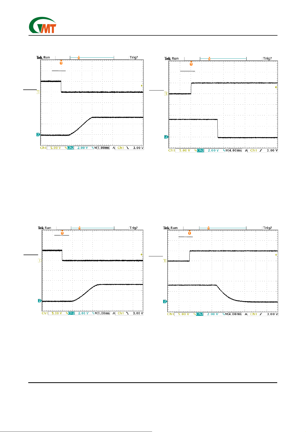
AVCC/BVCC Propagation Delay and Rise Time W ith 1µF Load, 3.3V Switch 2
AVCC/BVCC Propagation Delay and Fall Time W ith 1µF Load, 3.3V Switch 3
AVCC/BVCC Propagation Delay and Rise Time W ith 147µF Load, 3.3V Switch 4
AVCC/BVCC Propagation Delay and Fall Time W ith 147µF Load, 3.3V Switch 5
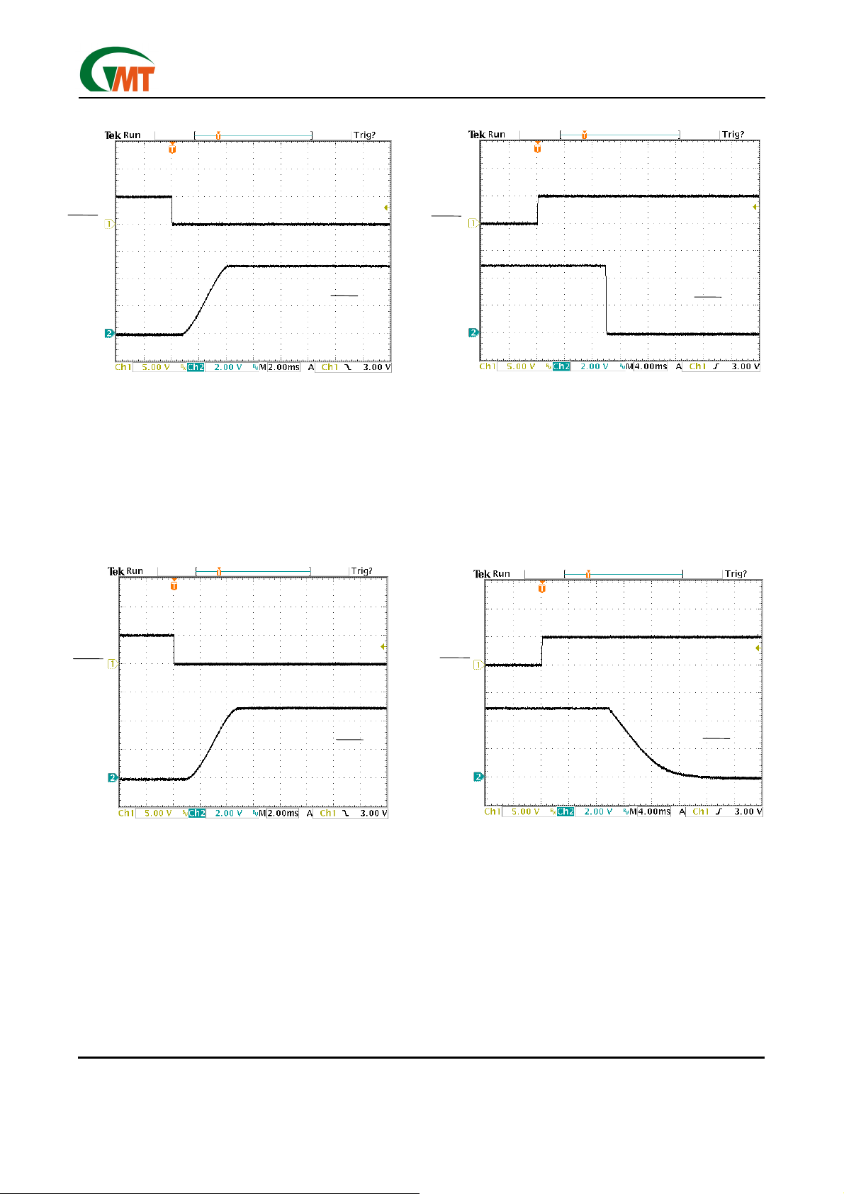
AVCC/BVCC Propagation Delay and Rise Time W ith 1µF Load, 5V Switch 6
AVCC/BVCC Propagation Delay and Fall Time W ith 1µF Load, 5V Switch 7
AVCC/BVCC Propagation Delay and Rise Time W ith 147µF Load, 5V Switch 8
AVCC/BVCC Propagation Delay and Fall Time W ith 147µF Load, 5V Switch 9
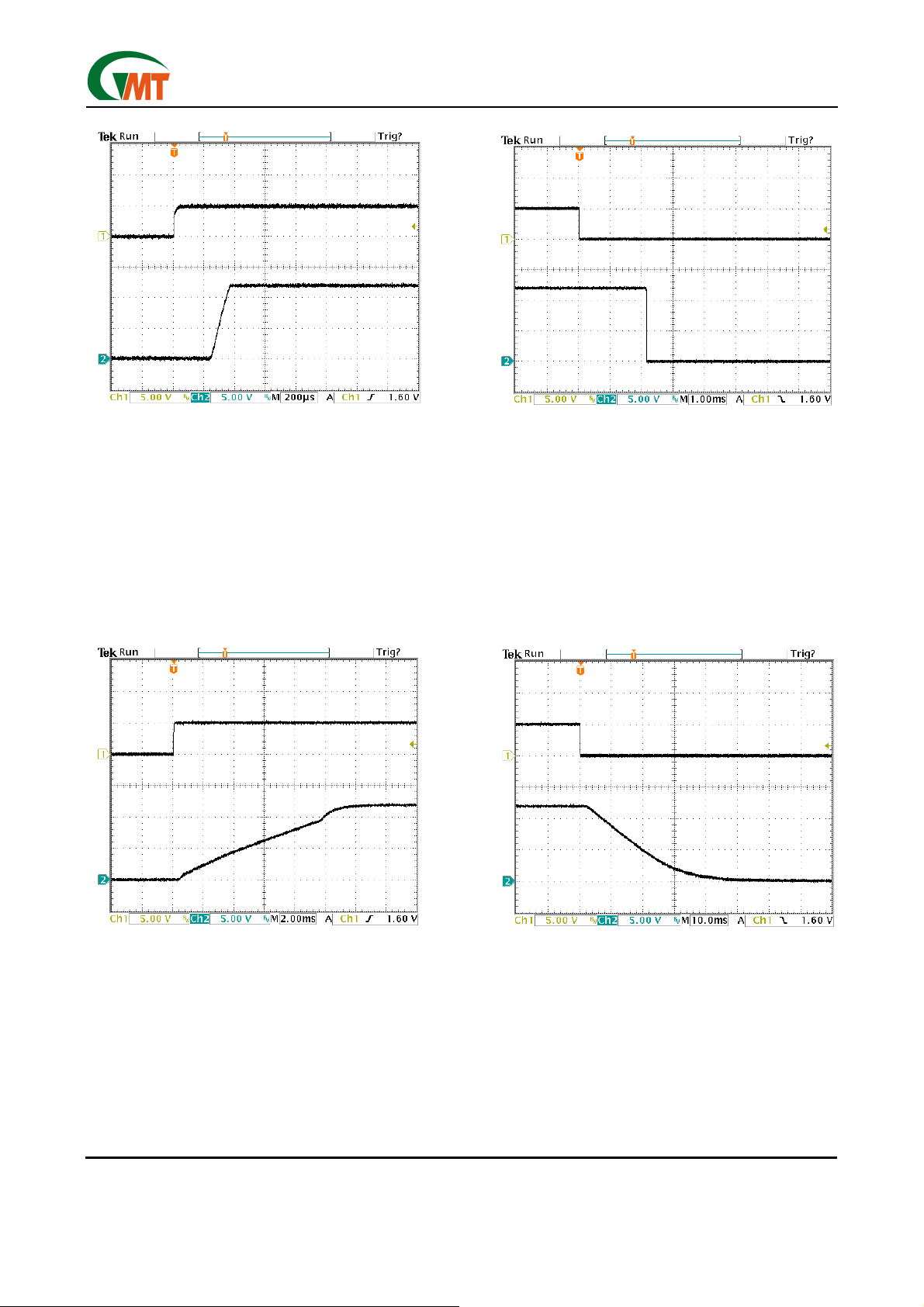
AVPP/BVPP Propagation Delay and Rise Time W ith 1µF Load, 12V Switch 10
AVPP/BVPP Propagation Delay and Fall Time W ith 1µF Load, 12V Switch 11
AVPP/BVPP Propagation Delay and Rise Time With 147µF Load, 12V Switch 12
AVPP/BVPP Propagation Delay and Fall Time W ith 147µF Load, 12V Switch 13
Ver: 1.0
Jan 23, 2003
4
TEL: 886-3-5788833
http://www.gmt.com.tw
Page 5
Global Mixed-mode Technology Inc.
Parameter Measurement Information
VCCD0=3.3V
VCCD1
AVC C
Figure 2. AVCC/BVCC Propagation Delay and Rise
Time With 1µF Load, 3.3V Switch
G576
VCCD0=3.3V
VCCD1
AVC C
Figure 3. AVCC/BVCC Propagation Delay and Fall
Time With 1µF Load, 3.3V Switch
VCCD0=3.3V
VCCD1
AVC C
Figure 4. AVCC/BVCC Propagation Delay and Rise
Time With 147µF Load, 3.3V Switch
VCCD0=3.3V
VCCD1
AVC C
Figure 5. AVCC/BVCC Propagation Delay and Fall
Time With 147µF Load, 3.3V Switch
Ver: 1.0
Jan 23, 2003
5
TEL: 886-3-5788833
http://www.gmt.com.tw
Page 6
A
A
A
A
Global Mixed-mode Technology Inc.
VCCD0
VCCD1=5V
VCC
Figure 6. AVCC/BVCC Propagation Delay and Rise
Time With 1µF Load, 5V Switch
G576
VCCD0
VCCD1=5V
VCC
Figure 7. AVCC/BVCC Propagation Delay and Fall
Time With 1µF Load, 5V Switch
VCCD0
VCCD1=5V
VCC
Figure 8. AVCC/BVCC Propagation Delay and Rise
Time with 147µF Load, 5V Switch
Ver: 1.0
Jan 23, 2003
VCCD0
VCC
Figure 9. AVCC/BVCC Propagation Delay and Fall
Time with 147µF Load, 5V Switch
TEL: 886-3-5788833
http://www.gmt.com.tw
6
VCCD1=5V
Page 7
Global Mixed-mode Technology Inc.
VPPD0
VPPD1=0V
AVPP
Figure 10. AVPP/BVPP Propagation Delay and Rise
Time With 1µF Load, 12V Switch
G576
VPPD0
VPPD1=0V
AVPP
Figure 11. AVPP/BVPP Propagation Delay and Fall
Time With 1µF Load, 12V Switch
VPPD0
VPPD1=0V
AVPP
Figure 12. AVPP/BVPP Propagation Delay and Rise
Time With 147µF Load, 12V Switch
Ver: 1.0
Jan 23, 2003
VPPD0
AVPP
Figure 13. AVPP/BVPP Propagation Delay and Fall
Time With 147µF Load, 12V Switch
TEL: 886-3-5788833
http://www.gmt.com.tw
7
VPPD1=0V
Page 8

Global Mixed-mode Technology Inc.
Application Information
Overview
PC Cards were initially introduced as a means to add
EEPROM (flash memory) to portable computers with
limited onboard memory. The idea of add-in cards
quickly took hold; modems, wireless LANs, Global
Positioning Satellite (GPS) systems, multimedia, and
hard-disk versions were soon available. As the number of PC Card applications grew, the engineering
community quickly recognized the need for a standard
to ensure compatibility across platforms. To this end,
the PCMCIA (Personal Computer Memory Card International Association) was established, comprised of
members from leading computer, software, PC Card,
and semiconductor manufactures. One key goal was
to realize the “plug and play” concept, i.e. cards and
termi-
PP
,
CC
hosts from different vendors should be compatible.
PC Card Power Specification
System compatibility also means power compatibility.
The most current set of specifications (PC Card Standard) set forth by the PCMCIA committee states that
power is to be transferred between the host and the
card through eight of the 68 terminals of the PC Card
connectors. This power interface consists of two V
two V
, and four ground terminals. Multiple VCC and
PP
ground terminals minimize connector-terminal and line
resistance. The two V
terminals were originally
PP
specified as separate signals but are commonly tied
together in the host to form a single node to minimize
voltage losses. Card primary power is supplied
through the V
terminals; flash-memory programming
CC
and erase voltage is supplied through the V
nals.
Designing for Voltage Regulation
The current PCMCIA specification for output voltage
regulation of the 5V output is 5% (250mV). In a typical
PC power-system design, the power supply will have an
output voltage regulation (V
) of 2% (100mV). Also,
PS(reg)
a voltage drop from the power supply to the PC Card
will result from resistive losses (V
) in the PCB traces
PCB
and the PCMCIA connector. A typical design would limit
the total of these resistive losses to less than 1% (50mV)
of the output voltage. Therefore, the allowable voltage
drop (V
) for the G576 would be the PCMCIA voltage
DS
regulation less the power supply regula-tion and less
the PCB and connector resistive drops:
= V
V
DS
O(reg)-VPS(reg)-VPCB
Typically, this would leave 100mV for the allowable
voltage drop across the G576. The voltage drop is the
output current multiplied by the switch resistance of
the G576. Therefore, the maximum output current that
can be delivered to the PC Card in regulation is the
allowable voltage drop across the G576 divided by the
output switch resistance.
max = V
I
O
DS
/ R
DS(on)
The AVCC/BVCC outputs deliver 1A continuous at
3.3V and 5.5V within regulation over the operating
Ver: 1.0
Jan 23, 2003
G576
temperature range. Using the same equations, the
PCMCIA specification for output voltage regulation of
the 3.3V output is 300mV. Using the voltage drop percentages for power supply regulation (2%) and PCB
resistive loss (1%), the allowable voltage drop for the
3.3V switch is 200mV. The 12V outputs AVPP/BVPP
of the G576 can deliver 150mA continuously.
Overcurrent and overtemperature protection
PC Cards are inherently subuect to damage from mishandling. Host systems require protection against
short-circuited cards that could lead to power supply or
PCB trace damage. Even systems sufficiently robust
to withstand a short circuit would still undergo rapid
battery discharge into the damaged PC Card, resulting
in a sudden loss of system power. Most hosts include
fuses for protection. The reliability of fused systems is
poor, and requires troubleshooting and repair, usually
by the manufacturer. When fuses are blown.
The G576 uses sense FETs to check for overcurrent
conditions in each of the AVCC/BVCC and AVPP/
BVPP outputs.Unlike sense resistors or polyfuses,
these FETs do not add to the series resistance of the
switch; therefore voltage and power losses are reduced. Overcurrent sensing is applied to each output
separately. When an overcurrent condition is detected,
only the power output affected is limited; all other
power outputs continue to function normally. The
AOC/BOC
indicator, normally a ligic high, are a logic
low when an overcurrent condition is detected providing for initiation of system diagnostics and/or sending
a warning message to the user.
During power up, the G576 controls the rise time of
the AVCC/BVCC and AVPP/BVPP outputs and limits
the current into a faulty card or connector. If a short
circuit is applied after power is established (e.g., hot
insertion of a bad card), current is initially limited only
by the impedance between the short and the power
supply. In extreme cases, as much as 10A to 15A may
flow into the short before the current limiting of the
G576 engages. If the AVCC/BVCC or AVPP/BVPP
outputs are driven below ground, the G576 may latch
nondestructively in an off state, Cycling power will reestablish normal operation.
Overcurrent limiting for the AVCC/BVCC outputs is
designed to activate if powered up into a short in the
range of 0.8A to 2.2A, typically at about 1.5A. The
AVPP/BVPP outputs limit from 120mA to 400mA, typically around 200mA. The protection circuitry acts by
linearly limiting the current passing through the switch
rather than initiating a full shutdown of the supply.
Shutdown occurs only during thermal limiting.
Thermal limiting prevents destruction of the IC from
overheating if the package power dissipation rating are
exceeded. Thermal limiting disables power output until
the device has cooled.
TEL: 886-3-5788833
http://www.gmt.com.tw
8
Page 9

Global Mixed-mode Technology Inc.
12V Supply Not Required
Most PC Card switches use the externally supplied
12V to power gate drive and other chip functions,
which require that power be present at all times. The
G576 offers considerable power savings by using an
internal charge pump to generate the required higher
voltages from 5V input; Therefore, the external 12V
supply can be disable except when needed for
flash-memory functions, thereby extending battery
lifetime. Do not ground the 12V switch inputs when the
12-V input is not used. Additional power savings are
realized by the G576 during a software shutdown in
which quiescent current drops to a maximum of 3µA.
3.3V Low Voltage Mode
The G576 will operates in a 3.3V low voltage mode
when 3.3V is only available input voltage (VCC5=0).
This allows host and PC Cards to be operated in
low-power 3.3V-only modes such as sleep modes or
pager modes. Note that in these operation mode, the
G576 will derive its bias current from the 3.3V input pin
and only 3.3V can be delivered to the PC Card.
Voltage Transitioning Requirement
PC Cards are migrating from 5V to 3.3V to minimize
power consumption, optimize board space, and increase logic speeds. The G576 meets all combinations of power delivery as currently defined in the
PCMCIA standard. The latest protocol accommodates
mixed 3.3V/5V systems by first powering the card with
5V, then polling it to determine its 3.3V compatibility.
The PCMCIA specification requires that the capacitors
on 3.3V-compatible cards be discharged to below 0.8V
before applying 3.3V power. This function is a power
reset and ensures that sensitive 3.3V circuitry is not
G576
subjected to any residual 5V charge. The G576 offer a
selectable V
with PCMCIA 3.3V/5V switching specifications.
Output Ground Switches
PC Card specification requires that AVCC/BVCC be
discharged within 100 ms. PC Card resistance can not
be relied on to provide a discharge path for voltages
stored on PC Card capacitance because of possible
high-impedance isolation by power-management
schemes.
Power Supply Considerations
The G576 has multiple pins for each of its 3.3V, and
5V power inputs and for switched AVCC/BVCC outputs. Any individual pin can conduct the rated input or
output current. Unless all pins are connected in parallel, the series resistance is significantly higher than
that specified, resulting in increased voltage drops and
lost power. it is recommended that all input and output
power pins be paralleled for optimum operation.
To increase the noise immunity of the G576, the
power supply inputs should be bypassed with a 1µF
electrolytic or tantalum capacitor paralleled by a
0.047µF to 0.1µF ceramic capacitor. It is strongly
recommended that the switched outputs be bypassed
with a 0.1µF or larger, ceramic capacitor; doing so
improves the immunity of the G576 to electrostatic
discharge (ESD). Care should be taken to minimize
the inductance of PCB traces between the G576 and
the load. High switching currents can produce large
negative voltage transients, which forward biases substrate diodes, resulting in unpredictable performance.
Similary, no pin should be taken below -0.3V.
and VPP ground state, in accordance
CC
Ver: 1.0
Jan 23, 2003
9
TEL: 886-3-5788833
http://www.gmt.com.tw
Page 10
Global Mixed-mode Technology Inc.
G576
G576
3.3V
3.3V
3.3V
3.3V
12V
12V
CPU
CPU
Controller
Controller
5V
5V
5V
5V
G576
S1
S1
S2
S2
S3
S3
ASHDN
ASHDN
BSHDN
BSHDN
AVPPD0
AVPPD0
AVPPD1
AVPPD1
AVCCD0
AVCCD0
AVCCD1
AVCCD1
BVPPD0
BVPPD0
BVPPD0
BVPPD0
BVCCD0
BVCCD0
BVCCD1
BVCCD1
AOC
AOC
BOC
BOC
cs
cscs
S4
S4
S5
S5
S6
See Note A
See Note A
Thermal
Thermal
S6
cs
cscs
GND
GND
V
V
V
V
V
V
V
V
CC2
PP1
PP1
PP2
PP2
CC1
CC1
CC2
Card A
Card A
See Note A
See Note A
S10
12V
12V
5V
5V
5V
5V
3.3V
3.3V
3.3V
3.3V
cs
cscs
S7
S7
S8
S8
S9
S9
cs
cscs
S10
S11
S11
S12
S12
V
V
PP2
PP2
V
V
PP1
PP1
V
V
CC2
CC2
V
V
Card B
Card B
CC1
CC1
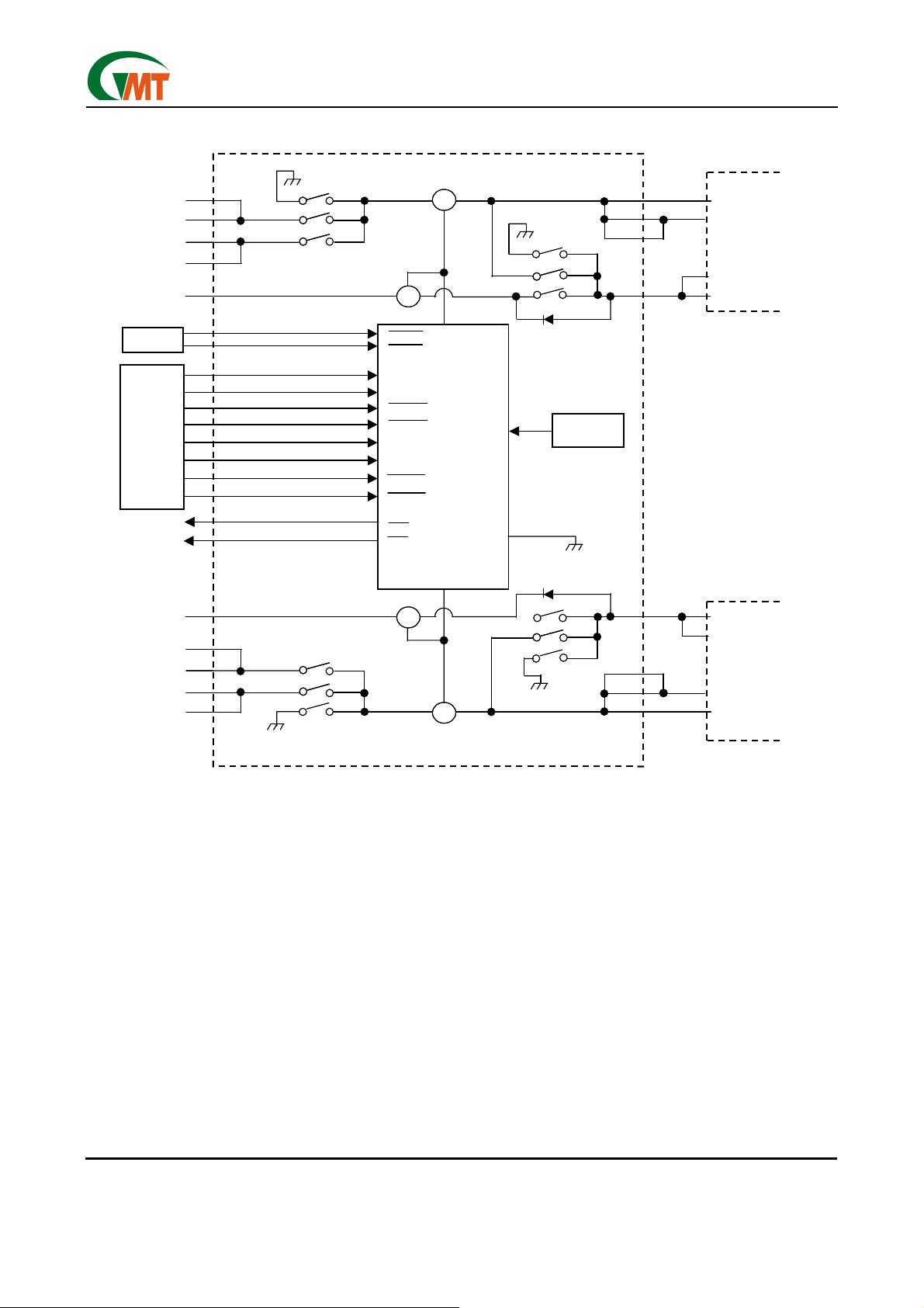
Note : MOSFET switch S6/S10 has a back-gate diode from the source to the drain. Unused switch inputs should
never be grounded.
Figure 14. Internal Switching Matrix
Ver: 1.0
Jan 23, 2003
10
TEL: 886-3-5788833
http://www.gmt.com.tw
Page 11
Global Mixed-mode Technology Inc.
G576
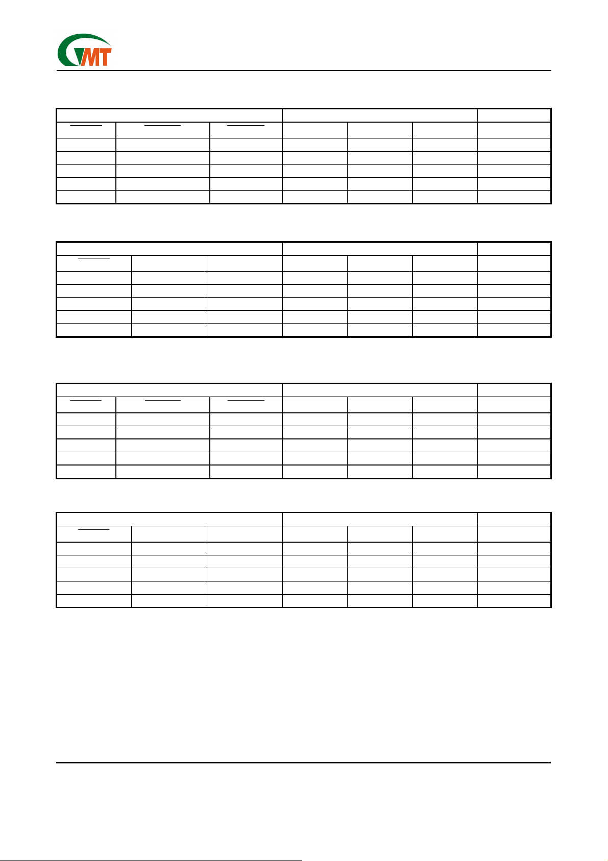
G576 Control Logic
AVCC
CONTROL SIGNALS INTERNAL SWITCH SETTINGS OUTPUT
ASHDN
AVPP
* Output depends on AVCC
1 0 0 CLOSED OPEN OPEN 0V
1 0 1 OPEN CLOSED OPEN 3.3V
1 1 0 OPEN OPEN CLOSED 5V
1 1 1 CLOSED OPEN OPEN 0V
0 × × OPEN OPEN OPEN Hi-Z
ASHDN
1 0 0 CLOSED OPEN OPEN 0V
1 0 1 OPEN CLOSED OPEN AVCC*
1 1 0 OPEN OPEN CLOSED VPP (12V)
1 1 1 OPEN OPEN OPEN Hi-Z
0 × × OPEN OPEN OPEN Hi-Z
AVCCD1
CONTROL SIGNALS INTERNAL SWITCH SETTINGS OUTPUT
AVPPD0 AVPPD1 S4 S5 S6 AVPP
AVCCD0
S1 S2 S3 AVCC
BVCC
CONTROL SIGNALS INTERNAL SWITCH SETTINGS OUTPUT
BSHDN
1 0 0 CLOSED OPEN OPEN 0V
1 0 1 OPEN CLOSED OPEN 3.3V
1 1 0 OPEN OPEN CLOSED 5V
1 1 1 CLOSED OPEN OPEN 0V
0 × × OPEN OPEN OPEN Hi-Z
BVCCD1
BVCCD0
S7 S8 S9 BVCC
BVPP
CONTROL SIGNALS INTERNAL SWITCH SETTINGS OUTPUT
BSHDN
* Output depends on BVCC
1 0 0 CLOSED OPEN OPEN 0V
1 0 1 OPEN CLOSED OPEN BVCC*
1 1 0 OPEN OPEN CLOSED VPP (12V)
1 1 1 OPEN OPEN OPEN Hi-Z
0 × × OPEN OPEN OPEN Hi-Z
BVPPD0 BVPPD1 S10 S11 S12 BVPP
Ver: 1.0
Jan 23, 2003
11
TEL: 886-3-5788833
http://www.gmt.com.tw
Page 12
Global Mixed-mode Technology Inc.
G576
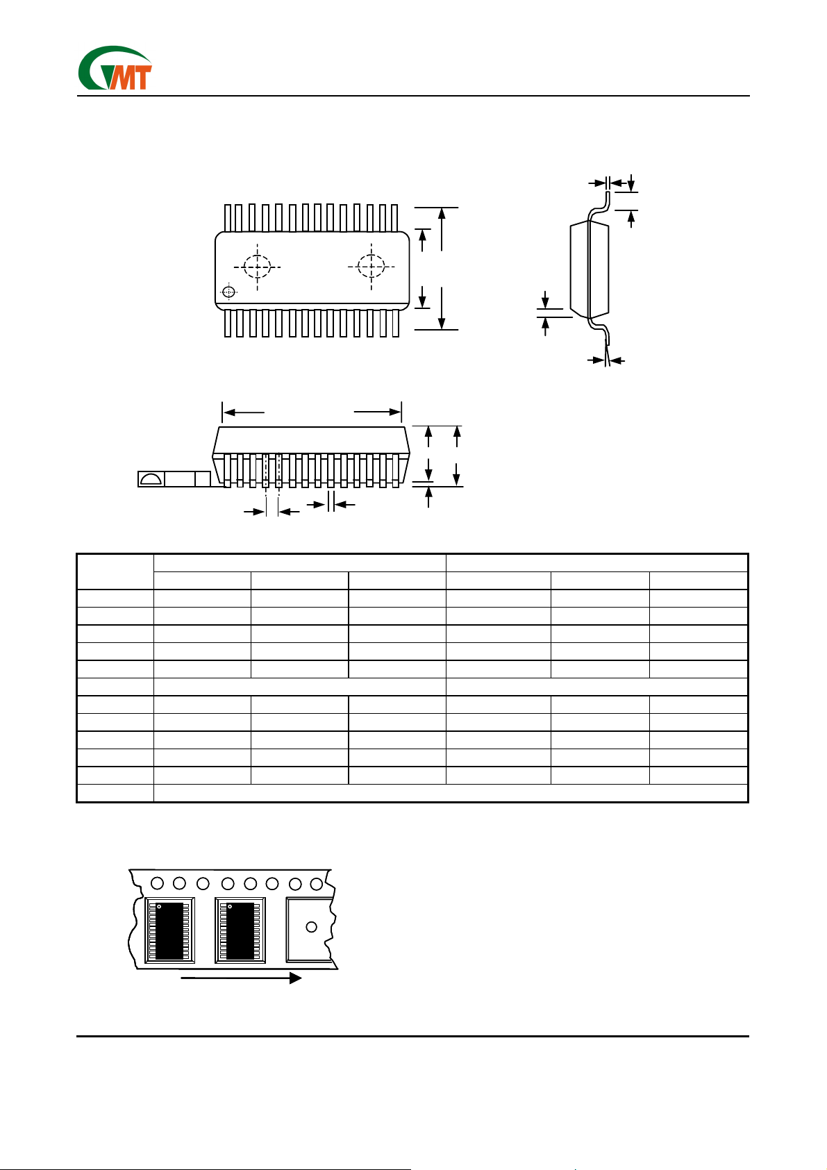
Package Information
C
L
E1
C
0.004
SEATING PLANE
E
D
A2
A
A1
e
b
h x 45
°
θ
SYMBOL
A 2.0 0.079
A1 0.05 0.002
A2 1.65 1.75 1.85 0.065 0.069 0.073
b 0.22 0.30 0.33 0.009 0.012 0.013
c 0.09 0.15 0.21 0.004 0.006 0.008
e 0.65 BASIC 0.026 BASIC
D 9.90 10.20 10.50 0.390 0.402 0.413
E 7.40 7.80 8.20 0.291 0.307 0.323
E1 5.00 5.30 5.60 0.197 0.209 0.220
L 0.55 0.75 0.95 0.022 0.030 0.038
θ
JEDEC MO-150 (AH)
MIN. NOM. MAX. MIN. NOM. MAX.
DIMENSION IN MM DIMENSION IN INCH
0 4 8 0 4 8
Taping Specification
Feed Direction
Typical SSOP Package Orientation
Typical SSOP Package Orientation
GMT Inc. d oes not assume any responsibility for use of any circuitry described, no circuit patent licenses are implied and GMT Inc. reserves the right at any time without notice to change said circuitry and specifications.
Ver: 1.0
Jan 23, 2003
Feed Direction
12
TEL: 886-3-5788833
http://www.gmt.com.tw
 Loading...