

Page 1

Ver 3.1
Oct 03, 2001
TEL: 886-3-5788833
http://www.gmt.com.tw
1
G261
Global Mixed-mode Technology Inc.
Low Voltage Differential (LVD) SCSI 27 Line Regulator Set
Features
SCSI SPI-2 (Ultra 2) LVD SCSI 27 Line Low Voltage Differential Regulator
4.0V to 5.25V Operation
Integrated Regulator Set for LVD SCSI
Differential Failsafe Bias
Applications
SCSI cable
SCSI card
Disk Array
Industrial PC
POS
Description
The G261 LVD Regulator set is designed to provide
the correct reference voltages and bias currents for
LVD termination resistor networks (475Ω, 121Ω,and
475Ω) The device also provides a 1.3V output for
DIFFSENSE signaling. With the proper resistor network, the G261 solution will meet the common mode
impedance, differential mode impedance, differential
bias voltage and common mode voltage requirements
of SPI-2 (Ultra2).
This device contains two sink / source reference voltage regulators, a 1.3V buffered output and protection
features. The protection features include thermal
shutdown and active current limiting circuitry. The
G261 is offered in 16pin SOP.
Ordering Information
PART TEMP. RANGE PIN-PACKAGE
G261P1 -40°C~80°C 8 Pin SOP
Pin Configuration
REG2
HSPGND
HSPGND
REG1
2
3
4
8
7
6
5
8 Pin SOP
TERMPWR
HSGND
HSGND
DIFFSENSE
1
REG2
HSPGND
HSPGND
REG1
2
3
4
8
7
6
5
8 Pin SOP
TERMPWR
HSGND
HSGND
DIFFSENSE
1
Page 2

Ver 3.1
Oct 03, 2001
TEL: 886-3-5788833
http://www.gmt.com.tw
2
G261
Global Mixed-mode Technology Inc.
Absolute Maximum Ratings
TERMPWR…………….……….……………….……6V
Package Dissipation…………………….…………..1W
Junction Temperature…………..…….-55
°
C
to 150
°
C
Storage Temperature…………………-65
°
C
to 150
°
C
Recommended Operating Conditions
TERMPWR Voltage…….………………4.0V to 5.25V
Electrical Characteristics
Unless otherwise specified these specifications apply for TA= 0℃ to 70℃,TERMPWR=5V.
PARAMETER TEST CONDITIONS MIN TYP MAX UMITS
TERMPWR Supply Current Section
TERMPWR Supply Current No Load 6 10.0 mA
TERMPWR Voltage 4.0 5.25 V
Regulator Section
1.75 Volt Regulator
REG1(±50mA)
1.7 1.75 1.8 V
1.3 Volt Regulator DIFFSENSE, No Load 1.2 1.3 1.4 V
0.75 Volt Regulator
REG2(±50mA)
0.7 0.75 0.8 V
1.75 Volt Regulator Source Current -50 mA
1.75 Volt Regulator Sink Current 50 mA
1.75 Sink Current Limit 600 mA
1.75 Source Current Limit -600 mA
1.3 Volt Regulator Source Current DIFFSENSE, GND -5 -15 mA
1.3 Volt Regulator Sink Current DIFFSENSE, 2.4V 10 200
μ
A
0.75 Volt Regulator Source Current -50 mA
0.75 Volt Regulator Sink Current 50 mA
0.75 Current Limit 600 mA
0.75 Current Limit -600 mA
Block Diagram
REF 1.75V
REF 0.75V
REF 1.3V
5mA SOURCE/10µA SINK
1.75V±50mV
50mA SOURCE/SINK
TRMPWR
4.0V to 5.25V
PGND
0.75V±50mV
50mA SOURCE/SINK
1.3V±0.1V
DIFFSENSE
REG1
REG2
SOURCE/SINK REGULATOR
REF 1.75V
REF 0.75V
REF 1.3V
5mA SOURCE/10µA SINK
1.75V±50mV
50mA SOURCE/SINK
TRMPWR
4.0V to 5.25V
PGND
0.75V±50mV
50mA SOURCE/SINK
1.3V±0.1V
DIFFSENSE
REG1
REG2
SOURCE/SINK REGULATOR
Page 3
Ver 3.1
Oct 03, 2001
TEL: 886-3-5788833
http://www.gmt.com.tw
3
G261
Global Mixed-mode Technology Inc.
Application Information
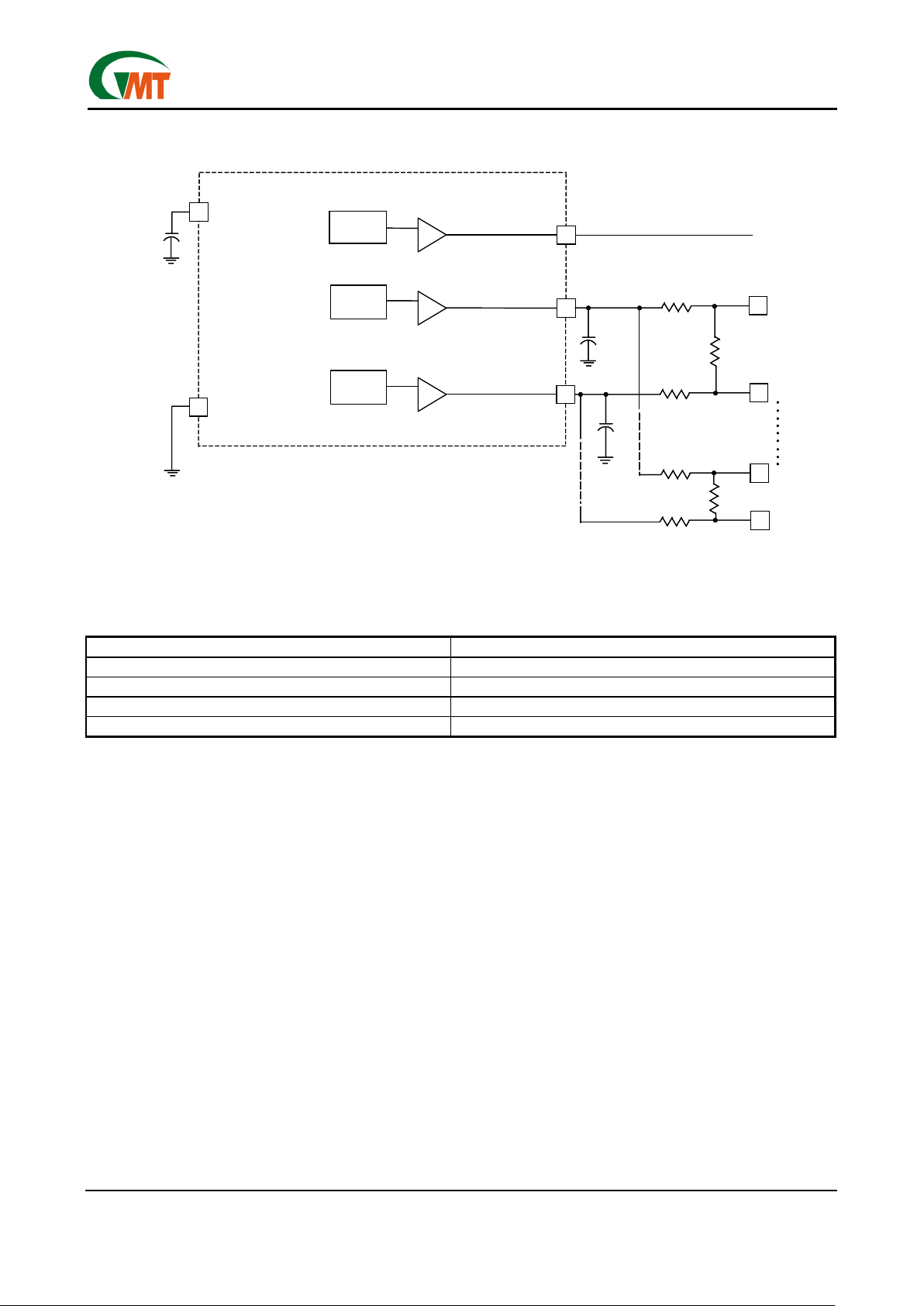
Figure 1. LVD SCSI Discrete Resistor Stack
Table1. Resistor Network v.s Standard
Outputs Specification
107.3Ω Diff 100Ω to 110Ω
112.9mV Diff Bias 100mV to 125mV
237Ω Common Mode 100Ω to 300Ω
1.25V Common Mode 1.2V to 1.30V
Application Note:
The resistor network, along with the 1.75V and 0.75V references will give the correct dif-
ferential impedance, bias voltage, common mode impedance and common mode voltage as show in Table 1.
Layout guideline:
1. For stable operation, the 1µF capacitor on TERMPWR pin and 4.7µF capacitors on REG1 and REG2
pins must be placed within 0.25 inch of their respective pins.
2. The PCB trace length form Lx- and Lx+ to the connector pins (all 27pairs) must be of equal length, in order
to minimize the signal skew among these pairs. In addition, these traces must be as short as possible, in
order to minimize capacitance.
REF
1.3V
SOURCE/SINK REGULAT OR
50 mA SOURCE/S INK
TERMPWR
50 mA SOURCE /SINK
DIFFSENSE
REG1
REG2
SOURCE 5 to 15mA
REF
1.75V
REF
0.75V
SOURCE/SINK REGULAT OR
4.7µF
4.7µF
121 1%
121 1%
L1-
L1+
L27-
L27+
475 1%
475 1%
475 1%
PGND
475 1%
1.3V ±0.1V
1.75V ±50mV
0.75V ±50mV
1µF
DIFFSENSE: SOURCE ONLY
FROM TERMPWR
to DIFFSENS pin
REF
1.3V
SOURCE/SINK REGULAT OR
50 mA SOURCE/S INK
TERMPWR
50 mA SOURCE /SINK
DIFFSENSE
REG1
REG2
SOURCE 5 to 15mA
REF
1.75V
REF
0.75V
SOURCE/SINK REGULAT OR
4.7µF
4.7µF
121 1%
121 1%
L1-
L1+
L27-
L27+
475 1%
475 1%
475 1%
PGND
475 1%
1.3V ±0.1V
1.75V ±50mV
0.75V ±50mV
1µF
DIFFSENSE: SOURCE ONLY
FROM TERMPWR
to DIFFSENS pin
Page 4
Ver 3.1
Oct 03, 2001
TEL: 886-3-5788833
http://www.gmt.com.tw
4
G261
Global Mixed-mode Technology Inc.
Package Information
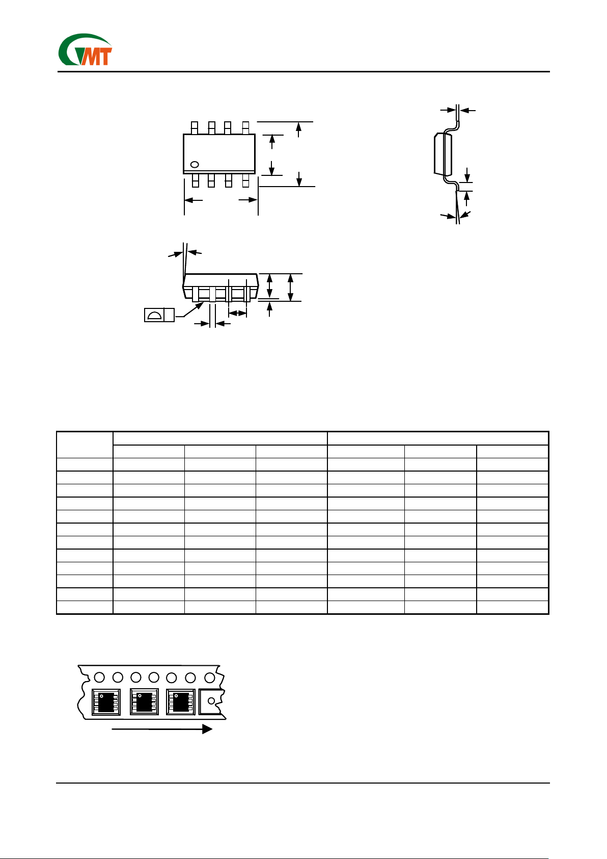
8-Pin SOP
Note:
1.Package body sizes exclude mold flash and gate burrs
2.Dimension L is measured in gage plane
3.Tolerance 0.10mm unless otherwise specified
4.Controlling dimension is millimeter converted inch dimensions are not necessarily exact.
DIMENSION IN MM DIMENSION IN INCH
SYMBOL
MIN. NOM. MAX. MIN. NOM. MAX.
A 1.35 1.60 1.75 0.053 0.063 0.069
A1 0.10 ----- 0.25 0.004 ----- 0.010
A2 ----- 1.45 ----- ----- 0.057 -----
B 0.33 ----- 0.51 0.013 ----- 0.020
C 0.19 ----- 0.25 0.007 ----- 0.010
D 4.80 ----- 5.00 0.189 ----- 0.197
E 3.80 ----- 4.00 0.150 ----- 0.157
e ----- 1.27 ----- ----- 0.050 -----
H 5.80 ----- 6.20 0.228 ----- 0.244
L 0.40 ----- 1.27 0.016 ----- 0.050
y ----- ----- 0.10 ----- ----- 0.004
θ
0º ----- 8º 0º ----- 8º
Taping Specification
GMT Inc. d oes not assume any responsibility for use of any circuitry described, no circuit patent licenses are implied and GMT Inc. reserves the right at any time without notice to change said circuitry and specifications.
D
E
H
7 °(4X)
A1
A2
A
e
B
y
C
L
θ
D
E
H
7 °(4X)
A1
A2
A
e
B
y
C
L
θ
Feed Direction
Typical SOP Package Orientation
Feed Direction
Typical SOP Package Orientation
 Loading...