

Page 1
FSAV430
Low Voltage 1.1GHz 4 Channel 2:1 Video Switch
FSAV430 Low Voltage 1.1GHz 4 Channel 2:1 Video Switch
December 2004
Revised August 2005
General Description
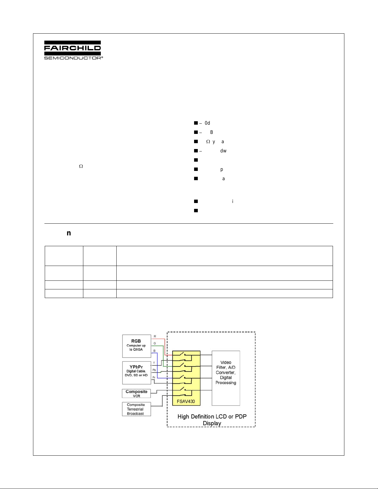
The FSAV430 is a high performance Quad SPDT (2-to-1 multiplexer/demultiplexer) video switch designed specifically for
switching high definition YPbPr and computer RGB (up to
UXGA) signals. The bandwidth of this device is 1.1GHz (Typ)
which allows signals to pass with minimal edge and phase distortion. Image integrity is maintained with low crosstalk, high
OFF-Isolation and low differential gain and phase. The low On
:
Resistance (4.5
voltage operation (3V), low power consumption (1uA maximum)
and small scale packaging (including leadless DQFN) make this
device ideal for a broad range of applications.
typical) minimizes signal insertion loss. Low
Features
O
40dB OFF Isolation at 30MHz
O
60dB non-adjacent channel crosstalk at 30MHz
O
4.5: typical On Resistance (RON)
O
3dB bandwidth: 1.1GHz
O
Low power consumption (1uA max)
O
Control input: TTL compatible
O
Bidirectional operation
Applications
O
RGB Video Switch in LCD, plasma and projection displays
O
DVD-RW
Ordering Code:
Order Package
Number Number
FSAV430BQX
(Note 1)
FSAV430QSC MQA16A 16-Lead Quarter Size Small Outline Package (QSOP), JEDEC MO-137, 0.150" Wide
FSAV430MTC MTC16 16-Lead Thin Shrink Small Outline Package (TSSOP), JEDEC MO-153, 4.4mm Wide
MLP016E Pb-Free 16-Terminal Depopulated Quad Very-Thin Flat Pack No Leads (DQFN), JEDEC MO-241,
2.5 x 3.5mm
Package Description
Devices also available in Tape and Reel. Specify by appending suffix letter “X” to the ordering code.
Pb-Free package per JEDEC J-STD-020B.
Note 1: DQFN package available in Tape and Reel only.
© 2005 Fairchild Semiconductor Corporation DS500890 www.fairchildsemi.com
Page 2
Analog Symbol
Connection Diagrams
FSAV430
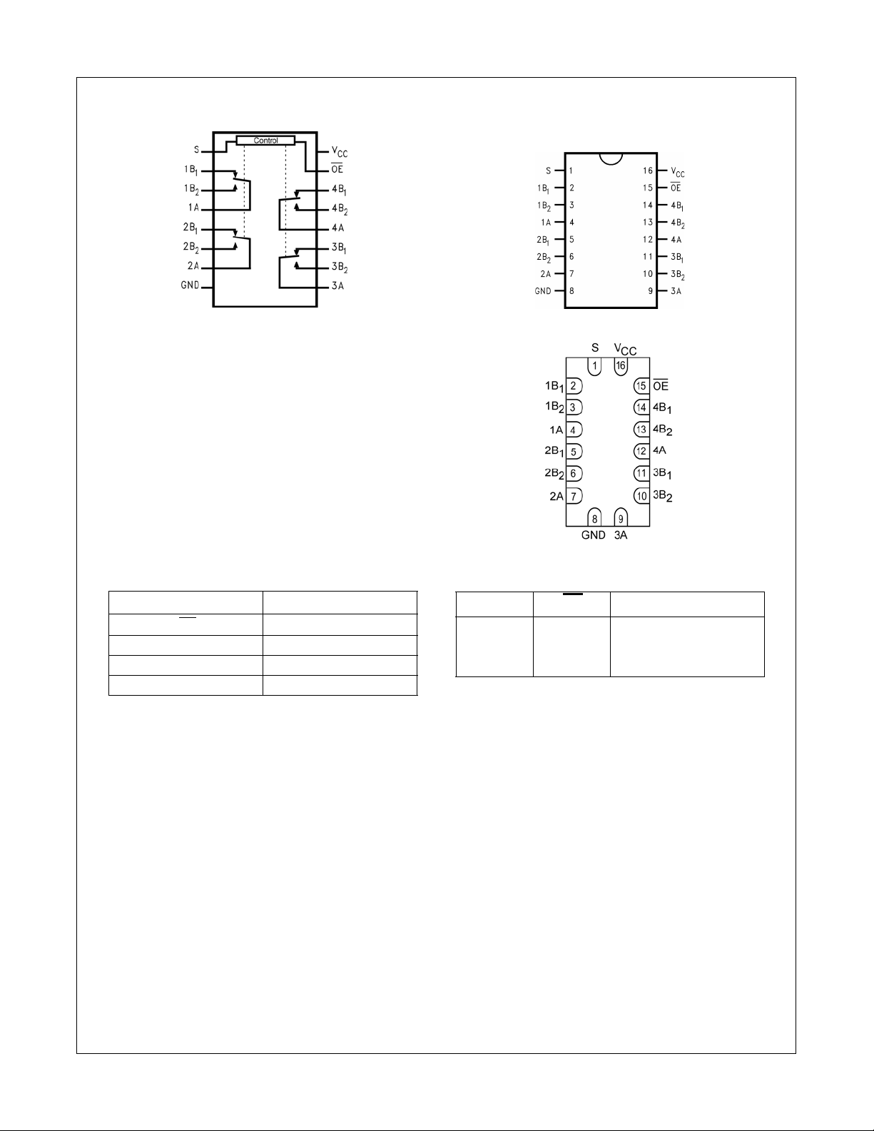
Pin Assignments for QSOP and TSSOP
Pad Assignments for DQFN
Pin Descriptions
Pin Name Description
OE Bus Switch Enable
S Select Input
ABus A
B
1–B2
Bus B
Truth Table
SOE Function
X H Disco nnect
LL A = B
HL A = B
1
2
www.fairchildsemi.com 2
Page 3
FSAV430
Absolute Maximum Ratings(Note 2)
Supply Voltage (VCC)
DC Switch Voltage (V
DC Input Voltage (V
DC Input Diode Current (l
DC Output (I
DC V
OUT
/GND Current (ICC/I
CC
Storage Temperature Range (T
)
S
) (Note 3)
IN
) VIN 0V
IK
) Sink Current 128 mA
)
GND
)
STG
ESD
Human Body Model 4kV
0.5V to 4.6V
0.5V to VCC 0.05V
0.5V to 4.6V
65q
C to 150 qC
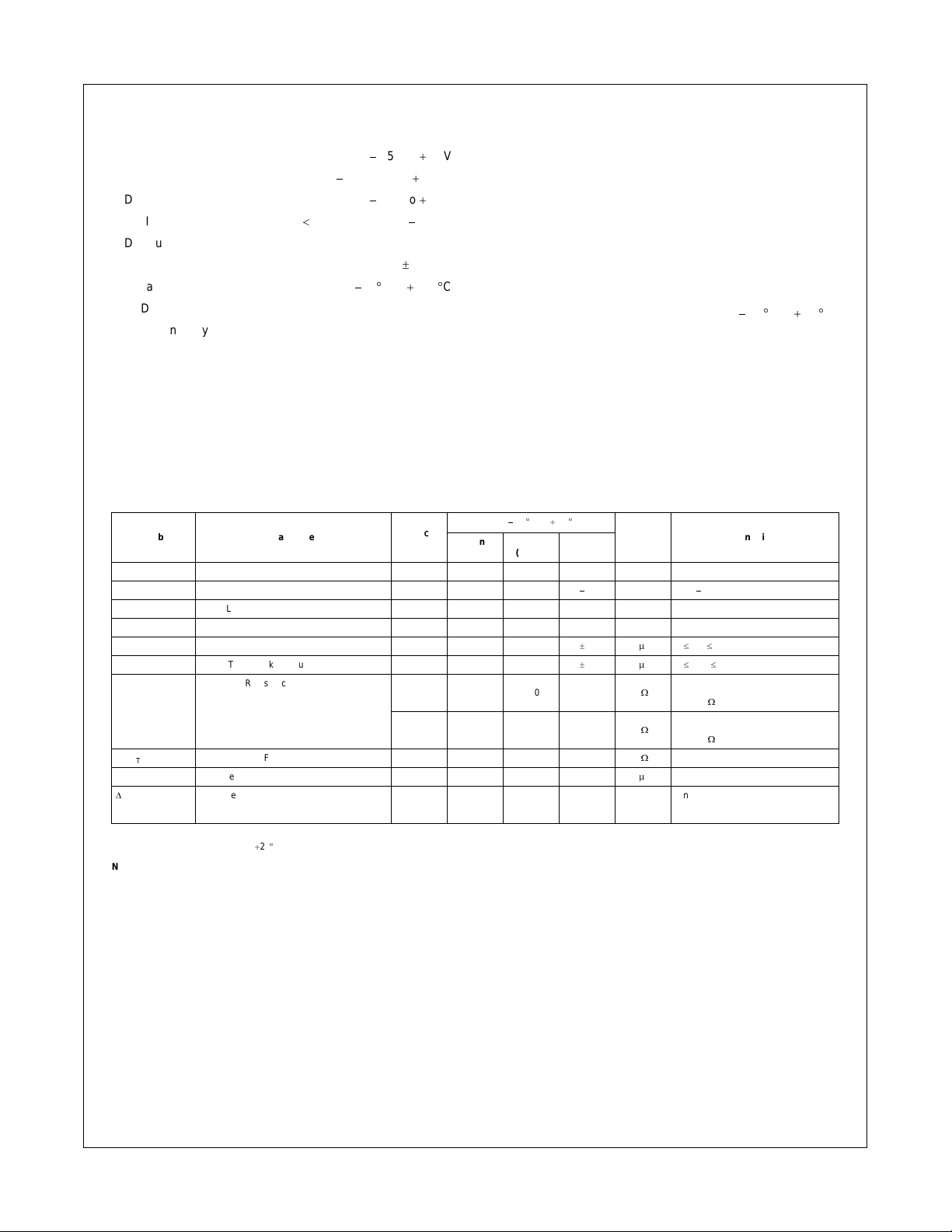
DC Electrical Characteristics
Symbol Parameter
Analog Signal Range 0 2.0 V
V
IK
V
IH
V
IL
I
I
I
OFF
R
ON
R
FLAT(ON)
I
CC
'
I
CC
Clamp Diode Voltage 3.0
HIGH Level Input Voltage 3.0 - 3.6 2.0 V
LOW Level Input Voltage 3.0 - 3.6 0.8 V
Input Leakage Current 3.6
OFF-STATE Leakage Current 3.6
Switch On Resistance
(Note 6) RI = 75 :, ION = 13 mA
On Resistance Flatness (Note 7) 3.0 1.0
Quiescent Supply Current 3.6 1.0
Increase in I
per Input 3.6 30.0 uA One Input at 3.0V
CC
Recommended Operating Conditions
(Note 4)
Power Supply Operating (VCC) 3.0V to 3.6V
Input Voltage (V
50 mA
r
100 mA
V
CC
(V)
3.0 5.0 7.0
3.0 4.5 6.0
Output Voltage (V
Input Rise and Fall Time (tr, tf)
Switch Control Input 0 ns/V to 5 ns/V
Switch I/O 0 ns/V to DC
Free Air Operating Temperature (T
Note 2: The Absolute Maximum Ratings are those values beyond which the safety of
the device cannot be guaranteed. The device should not be operated at these limits.
The parametric values defined in the Electrical Characteristics tables are not guaranteed at the absolute maximum rating. The Recommended Operating Conditions
tables will define the conditions for actual device operation.
Note 3: The input and output negative voltage ratings may be exceeded if the input
and output diode current ratings are observed.
Note 4: Unused control inputs must be held HIGH or LOW. They may not float.
TA = 40 qC to 85 qC
Min Typ
(Note 5)
)0V to V
IN
)0V to V
OUT
)
A
Max
1.2 V IIN = 18 mA
r
1.0
r
1.0
Units Conditions
P
A0 d VIN d 3.6V
P
A0 d A, B d V
VIN = 1.0V
:
VIN = 2.0V
:
RI = 75 :, ION = 26 mA
:
I
= 13 mA, VIN = 0 to V
OUT
P
AVIN = VCC or GND, I
Other Inputs at VCC or GND
40 qC to 85 qC
CC
OUT
CC
CC
CC
= 0
Note 5: Typical values are at TA = 25qC
Note 6: Measured by the voltage drop between A and B pins at the indicated current through the switch. On Resistance is determined by the lower of the voltages on the two
(A or B) pi ns.
Note 7: Flatness is defined as the difference between the maximum and minimum value On Resistance over the specified range of conditions.
3 www.fairchildsemi.com
Page 4
AC Electrical Characteristics
FSAV430
Symbol Parameter
t
ON
t
OFF
DG Differential Gain 3.0 to 3.6 0.2
DP Differential Phase 3.0 to 3.6 0.1
O
IRR
X
TALK
BW
Note 8: Typical values are at VCC = 3.3V and TA = 25qC
Turn ON Time S-to-Bus A 3.0 to 3.6 4.8 7.0
Output Enable Time OE-to-A 3.0 to 3.6 4.5 6.8
Turn OFF Time S-to-Bus A 3.0 to 3.6 2.2 4.0
Output Disable Time OE-to-A 3.0 to 3.6 2.2 4.0
Non-Adjacent OFF-Isolation 3.0 to 3.6
Non-Adjacent Channel Crosstalk 3.0 to 3.6
3dB Bandwidth 3.0 to 3.6 1.1 GHz RL = 50: (DQFN)
V
CC
(V)
3.0 to 3.6 800
3.0 to 3.6 650 R
3.0 to 3.6 600 RL = 75: (QSOP and TSSOP)
Capacitance
Symbol Parameter
C
IN
C
ON
C
OFF
Control Pin Input Capacitance 2.5 pF VCC = 0V
A/B ON Capacitance 12.0 pF VCC = 3.3V, OE = 0V
Port B OFF Capacitance 4.0 pF VCC and OE = 3.3V
T
= 40qC to 85qC
A
Min Typ
(Note )
T
= 40qC to 85qC
A
Typ (Note )
40.0
60.0
Max
Units Conditions
Bn = 2.0V
ns
ns Bn = 2.0V
RL = 75:, f= 3.58MHz Figures
%
R
= 75:, f= 3.58MHz Figures
Degree
Units Conditions
L
f = 30MHz, RL = 75
dB
RL = 75:, f= 30MHz Figures
dB
R
= 50: (QSOP and TSSOP)
L
MHz
= 75: (DQFN)
L
Figure
Number
Figures
8, 9
Figures
8, 9
2, 3
2, 3
:
Figures
4, 10
5, 11
Figures
1, 12
Note 9: Typical values are at VCC = 3.3V and TA = 25qC
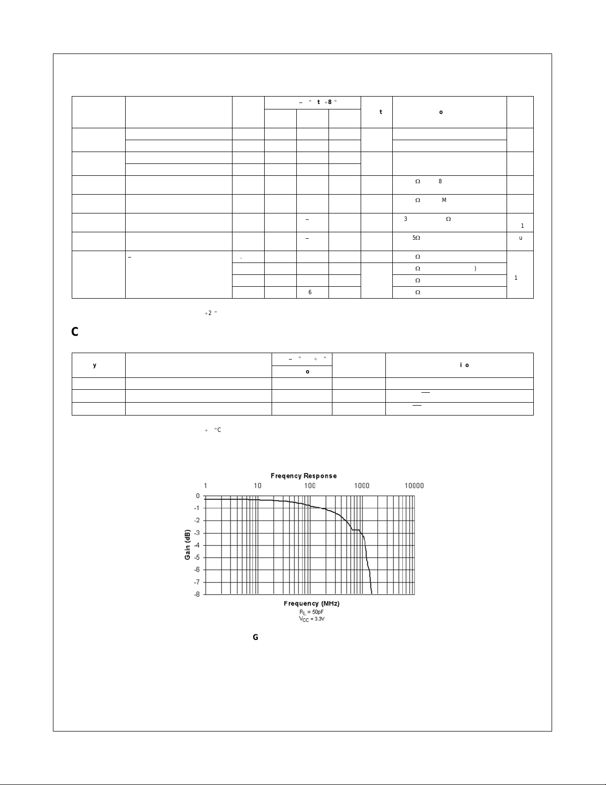
FIGURE 1. Gain vs. Freq u e nc y
www.fairchildsemi.com 4
Page 5
FSAV430
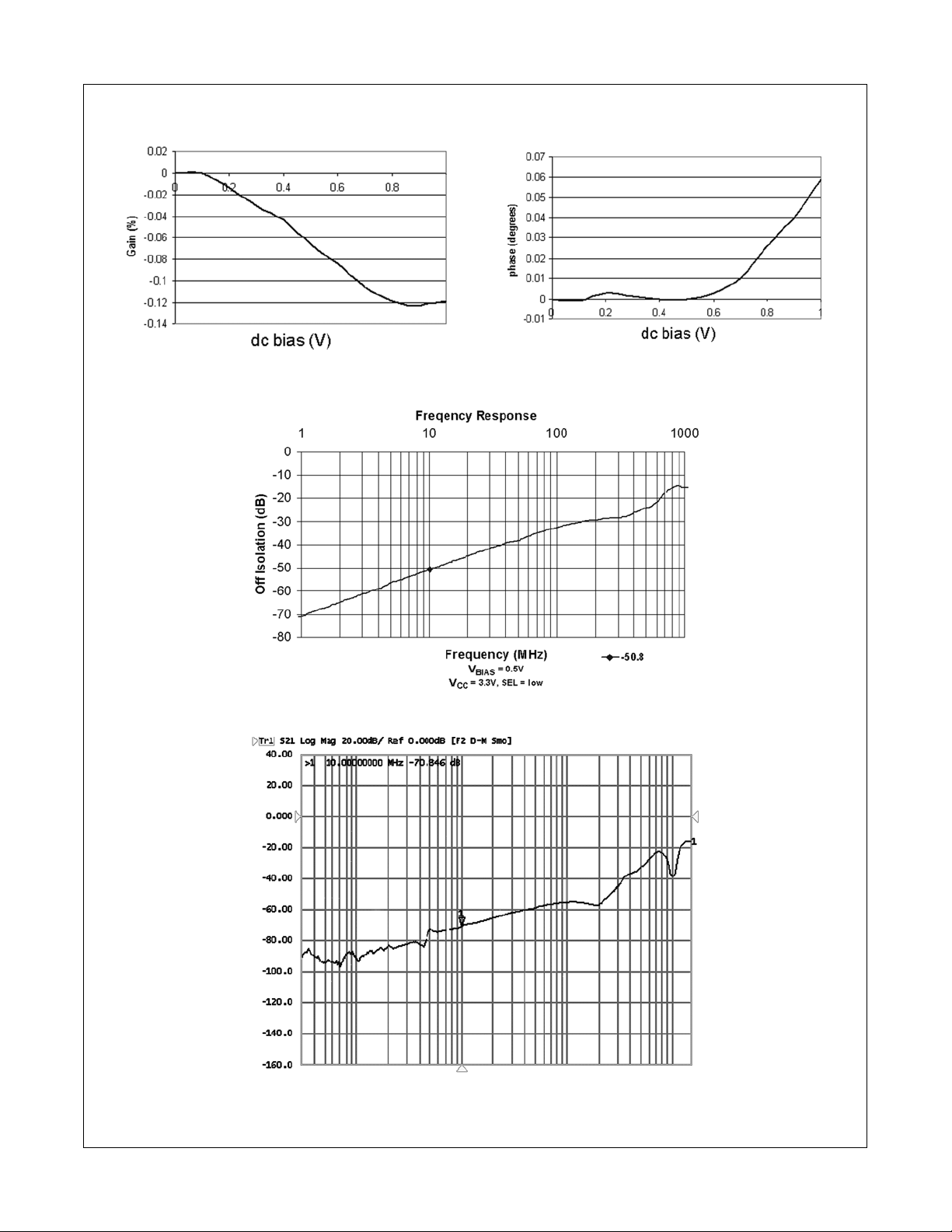
FIGURE 2. Differential Gain vs. dc bias
FIGURE 3. Differential Phase vs. dc bias
FIGURE 4. OFF Isolation
FIGURE 5. OFF Crosstalk vs. Frequency
5 www.fairchildsemi.com
Page 6
FSAV430
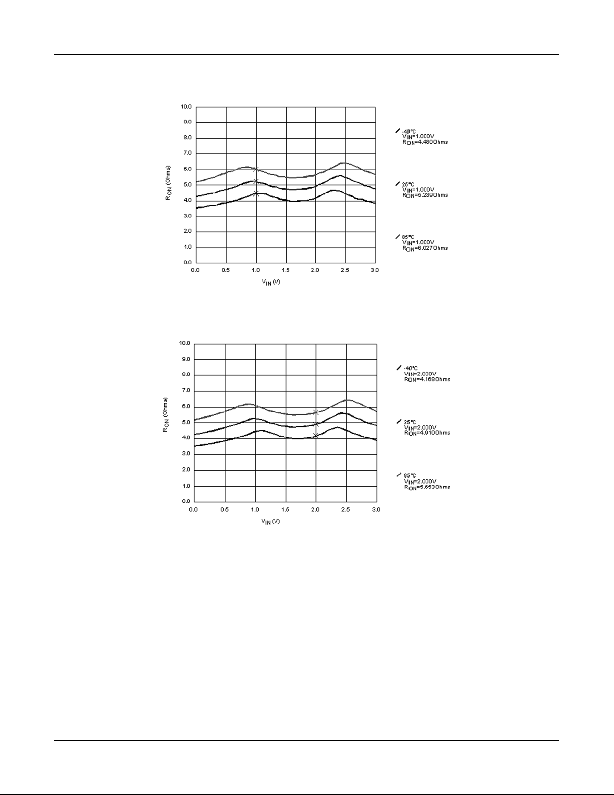
FIGURE 6. RON Switch On Resistance, ION = 13mA, VCC = 3.0V
FIGURE 7. R
www.fairchildsemi.com 6
Switch On Resistance, ION = 26mA, VCC = 3.0V
ON
Page 7
AC Loading and Waveforms
FSAV430
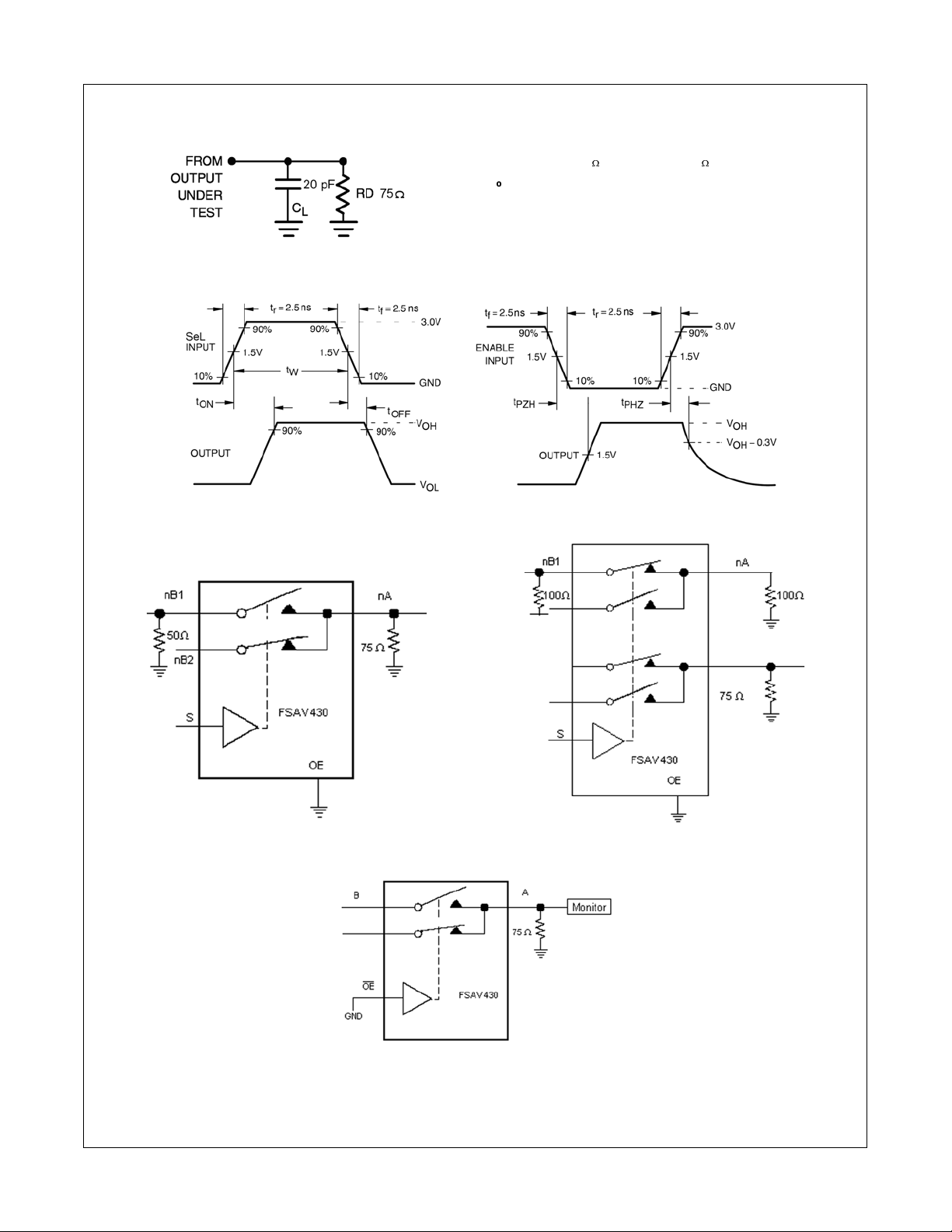
Note: Input driven by 50 : source terminated in 50
Note: C
includes load and stray capacitance
L
Note: Input PRR = 1.0 MHz, tW = 500 ns
FIGURE 8. AC Test Circuit
FIGURE 9. AC Waveforms
:
FIGURE 10. OFF Isolation Test
FIGURE 11. Crosstalk Test
FIGURE 12. Bandwidth Test
7 www.fairchildsemi.com
Page 8
Tape and Reel Specification
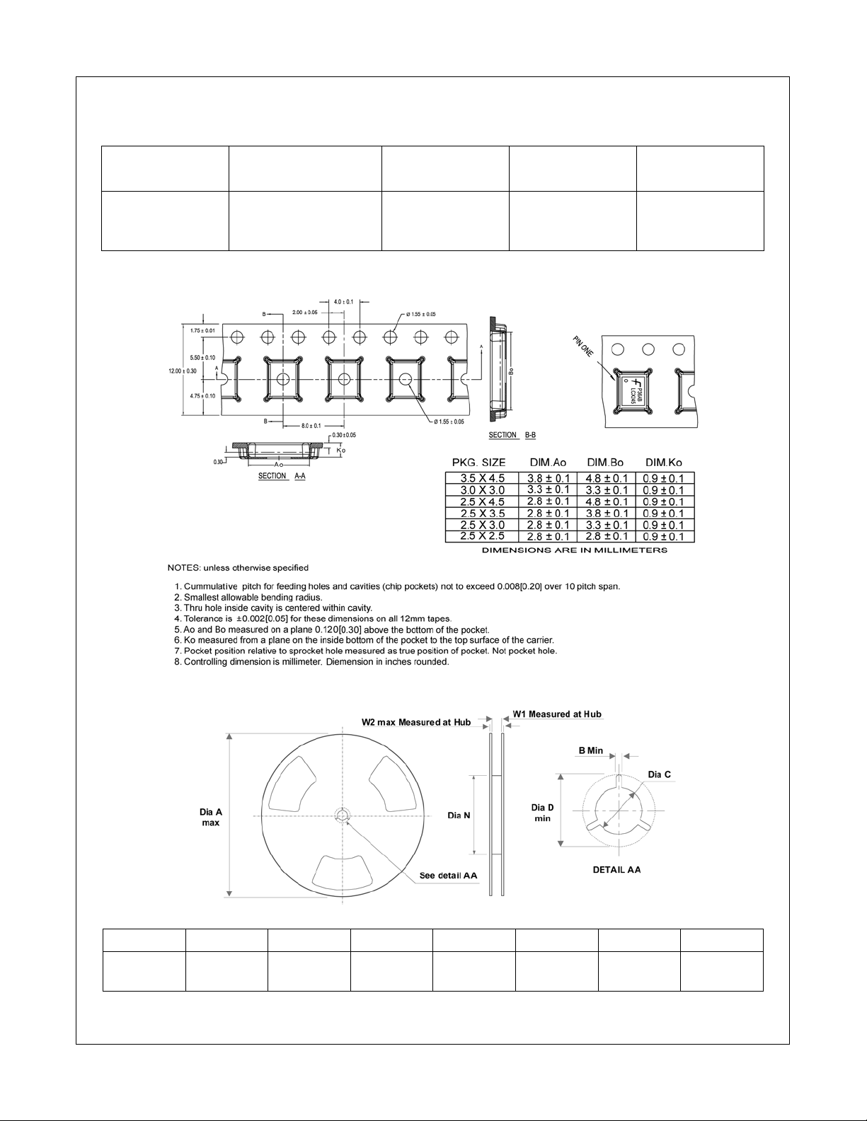
Tape Format for DQFN
FSAV430
Package Tape Number Cavity Cover Tape
Designator Section Cavities Status Status
BQX Carrier 2500/3000 Filled Sealed
TAPE DIMENSIONS inches (millimeters)
Leader (Start End) 125 (typ) Empty Sealed
Trailer (Hub End) 75 (typ) Empty Sealed
REEL DIMENSIONS inches (millimeters)
Tape SizeABCDNW1W2
12 mm
www.fairchildsemi.com 8
13.0 0.059 0.512 0.795 7.008 0.488 0.724
(330) (1.50) (13.00) (20.20) (178) (12.4) (18.4)
Page 9
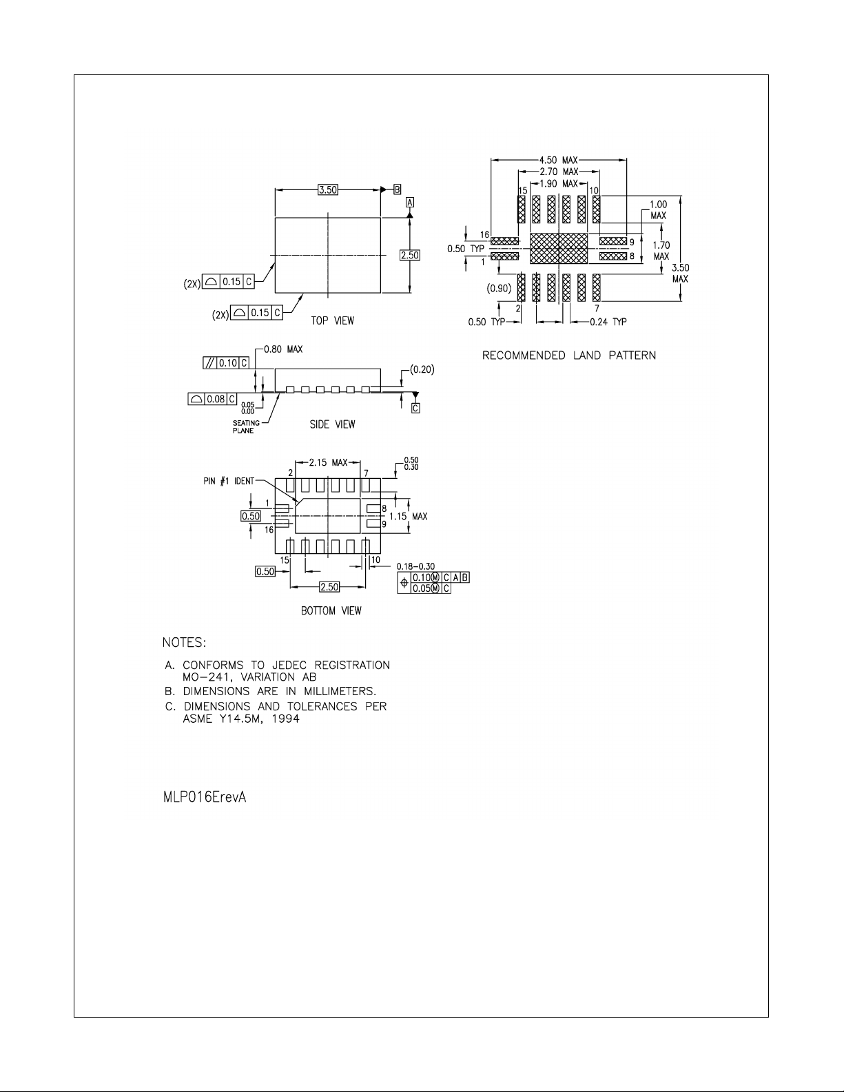
Physical Dimensions inches (millimeters) unless otherwise noted
FSAV430
Pb-Free 16-Terminal Depopulated Quad Very-Thin Flat Pack No Leads (DQFN), JEDEC MO-241, 2.5 x 3.5mm
Package Number MLP016E
9 www.fairchildsemi.com
Page 10
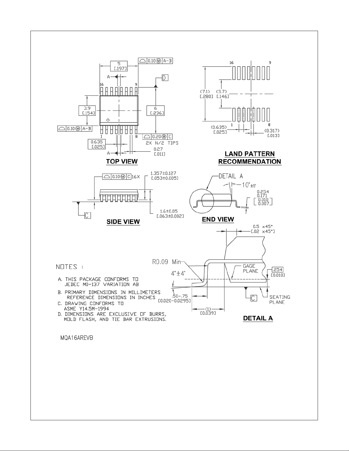
Physical Dimensions inches (millimeters) unless otherwise noted (Continued)
FSAV430
16-Lead Quarter Size Small Outline Package (QSOP), JEDEC MO-137, 0.150" Wide
Package Number MQA16A
www.fairchildsemi.com 10
Page 11
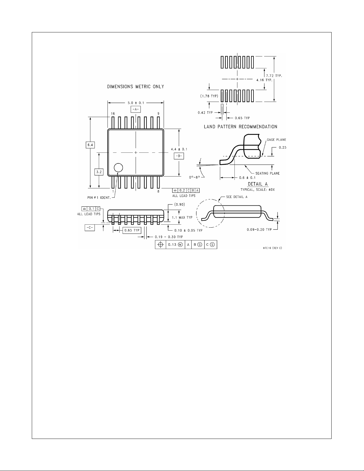
Physical Dimensions inches (millimeters) unless otherwise noted (Continued)
FSAV430
16-Lead Thin Shrink Small Outline Package (TSSOP), JEDEC MO-153, 4.4mm Wide
Package Number MTC16
Technology Description
The Fairchild Switch family derives from and embodies Fairchild’s proven switch technology used for several years in its 74LVX3L384
(FST3384) bus switch product.
11 www.fairchildsemi.com
Page 12
FSAV430 Low Voltage 1.1GHz 4 Channel 2:1 Video Switch
DISCLAIMER
FAIRCHILD SEMICONDUCTOR RESERVES THE RIGHT TO MAKE CHANGES WITHOUT FURTHER NOTICE TO ANY
PRODUCTS HEREIN TO IMPROVE RELIABILITY, FUNCTI ON OR DESIGN. FAIRCHILD DOES NOT ASSUME ANY LIABILITY
ARISING OUT OF THE APPLICATION OR USE OF ANY PRODUCT OR CIRCUIT DESCRIBED HEREIN; NEITHER DOES IT
CONVEY ANY LICENSE UNDER ITS PATENT RIGHTS, NOR THE RIGHTS OF OTHERS.
LIFE SUPPORT POLICY
FAIRCHILD’S PRODUCTS ARE NOT AUTHORIZED FOR USE AS CRITICAL COMPONENTS IN LIFE SUPPORT DEVICES
OR SYSTEMS WITHOUT THE EXPRESS WRITTEN APPROVAL OF FAIRCHILD SEMICONDUCTOR CORPORATION
As used herein:
1. Life support devices or systems are devices or systems
which, (a) are intended for surgical implant into the body, or
(b) support or sustain life, or (c) whose failure to perform
when properly used in accordance with instructions for use
provided in the labeling, can be reasonably expected to
result in significant injury to the user.
2. A critical component is any component of a life support
device or system whose failure to perform can be reasonably expected to cause the failure of the life support device
or system, or to affect its safety or effectiveness.
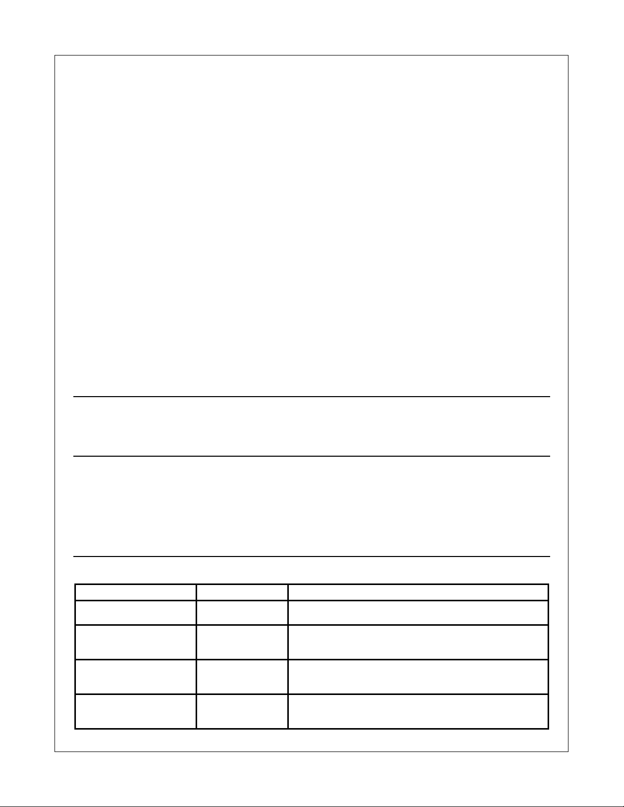
PRODUCT STATUS DEFINITIONS
Definition of terms
Datasheet Identification Product Status Definition
Advance Information Formative or In Design This datasheet contains the design specifications for product develop-
Preliminary First Production This datasheet contains preliminary data, and supplementary data will
No Identification Needed Full Production This datasheet contains final specifications. Fairchild Semiconductor
Obsolete Not In Production This datasheet contains specifications on a product that has been dis-
ment. Specifications may change in any manner without notice.
be published at a later date. Fairchild Semiconductor reserves the right
to make changes at any time without notice in order to improve design.
reserves the right to make changes at any time without notice in order
to improve design.
continued by Fairchild Semiconductor. The datasheet is printed for reference information only.
www.fairchildsemi.com 12
 Loading...