

Page 1

F
P
C
O
N
F
P
C
O
F
P
C
CONTENTS
■■ CCAAUUTTIIOONN FFOORR PPRROOPPEERR UUSSEE OOFF FFPPCCOONN
O
N
N
11--44
■■ RRUULLEE FFOORR PPRROOPPEERR
SERIES CHART …………………………………………………………….… 5
FREQUENCY COMPENSATION COEFFICIENT ……………….……….. 6
PART NUMBER ……………………………………….………………………. 6
DIMENSIONS …………..……………………………………………..………. 6
DETAILED TAPING SPECIFICATION ………………………………………. 7
LEAD FORMING & CUT…………….…………………………………………... 7
V -CHIP TYPE SPECIFICATIONS 8 - 9
■■ SSEERRIIEESS
SSEERRIIEESS
PSH
Ultra Low ESR, High ripple current, High reliability
Durability :1000 hours at 125℃ …………………………………………
FFEEAATTUURREESS
1100--1111
PSR
PSB
PVH
PVR
■■ TTEECCHHNNIICCAALL DDAATTAA ………………………………………………………………………………………………………………………………..
Ultra Low ESR<7mΩ, High ripple current, High reliability
Durability :2000 hours at 105℃ …………………………………………
Ultra Low ESR, High ripple current, High reliability
Standard , Durability :2000 hours at 105℃ ..…. ……………………
V -CHIP TYPE
Ultra Low ESR, High ripple current, High reliability
Durability :1000 hours at 125℃ …………………………………………
V -CHIP TYPE
Ultra Low ESR, High ripple current, High reliability,
Durability :2000 hours at 105℃ …………………………………………
1122--1133
1144--1155
1166--1177
1188--1199
2200--2211
Page 2
F
P
C
O
N
F
P
C
C
O
O
F
P
N
N
CAUTION FOR PROPER USE OF FP-CON
Upon using FP-CON, please pay attention to the points listed below.
When the following types of electrical loads applied to FP-CON of electrical property occurs:
z reverse voltage
z voltage exceeds rated working voltage
z allowable ripple current is exceeded
z severe charging / discharging
1、CAUTION DURING CIRCUIT DESIGN
1.1 PROHIBITED CIRCUITS
Leakage current may increase, capacitance may also fluctuate after soldering. Therefore, FP-CON cannot
be used on the following circuits.
z High impedance voltage retention circuits.
z Coupling circuits
z Time constant circuits
1.2 OPERATIONAL ENVIRONMENT, MOUNTINGENVIRONMENT AND CONDITIONS.
z Ensure that operational and mounting conditions low the specified conditions detailed in the catalog
specification sheets.
1.3 OPERATING TEMPERATURE, RIPPLE CURRENT AND LOAD LIFE.
1.3.1 Operating temperature and applied ripple current should be within the specified value in the catalog
or specification sheets.
z Do not use FP-CON at temperature which exceeds the specified operating temperature range.
z Do not apply excessive current to the FP-CON, which exceeds the specified maximum permissible
ripple current.
1.3.2
During circuit design, please ensure that FP-CON are selected to match with the lifetime
requirements of the application.
1.4 APPLICATION
z FP-CON are normally polarized. Reverse voltage or AC voltage should not be applied. When polarity
applied voltage is uncertain or when the polarity may flip over, non-polar type FP-CON should be used, but
of
the non-polar type cannot be used for AC circuit.
z Standard FP-CON are net suitable for rapid charge and discharge applications. Consult with Cushy
about specially designed FP-CON for rapid charge and discharge.
1.5 APPLIED VOLTAGE
z Do not exceed the rated voltage of FP-CON
z The combined value of D.C. voltage and the peak A.C. voltage shall not exceed the rated voltage
and shall not be reverse voltage.
z When DC voltage is low, negative ripple voltage peak value must not become a reverse voltage that
exceeds.
z Use the within 20 % of the rated voltage for applications which may cause the reverse voltage during
the transient phenomena when the power is turned off or the source is switched.
1.6 INSULATION
The PVC sleeve of FP-CON is not recognized as an insulator, and therefore, the standard FP-CON
should not be used in a place where insulation function is needed. Please consult with Cushy should you
require a higher grade of insulating sleeve.
1.7 CONDITIONS OF USE
The following environment should be avoided when using FP-CON.
z Damp conditions such as water, saltwater spray, or oil spray or fumes. High humidity or humidity
condensation situations.
z Hazardous gas/fumes such as hydrogen sulfide, sulfurous acid gas, nitrous acid, chlorine gas or
ammonia.
z Exposure to ozone, ultraviolet rays or radiation.
1.8 CONSIDERATION TO ASSEMBLY CONDITION.
Design the appropriate hole spacing to match the lead pitch of FP-CON.
1
Page 3
F
P
C
O
N
F
P
C
O
F
P
C
O
N
N
CAUTION FOR PROPER USE OF FP-CON
1.9 CONSIDERATION TO CIRCUIT DESIGN
z Any copper lines or circuit patterns should not be laid under the FP-CON.
z Parts which radiate heat should not be placed close to or reverse side of the FP-CON on the PCB
board.
1.10 THERS
z Performance of electrical characteristics of FP-CON are affected by variation of operating temperature
frequency. Consider this variation when designing the circuit.
and
z Excessive holes and connection hole between both sides on the PW board should be avoided around or
under the mounting area of the FP-CON on double sided or multiplayer PW board.
z Consider current balance when 2 or more FP-CON are connected in parallel.
z Use bleeder resistors when 2 or more FP-CON are connected in series. In this case, the resistors should
be connected parallel to the FP-CON.
2、CAUTION FOR ASSEMBLING FP-CON
2.1 CAUTION BEFORE ASSEMBLY
2.1.1 Polarity Marking of FP-CON
Please confirm the polarity to avoid applying any reverse voltage or AC voltage to the FP-CON.
Polarity is indicated as below:
z Negative polarity is indicated on the side of body by means of a stripe or an arrow.
z On radial leadedFP-CON, the shorter lead is the negative terminal.
z On Surface Mount FP-CON, the mark ﹝﹞indicates the direction of Negative Polarity.
2.1.2 Voltage Treatment
The following voltage treatment should be done on the FP-CON that have been stored for a long
time.
z Voltage Treatment
Leakage current may increase when FP-CON are stored for a long period of time. In this case, apply
rated voltage for 1 hour at 60 to 70 ℃ with load of 1 kΩ resistor, and then discharged through a
resistor of about lΩ/Volt.
z FP-CON cannot be recycled after mounting and applying electricity in unit. The FP-CON which are
removed from PW board for the purpose of measuring electrical characteristics at the periodical
inspection should only be recycled for the same position.
z FP-CON may accumulate charge naturally during storage. In this case, discharge through a 1kΩ
resistor before use.
z Leakage current of FP-CON may be increased during long storage time. In this case, the FP-CON
should be subject to voltage treatment through a l kΩ resistor before use.
2.2 IN THE ASSEMBLY PROCESS - 1
z Ensure rated voltage and nominal capacitance of the FP-CON before mounting.
z Ensure the FP-CON polarity before mounting.
z Do not use a FP-CON which has been dropped onto a hard surface.
z Do not use FP-CON with damaged or dented cases or seals.
2.3 IN THE ASSEMBLY PROCESS - 2
z FP-CON should be mounted after confirmation that hole spacing on PCB board matches the lead pitch
of the FP-CON.
z Avoid excessive force when clinching lead wire during auto-insertion process.
z Avoid excessive shock to FP-CON by automatic insertion machine, during mounting, parts inspection
or centering operations.
2.4 SOLDERING
z Soldering conditions (temperatures, times) should be within the specifi ed conditions which are
described in the catalog or specification sheets.
z In case lead wire reforming is needed due to inappropriate pitch between FP-CON and holes on PCB
board, stress to the FP-CON should be avoided.
z In case soldered capacitor has to be withdrawn from the PCB board by soldering irons, the FP-CON
should be removed after solder has melted sufficiently in order to avoid stress to the FP-CON or lead
wires.
z Soldering iron should never touch the FP-CON body.
2
Page 4
F
P
C
O
N
F
P
C
C
O
O
F
P
N
N
CAUTION FOR PROPER USE OF FP-CON
2.5 FLOW SOLDERING
z Do not dip FP-CON body into melted solder.
z Soldering condition (preheat, soldering temperature, dipping time) should be within the specified
standard which is described in the catalog or specification sheets.
z Other devices which are mounted near FP-CON should not touch the FP-CON.
2.6 REFLOW SOLDERING
z Reflow soldering conditions (preheat, soldering temperature, reflow time) should follow the specified
standard which are described in the catalog or specification sheets.
z Heating standard should depend on surface of the FP-CON color or materials when infrared rays is used
because the
z Standard FP-CON cannot with stand two or more reflow processes. Consult with Cushy when two or
more reflow processes are needed.
2.7 HANDLING AFTER SOLDERING
z Do not bend or twist the FP-CON body after soldering on PCB board.
z Do not pick-up or move PCB board by holding the soldered FP-CON.
z Do not hit the FP-CON and isolate FP-CON from the PCB board or other device when stacking PCB
boards in store.
3、 OARD CLEANING
3.1 The use of ozone depleting cleaning agents are not recommended in the interest of protecting the
environment.
3.2 PCB board can be immersed or ultrasonically cleaned using suitable cleaning solvents for up to 5 minutes
(5L and 7L is up to 3 minutes) and up to 60℃ maximum temperatures.
3.3 Avoid using the following splvent groups unless specifically allowed for in the specification:
z Alkali solvents: could attack and dissolve the aluminum case.
z Petroleum based solvents: deterioration of the rubber seal could result.
z Xylene: deterioration of the rubber seal could result.
z Acetone: removal of the ink markings on the vinyl sleeve could result.
3.4 A thorough drying after cleaning is required to remove residual cleaning solvents which may be trapped
between the FP-CON and the circuit board. Avoid drying temperatures which exceed the maximum rated
temperature of the FP-CON.
3.5 Monitor the contamination levels of the cleaning solvents during use by electrical conductivity, pH, specific
gravity, or water content. Chlorine levels can rise with contamination and adversely affect the performance
of the FP-CON.
3.6 Electrolyte and Separator paper are Flammable.
Electrolyte and separator paper used in FP-CON are flammable. Also, Electrolyte is electrically conductive.
Therefore, in case Electrolyte gets contact with PC board, it may cause corrosion of circuit pattern, or
tracking or short circuit between patterns, and may lead to smoke generation or ignition at the worst cases.
Please make considerations to the above risk in designing circuit patterns and determining the mounting
method and mounting location of FP-CON
3.7 ADHESIVES AND COATING MATERIALS
z Do not use halogenated adhesives and coating materials to fix FP-CON.
z Solvents should be dried up before using adhesives or coating materials. Do not cover up all the
sealing area of FP-CON with adhesives or coating materi als, make coverage only partial.
FP-CON heat absorption depends on the surface color or materials. Check heat condition.
4、 CAUTION DURING USE Of FP-CON IN SETS
z Do not touch the terminals of FP-CON.
z Do not connect electrical terminals of the FP-CON. Keep the FP-CON free from conductive solution,
such as acid, alkali and so on.
z Ensure the operational environment of the equipment in which the FP-CON has been built is within the
specified condition mentioned in the catalog or specification sheets.
3
Page 5
F
P
C
O
N
F
P
C
O
F
P
C
O
N
N
CAUTION FOR PROPER USE OF FP-CON
5、 EMERGENCY ACTION
z If a short circuit occurs and odorous gas is released, either turn off the main power of the equipment
or unplug the power cord from the outlet.
z Do not stand close to the capacitors. In case of eye contact, flush the open eye with large amount of
clean water immediately. In case of ingestion, gargle with water immediately, do not swallow.
z Do not touch electrolyte but wash skin with soap and water in case of skin contact.
6、 STORAGE CONDITION
z FP-CON should not be stored in high temperatures or where there is a high level of humidity. The
suitable storage condition is 5℃-35℃ and less than 75% in relative humidity.
ITEM Before unseal After unseal
Taping product
(SMD)
Bag packing product
(radial type)
Radial taping product
z FP-CON should not be stored in damp conditions such as water, saltwater spray or oil spray.
z Do not store FP-CON in an environment full of hazardous gas (hydrogen sulfide, sulfurous acid gas,
nitrous acid, chlorine gas or ammonia).
z FP-CON should not be stored under exposure to ozone, ultraviolet rays or radiation.
Within 6 months after
delivery
(Unopened condition)
Within 1 year after delivery
(Unopened condition)
Within 6 months after
delivery
(Unopened condition
Within 30 days from opening
(Packaged condition with carrier
tape)
Within 7 days from opening
(1 week)
Within 7 days from opening
(1 week)
7、 DISPOSAL
z FP-CON comprises solid organic compounds, various metals, resin, rubber, etc. Treat it as industrial
waste when disposing of it. In case of disposing a large amount of FP-CON, CUSHY can dispose on
behalf.
For further details
Please refer to: EIAJ RCR-2367 (Technical report published Electronic
Industries Association of Japan in march 1995).
4
Page 6
F
P
C
O
N
F
P
C
P
C
O
O
F
N
N
RULE FOR PROPER USE
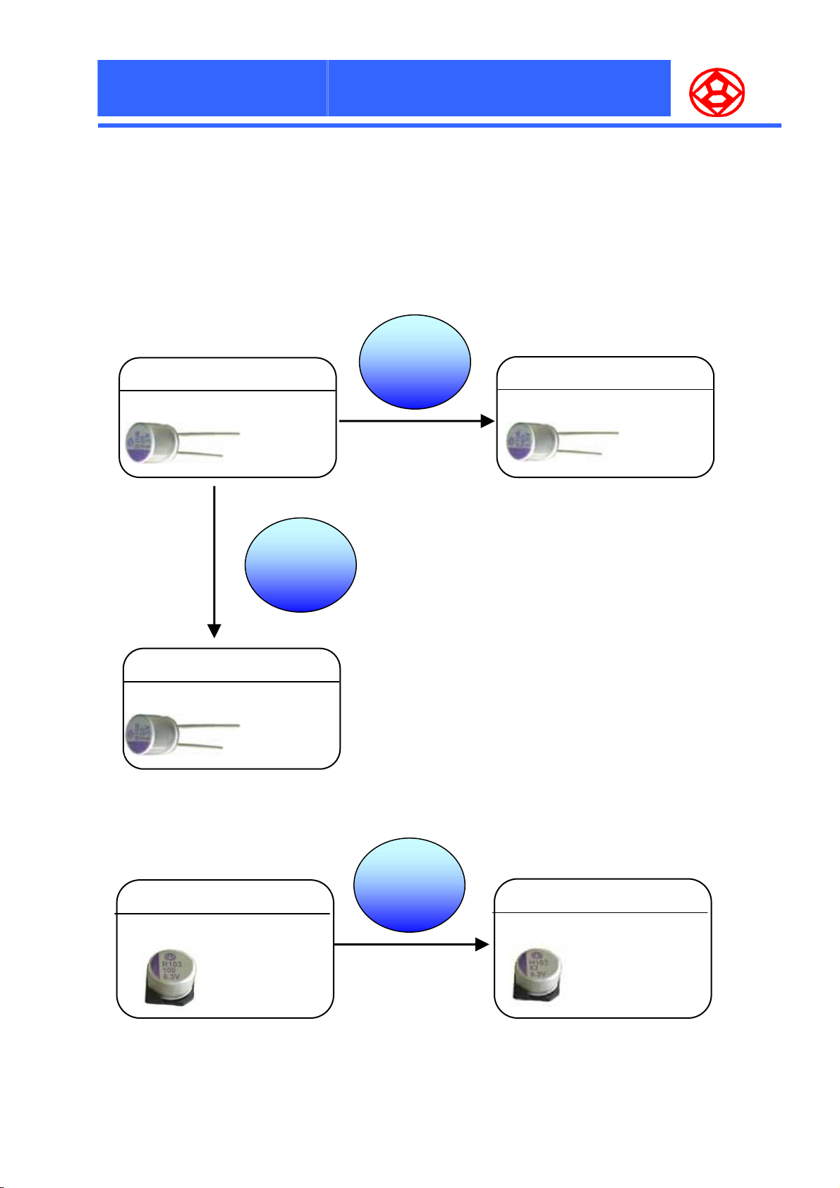
■ SERIES CHART
1、Standard Radial
PSB
Standard
105℃
2000Hrs
High
Reliability
Low
Impedance
PSR
Low Impedance
105℃
< 7 mΩ
High Reliability
2、V-Chip Type
Standard
PSH
PVR
105℃
125℃
1000Hrs
2000Hrs
High
Reliability
PVH
High Reliability
125℃
1000Hrs
5
Page 7
R
F
P
C
O
N
F
P
C
O
F
P
C
O
N
N
RULE FOR PROPER USE
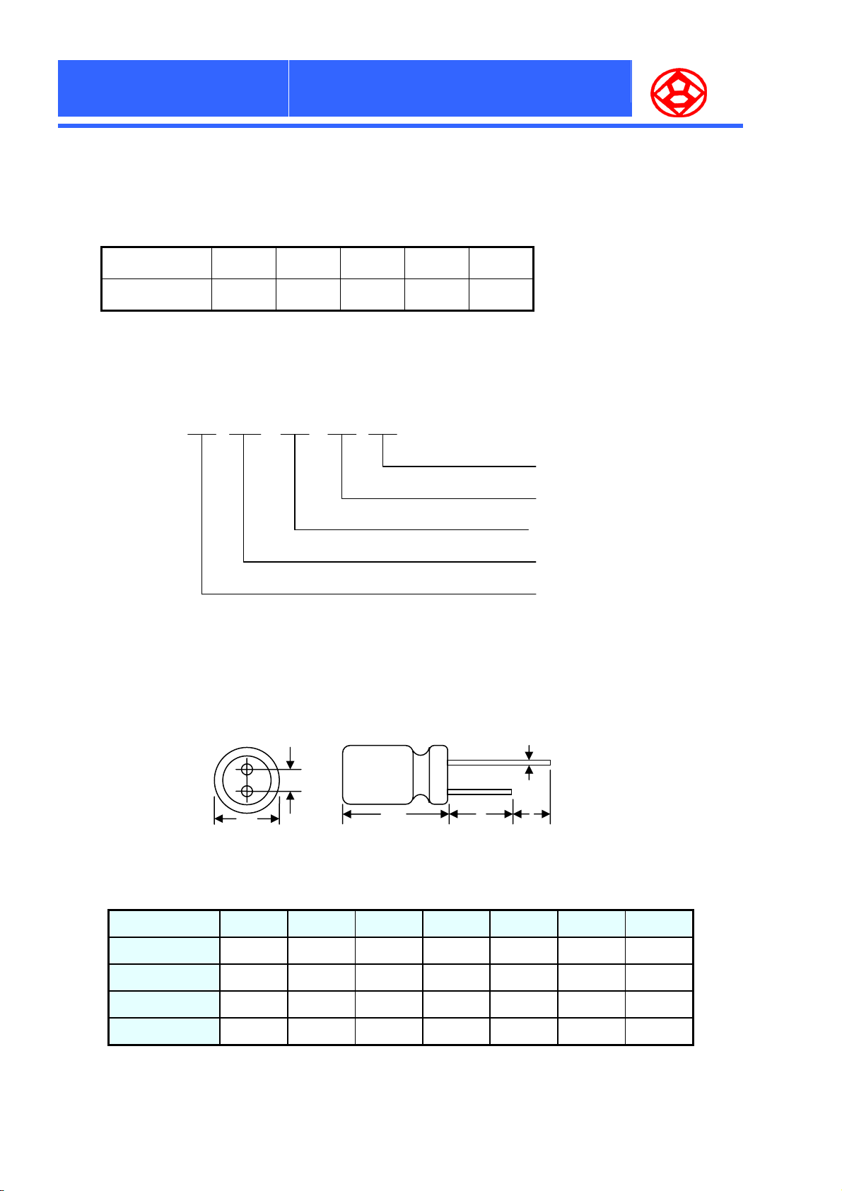
■ FREQUENCY COMPENSATION COEFFICIENT
Frequency 120 1K 10K 100K 300K
■ PART NUMBERING SYSTEM
Coefficient 0.05 0.30 0.50 1.00 1.00
2 PS
5 M 0808
Case code
Cap tolerance(±20%)
Nominal cap code
Series name
■ DIMENSIONS (mm)
φD+0.5 MAX
Case code 0605 0607
ψD
L 5.2 7.6
6.3 6.3
Rated voltage in volt
F
L+1.5 MAX
0808
8
8
15MIN
0809 0812 1010 1012
8 8 10 10
9 12 10 12
ψd
4MIN
F 2.5 2.5
ψd
0.45 0.45
3.5
0.6
3.5 3.5 5.0 5.0
0.6 0.6 0.6 0.6
6
Page 8
F
P
C
O
N
F
P
C
P
C
O
O
F
N
N
RULE FOR PROPER USE
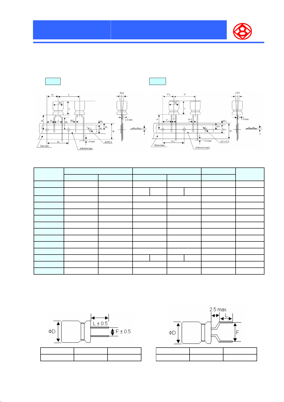
■ DETAILED TAPING SPECIFICATIONS
Fig.1 Formed Lead — (Code T ) Fig. 2 Straight Lead — (Code TS)
CODE
ψd
L 7.0
P 12.7
P0 12.7
P1 3.85
P2 6.35
F 5.0
W 18.0
W0 6.0
W1 9.0
W2 1.5
H 17.5
H0 16.0
t
Fig. 1 Fig. 2 Fig. 1 Fig. 2 Fig. 2
0.45 0.45 0.6 0.6 0.6 ±0.05
0.7 0.7 0.7 0.7 0.7 ±0.3
6.3ψ 8ψ 10ψ
7.0
12.7
12.7
5.1
6.35
2.5
18.0
6.0
9.0
1.5
17.5
-
≦10
17.5 20.0
﹥10
12.7
12.7
3.85
6.35
5.0
18.0
10.0
9.0
1.5
16.0
≦10
17.5 18.5
﹥10
12.7
12.7
4.6
6.35
3.5
18.0
10.0
9.0
1.5
-
Dimensions in (mm)
21 Max.
12.7 ±1.0
12.7 ±0.3
3.85 ±0.7
6.35 ±1.3
5.0 ±0.5
18.0 ±0.5
11.5 Min.
9.0 +0.75 –0.5
1.5 Max.
18.5 ±0.75
- ±0.5
Tolerance
■ LEAD FORMING & CUT (mm)
1、Straight Cut — (Code C)
ψD
6.3ψ~10ψ L ± 0.5 F ± 0.5
L F
2、Forming & Cut —(Code CF)
ψD
7
≦ 8 ψ 5.0 ± 0.5 5.0 ± 0.5
L F
Page 9
F
P
C
O
N
F
P
C
O
F
P
C
O
N
N
RULE FOR PROPER USE
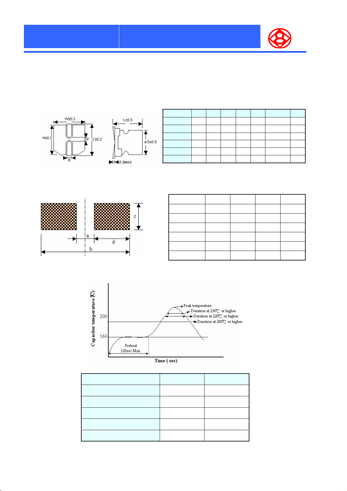
■ V-CHIP TYPE SPECIFICATIONS
1、DIMENSIONS (mm)
2、RECOMMENDED LAND PATTERN DIMENSION OF PWB
Case Code
0605 6.3 5.7 6.6 6.6 7.2 0.5~0.8 1.9
0607 6.3 7.7 6.6 6.6 7.2 0.5~0.8 1.9
0808 8 8.0 8.3 8.3 9.0 0.7~1.1 3.1
0812 8 12 8.3 8.3 9.0 0.7~1.1 3.1
1010 10 10 10.3 10.3 11 0.7~1.1 4.5
1012 10 12 10.3 10.3 11 0.7~1.1 4.5
Size Code a b c d
ψD
0605 2.1 9.1 1.6 3.5
0607 2.1 9.1 1.6 3.5
0808 2.8 11.1 1.9 4.1
0812 2.8 11.1 1.9 4.1
1010 4.3 13.1 1.9 4.3
1012 4.3 13.1 1.9 4.3
L W H C R P
3、REFLOW SOLDERING CONDIION
Item 1 2
Peak temperature
200℃ over time (max.)
220℃ over time (max.)
230℃ over time (max.)
Reflow number twice or less Only 1 time
250
℃ 260℃
60 sec. 60 sec.
50 sec. 50 sec.
40 sec. 40 sec.
★All temperature are measured on the topside of the Al-can and terminal surface.
8
Page 10
F
P
C
O
N
F
P
C
P
C
O
O
F
N
N
RULE FOR PROPER USE
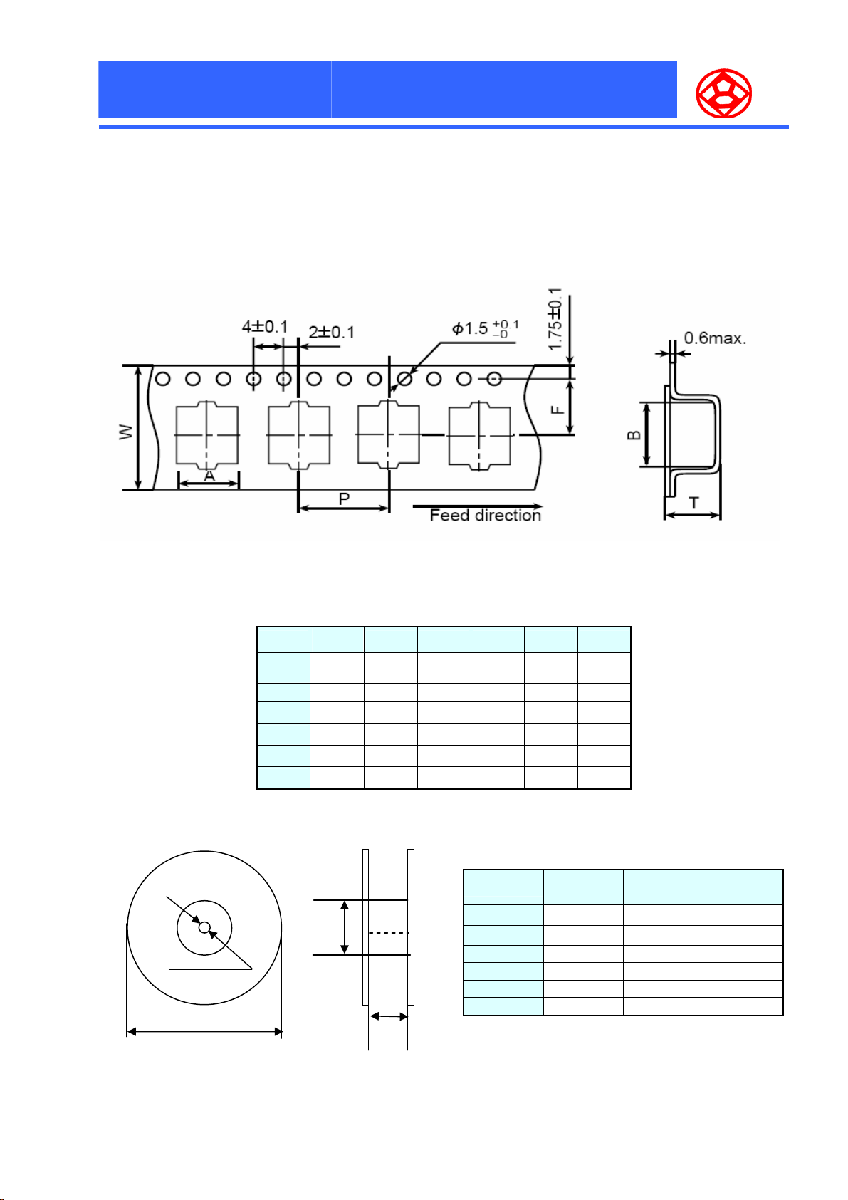
4、TAPING DIMENSIONS
DØ×L
0605 16.0 7.0 12 7.5 7.0 6.3
0607 16.0 7.0 12 7.5 7.0 8.2
0809 24.0 8.7 16.0 11.5 8.7 10.0
1010 24.0 10.7 16.0 11.5 10.7 11.0
0812 24.0 8.7 16.0 11.5 8.7 13.0
1012 24.0 10.7 16.0 11.5 10.7 13.0
5、REEL DIMENSIONS (mm)
ψ50Min
13±0.5
ψ382max
W±0.3
A±0.2 P±0.1 F±0.1 B±0.2 T±0.2
6、QUANTITY PER REEL/BOX
Size code
0605 1000 5000 18
0607 800 4000 18
0809 800 4000 26
0812 400 2000 26
1010 500 2500 26
1012 400 2000 26
W1
Quantity
(pcs/reel)
Quantity
(pcs/box)
W1
( mm)
9
Page 11
F
P
C
F
P
F
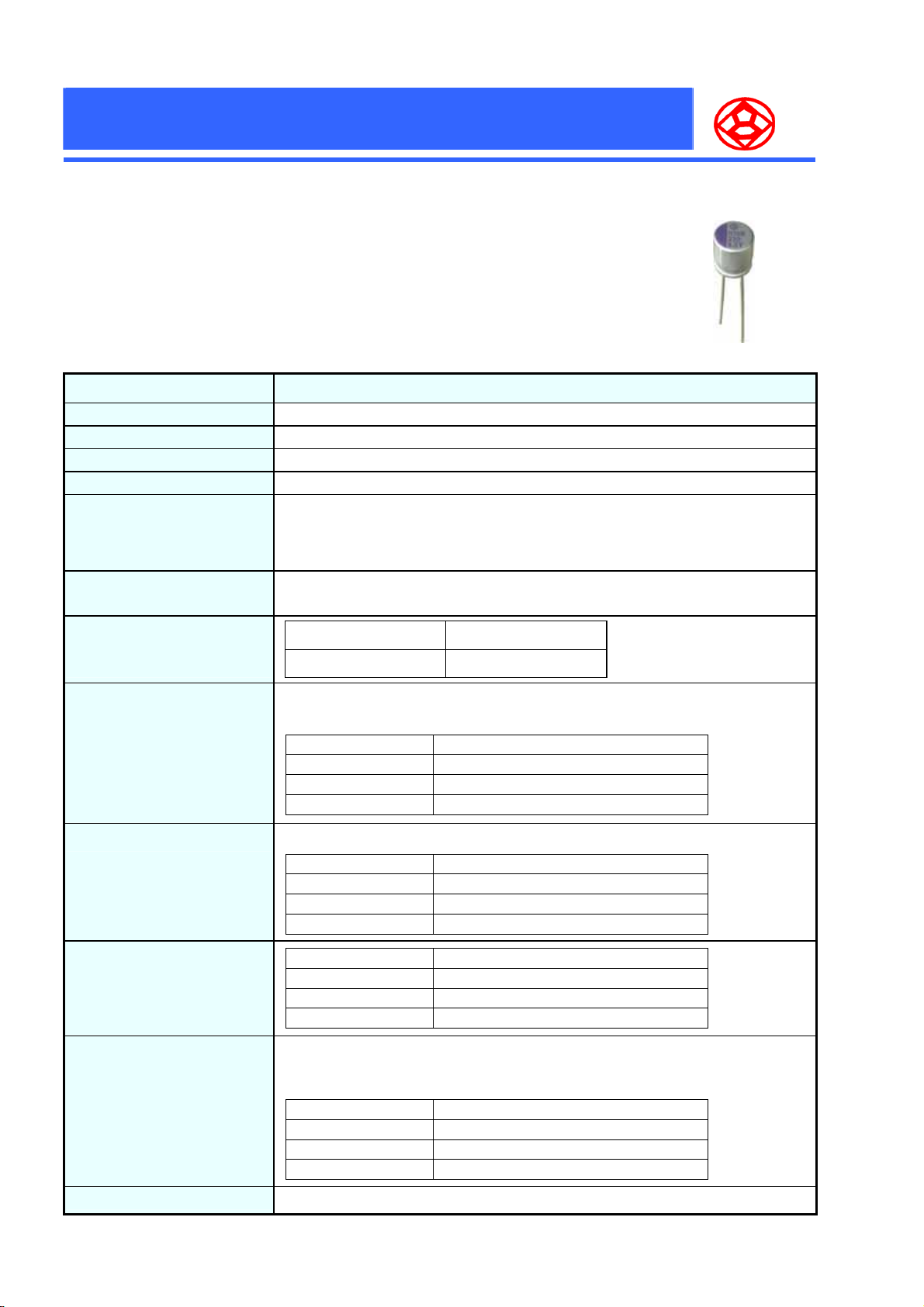
● Ultra Low ESR, High ripple current, High reliability, long life
● Rated voltage range : 2.5 to 16 Vdc
● 1000 hours at 125℃
● Suitable for DC – DC converters, voltage regulators and decouping applications
for computer motherboards
■ SPECIFICATIONS
Operating Temperature Range -55 ~ +125℃
Capacitance Tolerance ± 20 % (20℃、120Hz)
Dissipation Factor (tanδ) 0.12 (max.) (20℃、120Hz)
Surge Voltage Rated voltage × 1.15V
Leakage Current
O
C
O
P
C
O
P
S
H
P
S
P
S
Items Characteristics
H
H
N
N
N
S
e
r
i
e
s
S
e
r
i
e
s
S
e
r
i
e
s
I = 0.2CV . After 2 minutes application of rated voltage. ≦6.3ψ I = 0.5CV
I= Leakage Current (μA) C= Nominal Capacitance (μF) V= Rated Voltage
(If the leakage current is not stabilized,apply rated voltage for 120 minutes at 105℃)
Equivalent series resistance
( ESR )
High temperature
& Low temperature
Characteristic
Durability
High temperature & high
humidity
(Constant)
Resistance to Soldering heat
Flow method (260±5°C × 10s)
Please see the attached standard products list.
Z(-55℃)/Z(20℃) 0.75 ~ 1.25
Z(+125℃)/Z(20℃) 0.75 ~ 1.25
After applying the rate voltage for 1000 hours at 125℃ and then being stabilized at 20℃,
capacitors shall meet the following limits.
Capacitance Change Within ±20% of the initial value.
Dissipation Factor Not more than 150% of the specified value.
ESR Not more than 150% of the specified value.
Leakage Current Not more than the specified value.
After storing for 1000 hours at 60℃、90~95%R.H.
Capacitance Change Within ±20% of the initial value.
Dissipation Factor Not more than 150% of the specified value.
ESR Not more than 150% of the specified value.
Leakage Current Not more than the specified value.
Capacitance Change Within ±5% of the initial value.
Dissipation Factor Not more than the specified value.
ESR Not more than the specified value.
Leakage Current Not more than the specified value.
(100KHZ)
(20℃)
Surge Voltage Test
Failure Rate
The capacitors shall be subjected to 1000 cycles each consisting of charge with the surge
voltage specified at 105℃ for 30 seconds through a protective resistor(R=1kΩ) and discharge
for 5 minutes 30 seconds.
Capacitance Change Within ±20% of the initial value.
Dissipation Factor Not more than 150% of the specified value.
ESR Not more than 150% of the specified value.
Leakage Current Not more than the specified value.
1% per 1000 hours maximum (Confidence level 60% at 105℃)
10
Page 12
F
P
C
P
P
P
P
Size
Code
0605
0809
1010
0812
1012
C
C
S
S
S
O
O
O
H
F
P
F
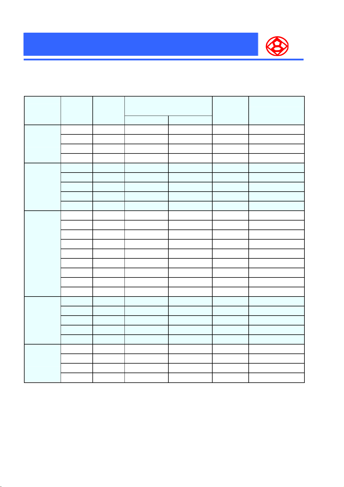
■ STANDARD PRODUCTS
H
H
N
N
N
S
e
r
i
e
s
S
e
r
i
e
s
S
e
r
i
e
s
Rated
voltage
V. D C (µF) 105℃<To 125≦℃ To 105≦℃ 20 , 100KHz℃
16 39 520 1620 50 16PSH390M0605
10 56 540 1700 45 10PSH560M0605
6.3 82 540 1700 45 6PSH820M0605
4 150 580 1800 40 4PSH151M0605
16 82 680 2200 40 16PSH820M0809
10 120 820 2600 35 10PSH121M0809
6.3 150 820 2600 35 6PSH151M0809
6.3 220 820 2600 35 6PSH221M0809
4 330 820 2600 35 4PSH330M0809
16 150 960 3100 30 16PSH151M1010
16 220 960 3100 30 16PSH221M1010
10 270 1180 3800 25 10PSH271M1010
10 330 1180 3800 25 10PSH331M1010
6.3 330 1180 3800 25 6PSH331M1010
6.3 470 1180 3800 25 6PSH471M1010
4 470 1180 3800 25 4PSH471M1010
4 560 1180 3800 25 4PSH561M1010
4 680 1180 3800 25 4PSH681M1010
16 180 1160 3700 20 16PSH181M0812
16 220 1160 3700 20 16PSH221M0812
10 330 1270 4000 17 10PSH331M0812
6.3 470 1350 4300 15 6PSH471M0812
4 560 1450 4600 13 4PSH561M0812
16 330 1500 4800 16 16PSH331M1012
10 560 1670 5300 13 10PSH561M1012
6.3 820 1740 5500 12 6PSH821M1012
4 1200 1740 5500 12 4PSH122M1012
Nominal
capacitance
Max. permissible ripple current
(mA r.m.s)
(-55 to 105℃、100KHz to 300KHz)
ESR
(mΩ) Max.
Part No.
11
Page 13
F
P
C
F
F
P
P
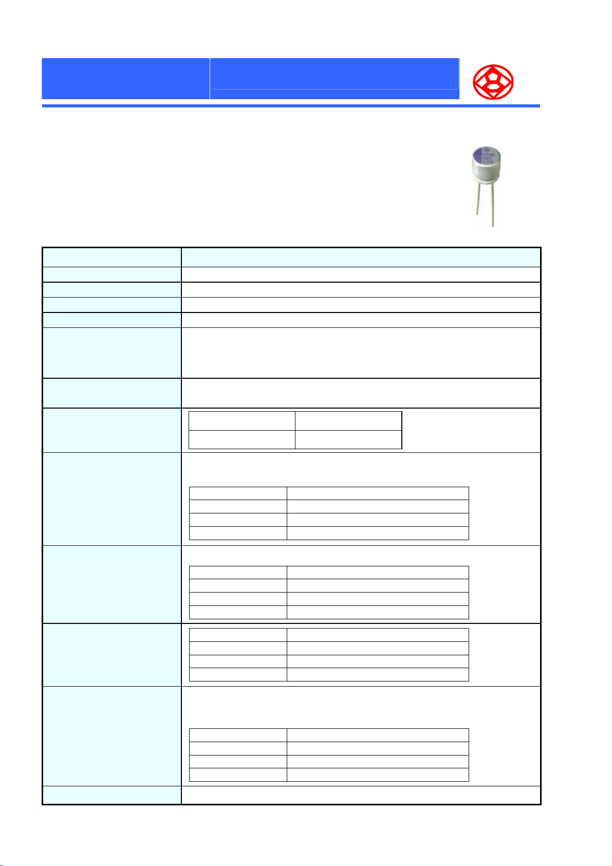
P
● Ultra Low ESR, High ripple current, High reliability, long life
● Rated voltage range : 2.5 to 16 Vdc
● 2000 hours at 105℃
● Suitable for DC – DC converters, voltage regulators and decouping applications
for computer motherboards
■ SPECIFICATIONS
Operating Temperature Range -55 ~ +105℃
Capacitance Tolerance ± 20 % (20℃、120Hz)
Dissipation Factor (tanδ) 0.12 (max.) (20℃、120Hz)
Surge Voltage Rated voltage × 1.15V
Leakage Current
O
P
C
O
P
C
O
S
R
S
R
S
R
Items Characteristics
N
N
N
S
e
S
e
S
e
r
i
e
s
r
i
e
s
r
i
e
s
I = 0.2CV . After 2 minutes application of rated voltage. ≦6.3ψ I = 0.5CV
I= Leakage Current (μA) C= Nominal Capacitance (μF) V= Rated Voltage
(If the leakage current is not stabilized,apply rated voltage for 120 minutes at 105℃)
Equivalent series resistance
( ESR )
High temperature
& Low temperature
Characteristic
Durability
High temperature & high
humidity
(Constant)
Resistance to Soldering heat
Flow method (260±5°C × 10s)
Please see the attached standard products list.
Z(-55℃)/Z(20℃) 0.75 ~ 1.25
Z(+105℃)/Z(20℃) 0.75 ~ 1.25
After applying the rate voltage for 2000 hours at 105℃ and then being stabilized at 20℃,
capacitors shall meet the following limits.
Capacitance Change Within ±20% of the initial value.
Dissipation Factor Not more than 150% of the specified value.
ESR Not more than 150% of the specified value.
Leakage Current Not more than the specified value.
After storing for 1000 hours at 60℃、90~95%R.H.
Capacitance Change Within ±20% of the initial value.
Dissipation Factor Not more than 150% of the specified value.
ESR Not more than 150% of the specified value.
Leakage Current Not more than the specified value.
Capacitance Change Within ±5% of the initial value.
Dissipation Factor Not more than the specified value.
ESR Not more than the specified value.
Leakage Current Not more than the specified value.
(100KHZ)
(20℃)
Surge Voltage Test
Failure Rate
The capacitors shall be subjected to 1000 cycles each consisting of charge with the surge
voltage specified at 105℃ for 30 seconds through a protective resistor(R=1kΩ) and discharge
for 5 minutes 30 seconds.
Capacitance Change Within ±20% of the initial value.
Dissipation Factor Not more than 150% of the specified value.
ESR Not more than 150% of the specified value.
Leakage Current Not more than the specified value.
1% per 1000 hours maximum (Confidence level 60% at 105℃)
12
Page 14
F
P
C
P
P
Size
Code
0808
C
C
S
S
S
O
O
O
R
R
R
F
F
P
P
P
■ STANDARD PRODUCTS
N
N
N
S
e
S
e
S
e
r
i
e
s
r
i
e
s
r
i
e
s
Rated
voltage
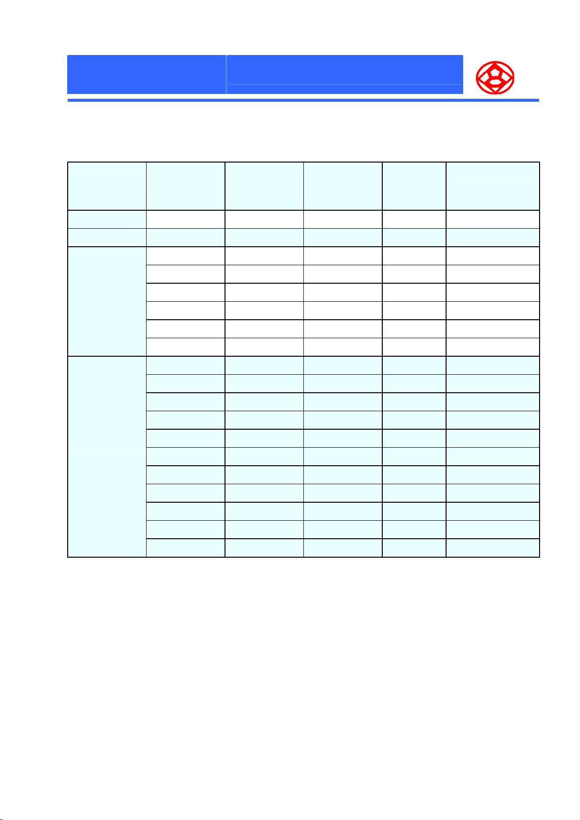
V. D C (µF) (105℃、100KHz) 20 , 100KHz℃
2.5 560 6100 7
Nominal capacitance
Max. permissible ripple
current
(mA r.m.s)
ESR
(mΩ) Max.
Part No.
2PSR561M0808
0809
0812
1012
2.5 820 6100 7
2.5 560 5600 7
2.5 820 5600 7
2.5 1000 6100 7
4 560 5600 7
6.3 220 5600 7
6.3 330 5600 7
2.5 1500 6100 7
4 820 6100 7
4 1200 6100 7
6.3 470 6100 7
6.3 560 6100 7
6.3 680 6100 7
6.3 820 6100 7
6.3 1000 6100 7
10 330 6100 7
2PSR821M0809
2PSR561M0812
2PSR821M0812
2PSR102M0812
4PSR561M0812
6PSR221M0812
6PSR331M0812
2PSR152M1012
4PSR821M1012
4PSR122M1012
6PSR471M1012
6PSR561M1012
6PSR681M1012
6PSR821M1012
6PSR102M1012
10PSR331M1012
10 470 6100 7
10 680 6100 7
13
10PSR471M1012
10PSR681M1012
Page 15
F
P
C
F
F
P
P
P
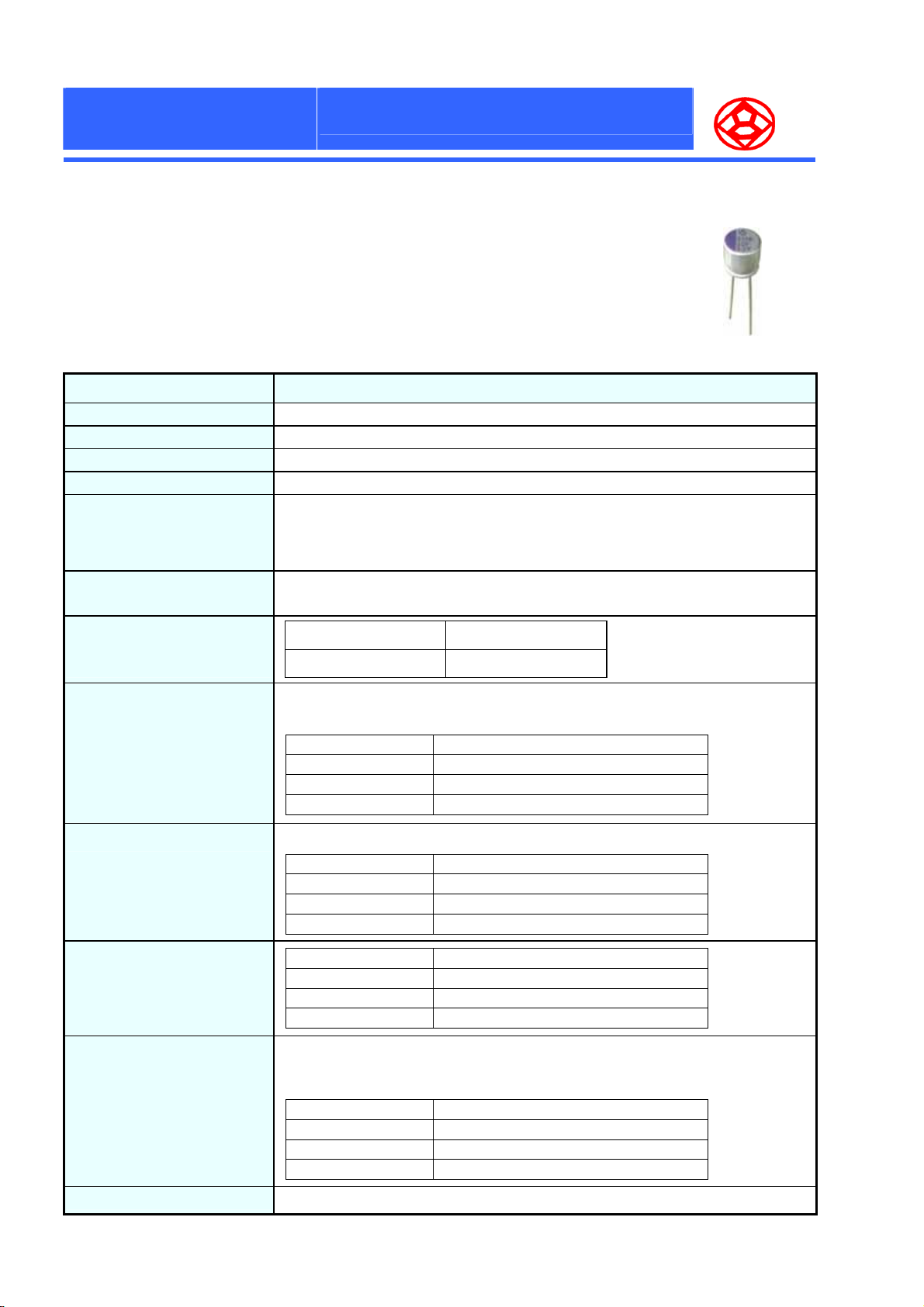
● Ultra Low ESR, High ripple current, High reliability, long life
● Rated voltage range : 2.5 to 16 Vdc
● 2000 hours at 105℃
● Suitable for DC – DC converters, voltage regulators and decouping applications
for computer motherboards
■ SPECIFICATIONS
Operating Temperature Range -55 ~ +105℃
Capacitance Tolerance ± 20 % (20℃、120Hz)
Dissipation Factor (tanδ) 0.12 (max.) (20℃、120Hz)
Surge Voltage Rated voltage × 1.15V
Leakage Current
O
P
C
O
P
C
O
S
B
S
B
S
B
Items Characteristics
N
N
N
S
e
S
e
S
e
r
i
e
s
r
i
e
s
r
i
e
s
I = 0.2CV . After 2 minutes application of rated voltage. ≦6.3ψ I = 0.5CV
I= Leakage Current (µA) C= Nominal Capacitance (µF) V= Rated Voltage
(If the leakage current is not stabilized,apply rated voltage for 120 minutes at 105 )℃
Equivalent series resistance
( ESR )
High temperature
& Low temperature
Characteristic
Durability
High temperature & high
humidity
(Constant)
Resistance to Soldering heat
Flow method (260±5°C × 10s)
Please see the attached standard products list.
Z(-55 )/Z(20 )℃℃ 0.75 ~ 1.25
Z(+105 )/Z(20 )℃℃ 0.75 ~ 1.25
After applying the rate voltage for 2000 hours at 105 and then ℃ being stabilized at 20 , ℃
capacitors shall meet the following limits.
Capacitance Change Within ±20% of the initial value.
Dissipation Factor Not more than 150% of the specified value.
ESR Not more than 150% of the specified value.
Leakage Current Not more than the specified value.
After storing for 1000 hours at 60℃、90~95%R.H.
Capacitance Change Within ±20% of the initial value.
Dissipation Factor Not more than 150% of the specified value.
ESR Not more than 150% of the specified value.
Leakage Current Not more than the specified value.
Capacitance Change Within ±5% of the initial value.
Dissipation Factor Not more than the specified value.
ESR Not more than the specified value.
Leakage Current Not more than the specified value.
(100KHZ)
(20 )℃
Surge Voltage Test
Failure Rate
The capacitors shall be subjected to 1000 cycles each consisting of charge with the surge
voltage specified at 105 ℃ for 30 seconds through a protective resistor(R=1kΩ) and discharge
for 5 minutes 30 seconds.
Capacitance Change Within ±20% of the initial value.
Dissipation Factor Not more than 150% of the specified value.
ESR Not more than 150% of the specified value.
Leakage Current Not more than the specified value.
1% per 1000 hours maximum (Confidence level 60% at 105 )℃
14
Page 16
F
P
C
P
P
Size
Code
0605
0809
1010
0812
1012
C
C
S
S
S
O
O
O
B
B
B
F
F
P
P
P
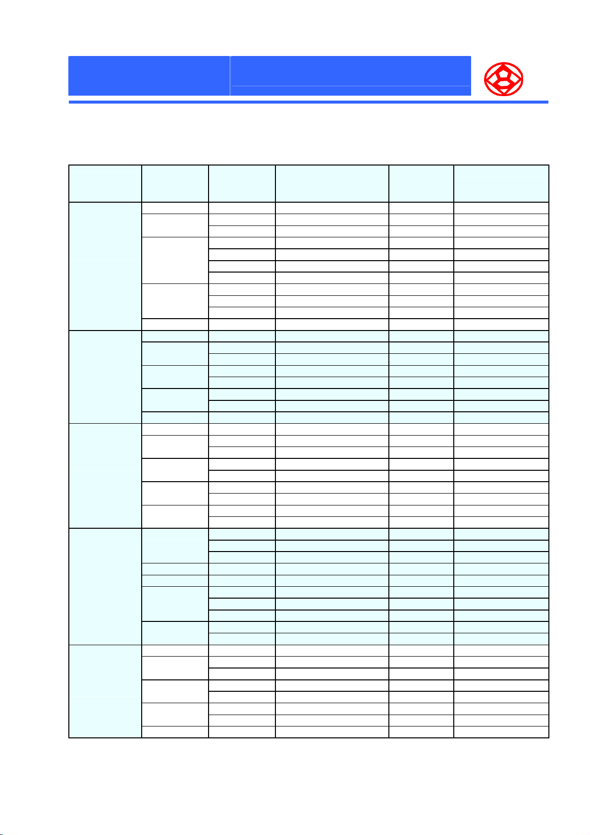
■ STANDARD PRODUCTS
N
N
N
S
S
S
e
r
i
e
s
e
r
i
e
s
e
r
i
e
s
Rated
voltage
V. D C (µF) (-55 to 105℃、100KHz to 300KHz) 20 , 100KHz℃
2.5 220 2550 25 2PSB221M0605
4
6.3
10
16 39 1620 50 16PSB390M0605
2.5 560 3100 23 2PSB561M0809
4
6.3
10
16 82 2200 40 16PSB820M0809
2.5 1000 4300 20 2PSB102M1010
4
6.3
10
16
2.5
4 560 4800 11 4PSB561M0812
6.3 470 4800 11 6PSB471M0812
10
16
2.5 1500 5600 10 2PSB152M1012
4
6.3
10
16 330 4800 16 16PSB331M1012
Nominal
capacitance
100 2500 25 4PSB101M0605
150 2500 25 4PSB151M0605
68 2450 25 6PSB680M0605
82 2450 25 6PSB820M0605
100 2450 25 6PSB101M0605
120 2450 25 6PSB121M0605
47 2300 25 10PSB470M0605
56 2300 25 10PSB560M0605
82 2300 25 10PSB820M0605
220 3050 23 4PSB221M0809
330 3050 23 4PSB331M0809
150 3050 23 6PSB151M0809
220 3050 23 6PSB221M0809
120 2850 23 10PSB121M0809
150 2850 23 10PSB151M0809
470 4200 20 4PSB471M1010
680 4200 20 4PSB681M1010
330 3800 20 6PSB331M1010
470 3800 20 6PSB471M1010
270 3500 20 10PSB271M1010
330 3500 20 10PSB331M1010
150 3100 30 16PSB151M1010
220 3100 30 16PSB221M1010
680 4800 11 2PSB681M0812
820 4800 11 2PSB821M0812
1000 4800 11 2PSB102M0812
390 4800 11 10PSB391M0812
270 4500 11 10PSB271M0812
330 4500 11 10PSB331M0812
180 3700 20 16PSB181M0812
220 3700 20 16PSB221M0812
820 5600 10 4PSB821M1012
1200 5600 10 4PSB122M1012
680 5600 10 6PSB681M1012
820 5600 10 6PSB821M1012
470 5400 10 10PSB471M1012
560 5400 10 10PSB561M1012
Max. permissible ripple current
(mA r.m.s)
ESR
(mΩ) Max.
Part No.
15
Page 17
F
P
C
F
F
P
P
P
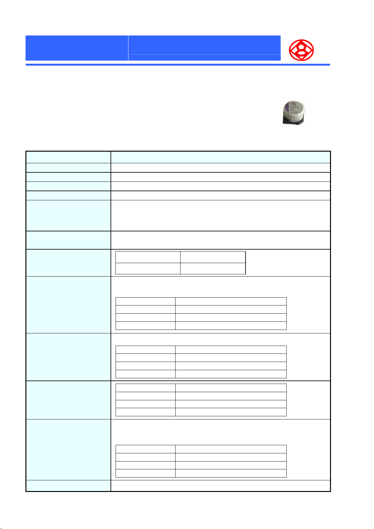
● Ultra Low ESR, High ripple current, High reliability, long life
● Rated voltage range : 2.5 to 10 Vdc
● 1000 hours at 125℃
● Suitable for DC – DC converters, voltage regulators and decouping applications
for computer motherboards
■ SPECIFICATIONS
Operating Temperature Range -55 ~ +125℃
Capacitance Tolerance ± 20 % (20℃、120Hz)
Dissipation Factor (tanδ) 0.12 (max.) (20℃、120Hz)
Surge Voltage Rated voltage × 1.15V
Leakage Current
O
P
C
O
P
C
O
V
H
V
H
V
H
Items Characteristics
N
N
N
S
S
S
e
r
i
e
s
e
r
i
e
s
e
r
i
e
s
I = 0.2CV . After 2 minutes application of rated voltage. ≦6.3ψ I = 0.5CV
I= Leakage Current (µA) C= Nominal Capacitance (µF) V= Rated Voltage
(If the leakage current is not stabilized,apply rated voltage for 120 minutes at 105 )℃
Equivalent series resistance
( ESR )
High temperature
& Low temperature
Characteristic
Durability
High temperature & high
humidity
(Constant)
Resistance to Soldering heat
Flow method (260±5°C × 10s)
Test method:
Please see the page 8 ( No. 3 )
Please see the attached standard products list.
Z(-55 )/Z(20 )℃℃ 0.75 ~ 1.25
Z(+125 )/Z(20 )℃℃ 0.75 ~ 1.25
After applying the rate voltage for 1000 hours at 125 and then being stabilized at 2℃ 0, ℃
capacitors shall meet the following limits.
Capacitance Change Within ±20% of the initial value.
Dissipation Factor Not more than 150% of the specified value.
ESR Not more than 150% of the specified value.
Leakage Current Not more than the specified value.
After storing for 1000 hours at 60℃、90~95%R.H.
Capacitance Change Within ±20% of the initial value.
Dissipation Factor Not more than 150% of the specified value.
ESR Not more than 150% of the specified value.
Leakage Current Not more than the specified value.
Capacitance Change Within ±5% of the initial value.
Dissipation Factor Not more than the specified value.
ESR Not more than the specified value.
Leakage Current Not more than the specified value.
(100KHZ)
(20 )℃
Surge Voltage Test
Failure Rate
The capacitors shall be subjected to 1000 cycles each consisting of charge with the surge
voltage specified at 105 ℃ for 30 seconds through a protective resistor(R=1kΩ) and discharge
for 5 minutes 30 seconds.
Capacitance Change Within ±20% of the initial value.
Dissipation Factor Not more than 150% of the specified value.
ESR Not more than 150% of the specified value.
Leakage Current Not more than the specified value.
1% per 1000 hours maximum (Confidence level 60% at 105 )℃
16
Page 18
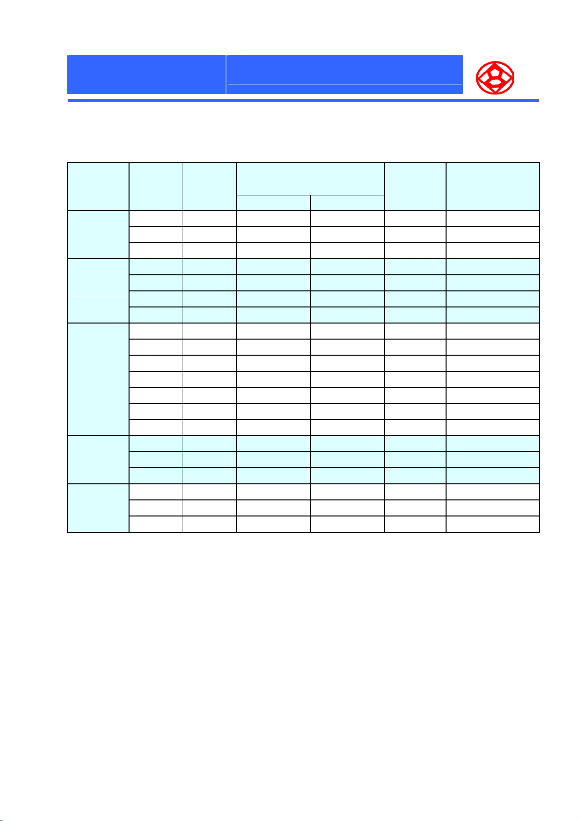
F
P
C
P
V
C
C
V
V
O
O
O
H
H
H
F
P
F
P
P
P
■ STANDARD PRODUCTS
Size
Code
0605
0809
1010
0812
1012
N
N
N
S
e
r
i
e
s
S
e
r
i
e
s
S
e
r
i
e
s
Rated
voltage
V. D C (µF) 105℃<To 125≦℃ To 105≦℃ 20 , 100KHz℃
10 56 540 1700 45 10PVH560M0605
6.3 82 540 1700 45 6PVH820M0605
4 150 580 1800 40 4PVH151M0605
10 120 820 2600 35 10PVH121M0809
6.3 150 820 2600 35 6PVH151M0809
6.3 220 820 2600 35 6PVH221M0809
4 330 820 2600 35 4PVH330M0809
10 270 1180 3800 25 10PVH271M1010
10 330 1180 3800 25 10PVH331M1010
6.3 330 1180 3800 25 6PVH331M1010
6.3 470 1180 3800 25 6PVH471M1010
4 470 1180 3800 25 4PVH471M1010
4 560 1180 3800 25 4PVH561M1010
4 680 1180 3800 25 4PVH681M1010
10 330 1270 4000 17 10PVH331M0812
6.3 470 1350 4300 15 6PVH471M0812
4 560 1450 4600 13 4PVH561M0812
10 560 1670 5300 13 10PVH561M1012
6.3 820 1740 5500 12 6PVH821M1012
4 1200 1740 5500 12 4PVH122M1012
Nominal
capacitance
Max. permissible ripple current
(mA r.m.s)
(-55 to 105℃、100KHz to 300KHz)
ESR
(mΩ) Max.
Part No.
17
Page 19
F
P
C
P
P
C
C
V
V
V
O
O
O
R
R
R
F
F
P
P
P
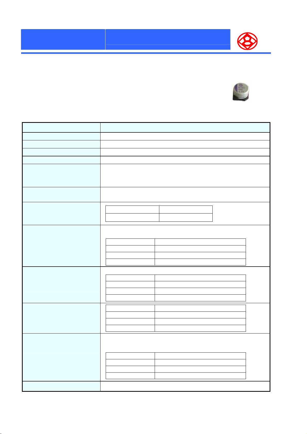
● Ultra Low ESR, High ripple current, High reliability, long life
● Rated voltage range : 2.5 to 10 Vdc
● 2000 hours at 105℃
● Suitable for DC – DC converters, voltage regulators and decouping applications
for computer motherboards
■ SPECIFICATIONS
Operating Temperature Range -55 ~ +105℃
Capacitance Tolerance ± 20 % (20℃、120Hz)
Dissipation Factor (tanδ) 0.12 (max.) (20℃、120Hz)
Surge Voltage
Leakage Current
Equivalent series resistance
( ESR )
N
S
e
S
e
S
e
r
i
e
s
r
i
e
s
r
i
e
s
N
N
Items Characteristics
Rated voltage × 1.15V
I = 0.2CV . After 2 minutes application of rated voltage. ≦6.3ψ I = 0.5CV
I= Leakage Current (µA) C= Nominal Capacitance (µF) V= Rated Voltage
(If the leakage current is not stabilized,apply rated voltage for 120 minutes at
Please see the attached standard products list
High temperature
& Low temperature
Characteristic
Durability
High temperature & high humidity
(Constant)
Resistance to Soldering heat
Flow method (260±5°C × 10s)
Test method:
Please see the page 8 ( No. 3 )
Surge Voltage Test
Z(-55 )/Z(20 )℃℃ 0.75 ~ 1.25
Z(+105 )/Z(20 )℃℃ 0.75 ~ 1.25
After applying the rate voltage for 2000 hours at 105 and then being stabilized at ℃
20℃, capacitors shall meet the following limits.
Capacitance Change Within ±20% of the initial value.
Dissipation Factor Not more than 150% of the specified value.
ESR Not more than 150% of the specified value.
Leakage Current Not more than the specified value.
After storing for 1000 hours at 60℃、90~95%R.H.
Capacitance Change Within ±20% of the initial value.
Dissipation Factor Not more than 150% of the specified value.
ESR Not more than 150% of the specified value.
Leakage Current Not more than the specified value.
Capacitance Change Within ±5% of the initial value.
Dissipation Factor Not more than the specified value.
ESR Not more than the specified value.
Leakage Current Not more than the specified value.
The capacitors shall be subjected to 1000 cycles each consisting of charge with the
surge voltage specified at 105 ℃ for 30 seconds through a protective resistor(R=1kΩ)
and discharge for 5 minutes 30 seconds.
Capacitance Change Within ±20% of the initial value.
Dissipation Factor Not more than 150% of the specified value.
ESR Not more than 150% of the specified value.
Leakage Current Not more than the specified value.
(100KHZ)
(20 )℃
Failure Rate
1% per 1000 hours maximum (Confidence level 60% at 105 )℃
18
Page 20
F
P
C
P
V
C
C
V
V
O
O
O
R
R
R
F
P
F
P
P
P
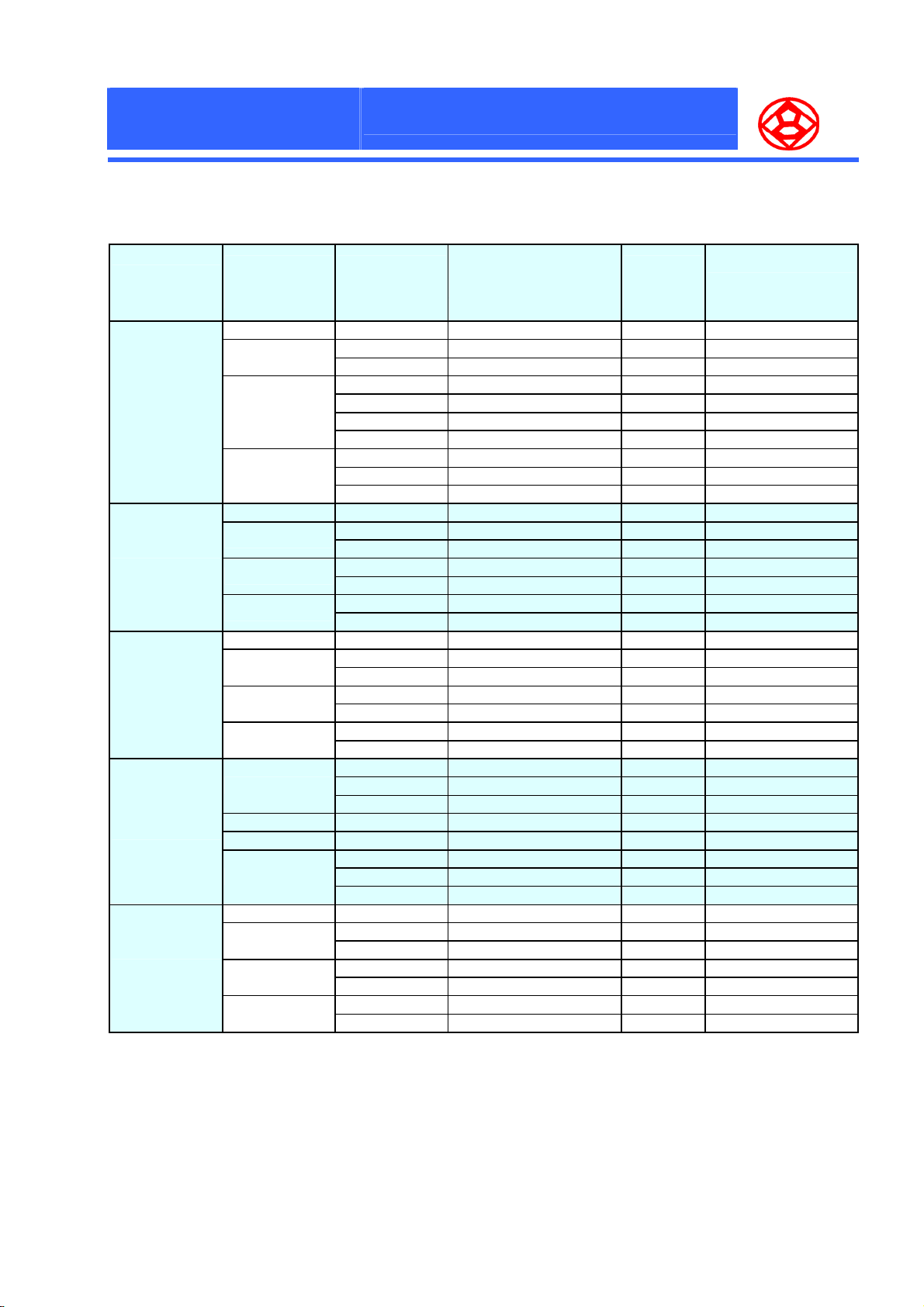
■ STANDARD PRODUCTS
N
N
N
S
S
e
r
i
e
s
e
r
i
e
s
S
e
r
i
e
s
Size
Code
0605
0809
1010
0812
1012
Rated
voltage
V. D C
2.5 220 2550 25 2PVR221M0605
4
6.3
10
2.5 560 3100 23 2PVR561M0809
4
6.3
10
2.5 1000 4300 20 2PVR102M1010
4
6.3
10
2.5
4 560 4800 11 4PVR561M0812
6.3 470 4800 11 6PVR471M0812
10
2.5 1500 5600 10 2PVR152M1012
4
6.3
10
Nominal
capacitance
(µF)
100 2500 25 4PVR101M0605
150 2500 25 4PVR151M0605
68 2450 25 6PVR680M0605
82 2450 25 6PVR820M0605
100 2450 25 6PVR101M0605
120 2450 25 6PVR121M0605
47 2300 25 10PVR470M0605
56 2300 25 10PVR560M0605
82 2300 25 10PVR820M0605
220 3050 23 4PVR221M0809
330 3050 23 4PVR331M0809
150 3050 23 6PVR151M0809
220 3050 23 6PVR221M0809
120 2850 23 10PVR121M0809
150 2850 23 10PVR151M0809
470 4200 20 4PVR471M1010
680 4200 20 4PVR681M1010
330 3800 20 6PVR331M1010
470 3800 20 6PVR471M1010
270 3500 20 10PVR271M1010
330 3500 20 10PVR331M1010
680 4800 11 2PVR681M0812
820 4800 11 2PVR821M0812
1000 4800 11 2PVR102M0812
390 4800 11 10PVR391M0812
270 4500 11 10PVR271M0812
330 4500 11 10PVR331M0812
820 5600 10 4PVR821M1012
1200 5600 10 4PVR122M1012
680 5600 10 6PVR681M1012
820 5600 10 6PVR821M1012
470 5400 10 10PVR471M1012
560 5400 10 10PVR561M1012
Max. permissible ripple current
(mA r.m.s)
(-55 to 105℃、100KHz to 300KHz)
ESR
(mΩMax.)
20 , 100KHz℃
Part No.
19
Page 21
FPCON
Technical Data
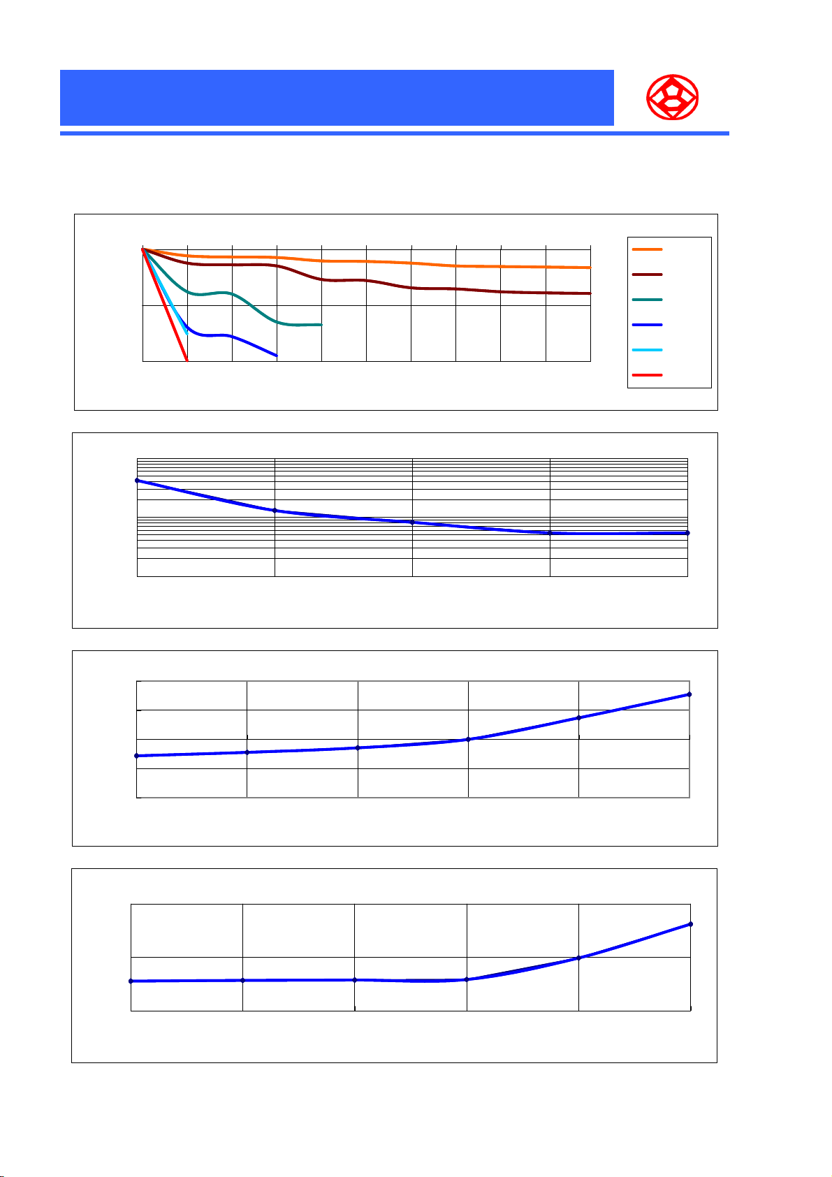
2PSR561M0808
0
Temperature Acceleration Test (Endurance)
105℃
125℃
-10
-20
Capacitance change(%)
0 100 200 500 1000 1500 2000 2500 3000 3500 4000
Time (H)
100
10
ESR (mΩ)
1
120 1K 10K 100K 200K
20
Frequency Character
Frequency (Hz)
Temperature Character
135℃
145℃
155℃
160℃
10
0
-10
Capacitance change(%)
-20
-55 -40 -25 20 85 105
Temperature(℃)
Temperature Character
10
5
DF (%)
0
-55 -40 -25 20 85 105
Temperature(℃)
20
Page 22
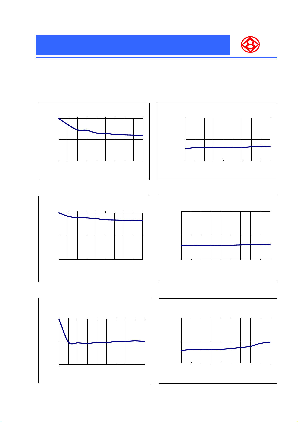
FPCON
Technical Data
2PSR561M0808
Endurance (125°C, 2.5V applied)
0
-10
Capacitancechange(%)
-20
0 500 1000 1500 2000 2500 3000 3500 4000 5000
Time (H)
Endurance (105°C, 2.5V applied)
0
-10
Capacitance change(%)
-20
0 500 1000 1500 2000 2500 3000 3500 4000 5000
Endurance (125°C, 2.5V applied)
0.0200
0.0100
ESR change(Ω)
0.0000
0 500 1000 1500 2000 2500 3000 3500 4000 5000
Time (H)
Endurance (105°C, 2.5V applied)
0.02
0.01
ESR change (Ω)
0
0 500 1000 1500 2000 2500 3000 3500 4000 5000
Time (H)
Load & ripple current superimposed
character (105℃6100mA)
0
-10
Capacitance change(%)
-20
0 500 1000 1500 2000 2500 3000 3500 4000 5000
Time (H)
Time (H)
Load & ripple current superimposed character
(105℃6100mA)
0.02
0.01
ESR change(Ω)
0
0 500 1000 1500 2000 2500 3000 3500 4000 5000
Time (H)
21
 Loading...