

Page 1
www.fairchildsemi.com
FM75
Low Voltage 2-Wire Digital Temperature Sensor
with Thermal Alarm
Features
• User Configurable to 9, 10, 11 or 12-bit Resolution
• Precision Calibrated to ±1°C from 0°C to 100°C Typical
• Temperature Range: –40°C to 125°C
• Low Operating Current (less than 250µA)
• Low Self Heating (0.2°C max in still air)
• Operating Voltage Range: 2.7V to 5.5V
Applications
• Battery Management
• FAX Management
• Printers
• Portable Medical Instruments
•HVAC
• Power Supply Modules
• Disk Drives
• Computers
• Automotive
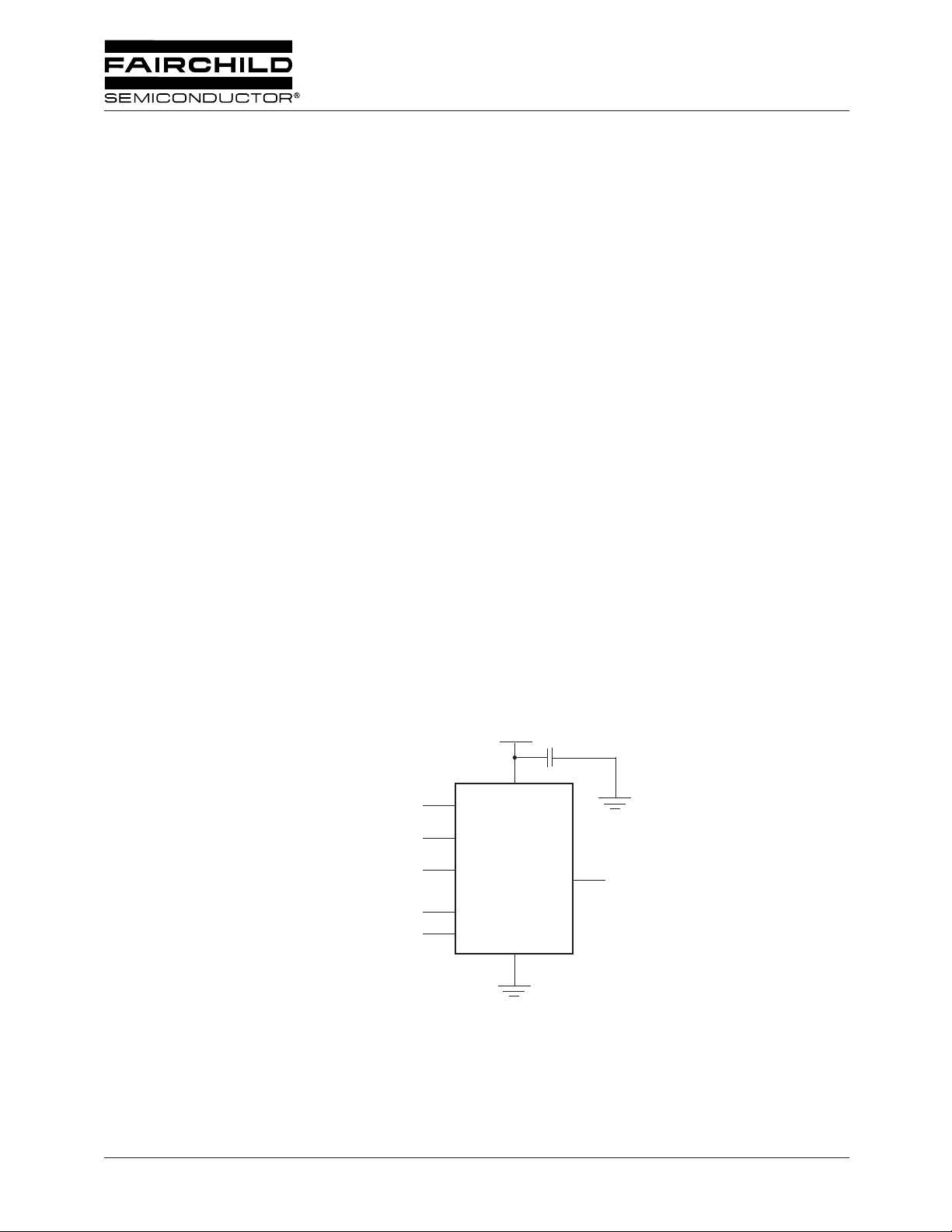
Application Diagram
Description
Within the FM75 are: a high-precision CMOS temperature
sensor, a Delta-Sigma analog-to-digital converter and a
SMBus compatible serial digital interface. Typical accuracy
is ±2°C over the full temperature range of –40°C to 125°C
and to ±1°C over the range of 0°C to 100°C, with 9- to 12-bit
resolution. Default resolution is 9 bits.
Thermal Alarm output, OS (Over-limit Signal) supports
Interrupt and Comparator modes. OS is active, if the
user-programmable trip-temperature is exceeded. When
the temperature falls below the trip-temperature plus the
user-programmable hysteresis limit, OS is disabled.
Available packages are surface mount SOIC-8 (SOP-8) and
MSOP-8.
User
Programmable
Address
SMBus
Interface
A0
A1
A2
SDA
SCL
7
6
5
1
2
2.7 to 5.5V
8
FM75
8 Pin
Configuration
4
3
O.S.
REV. 1.0.4 10/3/02
Page 2
FM75 PRODUCT SPECIFICATION
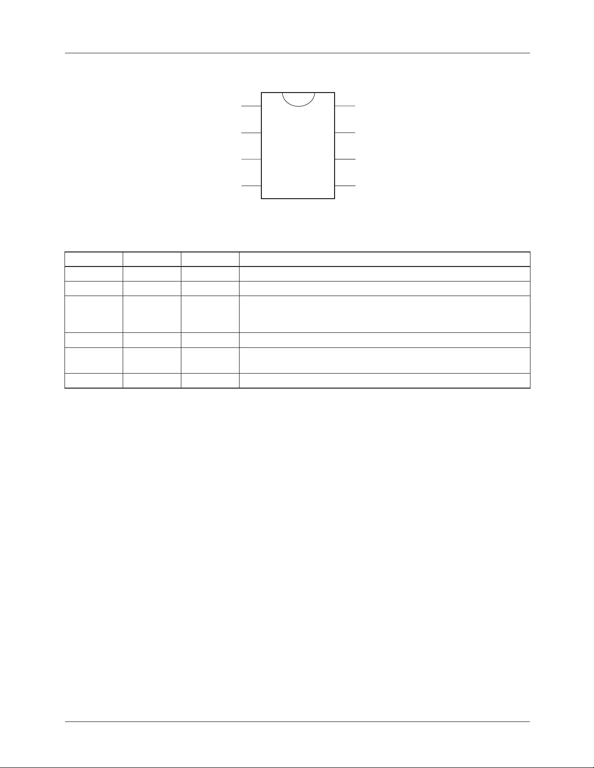
Pin Assignments
SDA
SCL
1
2
8
7
V
A0
DD
FM75
O.S.
GND
3
4
6
5
A1
A2
Pin Descriptions
Pin # Name Direction Description
1 SDA Input/Output Serial Data. Open drain to I/O-data pin for two-wire interface.
2 SCL Input
3 O.S. Output
4 GND Supply
5, 6, 7 A0, A1, A2 Input
8V
DD
Supply
Serial Clock. Clock for 2-wire serial interface.
Over-Limit Signal. Open drain thermostat output that indicates if the
temperature has exceeded user-programmable limits. Default is
active low.
Ground
Address LSBs. User selectable address pins for the 3 LSBs of the
serial interface address.
Supply Voltage
2
REV. 1.0.4 10/3/02
Page 3
≤
PRODUCT SPECIFICATION FM75
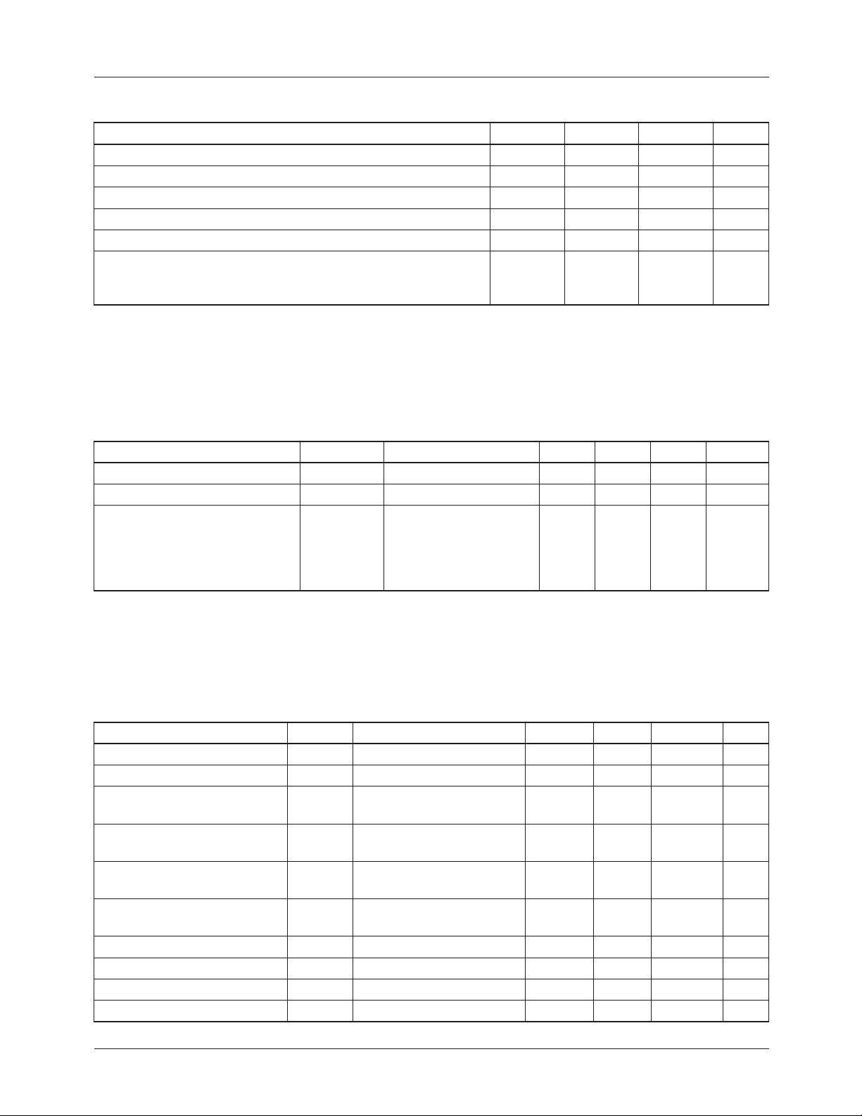
Absolute Maximum Ratings
1
Parameter Min. Typ. Max. Units
Supply Voltage +7 V
Output Voltage V
+ 0.5 V
CC
Output Current 10 mA
Storage Temperature Range -60 +150 °C
Lead Soldering Temperature 220 °C
2
ESD
Human Body Model
Machine Model
Notes:
1. Absolute maximum ratings are limits beyond which operation may cause permanent damage to the device. These are stress
ratings only; functional operation at or above these limits is not implied.
2. Human Body Model: 100pF capacitor discharged through a 1.5k Ω resistor into each pin. Machine Model: 200pF capacitor
discharged directly into each pin.
Electrical Characteristics
(-40°C ≤ T
+125°C, V
A
= 5.0V unless otherwise noted. Specifications subject to change without notice.)
CC
3
2000
250
V
V
Parameter Symbol Conditions Min. Typ. Max. Units
Specified Temperature Range T
Temperature Conversion Time
Accuracy
Notes:
3. These specifications are guaranteed only for the test conditions listed.
4. This specification only indicates how often temperature information is updated to the Temperature Register. The FM75 can
be read at any time without interrupting the temperature conversion process.
5. Accuracy (expressed in °C) = Difference between the FM75 output temperature and the measured temperature.
5
4
MIN
, T
MAX
T
= 0°C
A
T
= +25°C
A
T
= +100°C
A
T
= –40°C (T
A
T
= +125°C (T
A
MIN
MAX
-40 +125 °C
90 ms
-1
-1
-3
)
)
-4
-4
+1
+1
+3
+4
+4
°C
Logic Electrical Characteristics
Parameter Symbol Conditions Min Typ Max Units
Min. Input Voltage Logic High V
Max. Input Voltage Logic Low V
Max. Output Voltage Logic
Low
Quiescent Supply Current I
Shutdown Current I
Input Leakage Current I
Output Sink Current I
Output Leakage Current I
Output Transition Time t
Input Capacitance C
REV. 1.0.4 10/3/02
IH
IL
V
OL
DD
DD-SD
IN
OL
LEAK
F
IN
V
V
= 5V, I
DD
= 3V, I
DD
= -3mA
OL
= -1.5mA
OL
Interface inactive R/W
Activity on SDA
Interface inactive R/W
Activity on SDA
V
= 0V or 5V, T
IN
-40°C < T
T
= 25°C, V
A
V
= 5V, V
OH
C
= 400pF, I
L
< 125°C
A
= 25°C
A
= 0.4V 3 mA
OL
= 0V 0.001 5 µA
DD
= -3mA 250 ns
OL
All Digital Inputs 20 pF
V
x 0.7 V
DD
-0.3 V
250
350
0.15
83
+ 0.5 V
DD
x 0.3 V
DD
0.36
0.36
500
700
1
150
±0.1
±1.0
V
V
µA
µA
µA
3
Page 4
FM75 PRODUCT SPECIFICATION
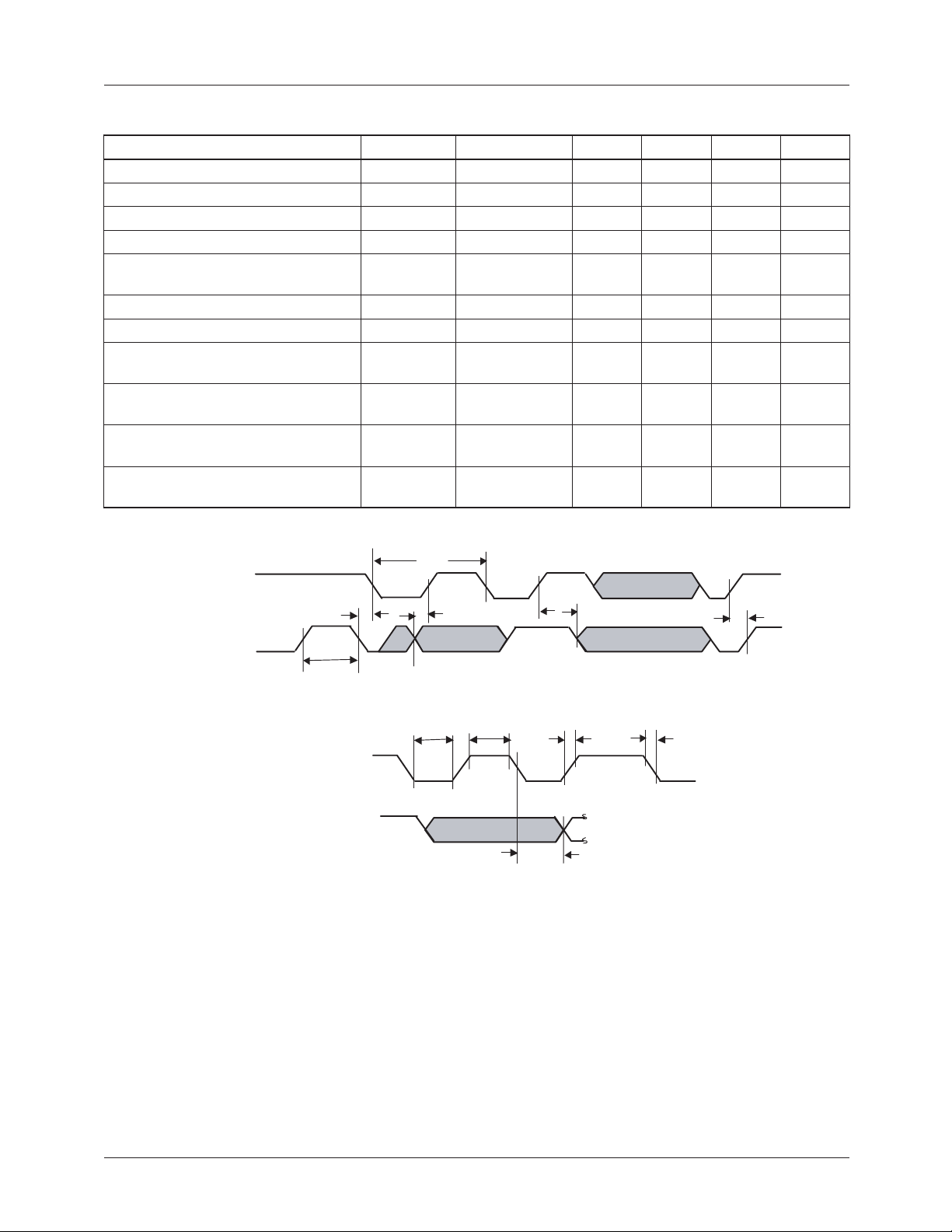
Serial Port Timing
Parameter Symbol Conditions Min. Typ. Max. Units
SCL Clock Period t
SCL Clock Transition Time t
T:LH
SCL Clock Low Period t
SCL Clock High Period t
Bus free time between a Stop and
a new Start Condition
Data in Set-up to SCL High t
Data Out Stable after SCL Low t
SCL Low Set-up to SDA Low
t
(Repeated Start Condition)
SCL High Hold after SDA Low
t
(Start Condition)
SDA High after SCL High
t
(Stop Condition
Time in which a FM75 must be
operational after a power-on reset
SCL
, t
T:HL
LOW
HIGH
t
1.0 µs
BUF
SU:DAT
HD:DAT
SU:STA
HD:STA
SU:STO
t
POR
1.0 100 µs
300 ns
0.470 µs
0.400 50 µs
100 ns
0ns
100 ns
100 ns
100 ns
500 ms
t
SCL
SCL
SDA
Data In
t
HD:STA
t
BUF
t
SU:DAT
t
SU:STA
t
SU:STO
t
LOW
t
HIGH
t
T:LH
t
T:HL
SCL
90%
90%
10% 10%
SDA
Data Out
t
HD:DAT
4
REV. 1.0.4 10/3/02
Page 5
PRODUCT SPECIFICATION FM75
Basic Operation
The FM75 temperature sensing circuitry continuously
produces an analog voltage that is proportional to the device
temperature. At regular intervals the FM75 converts the
analog voltage to a two’s complement digital value, which is
placed into the temperature register.
The FM75 has an SMBus compatible digital serial interface
which allows the user to access the data in the temperature
register at any time. In addition, the serial interface gives the
user easy access to all other FM75 registers to customize
operation of the device.
The FM75 temperature-to-digital conversion can have 9,
10, 11, or 12-bit resolution as selected by the user, providing
0.5°C, 0.25°C, 0.125°C, and 0.0625°C temperature
resolution, respectively. At power-up the default conversion
resolution is 9-bits. The conversion resolution is controlled
by the R0 and R1 bits in the Configuration Register.
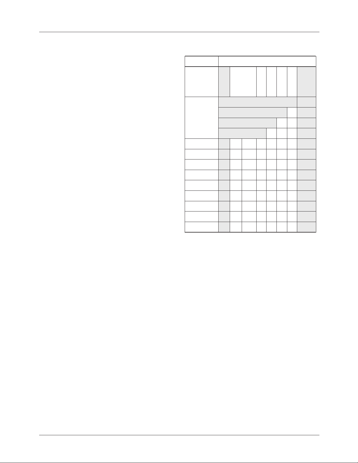
Table 1 gives examples of the relationship between the
output digital data and the external temperature. The 9-bit,
10-bit, 11-bit and 12-bit columns in Table 1 indicate the
right-most bit in the output data stream that can contain
temperature information for each conversion accuracy.
Since the output digital data is in two’s-complement format,
the most significant bit of the temperature is the “sign” bit.
If the sign bit is a zero, the temperature is positive and if the
sign bit is a one, the temperature is negative.
Table 1. Relationship Between Temperature and
Digital Output
Temperature
llA
C°521+
C°5260.001+
C°521.05+
C°52.21+
C°0
C°5.02-
C°52.33-
C°5260.54-
C°55-
giS
serutarepmeT
011110110000 0000
001100100001 0000
011001000010 0000
000000110100 0000
000000000000 0000
101111011000 0000
110101111100 0000
110101001111 0000
100110010000 0000
Digital Output
forebmuN
desustib
yb
noisrevnoc
tib9tib01tib11tib
noituloser
noituloseRtiB-21 0000
noituloseRtiB-11 00000
noituloseRtiB-10 00 0000
noituloseRtiB-90000000
21
syawlA
orez
The FM75 has a Shutdown Mode that reduces the operating
current of the FM75 to 150nA. This mode is controlled by
the SD bit in the configuration register.
Power Up Default Conditions
The FM75 always powers up in the following default state:
• Thermostat mode: Comparator Mode
• O.S. polarity: active low
• Fault tolerance: 1 fault (i.e., F0 = 0 and F1 = 0 in the
Configuration Register)
•T
= 80°C
OS
•T
HYST
= 75°C
• Register pointer: 00 (Temperature Register)
• Conversion resolution: 9 bits (i.e., R0 = 0 and R1 = 0 in
the Configuration Register)
After power up these conditions can be reprogrammed via
the serial interface. Refer to the Serial Data Bus Operation
section for FM75 programming instructions.
Thermal Alarm Function
The FM75 thermal alarm function provides user programmable thermostat capability and allows the FM75 to function
as a stand alone thermostat without using the serial interface.
The Over-Limit Signal (O.S.) output is the alarm output. This
signal is an open drain output, and at power-up this pin is
configured with active-low polarity.
The O.S. polarity is controlled by the POL bit in the
Configuration Register. The user-programmable upper
trip-point temperature for the thermal alarm is stored in
the T
Register, and the user-programmable hysteresis tem-
OS
perature (i.e., the lower trip point) is stored in the T
HYST
Register.
The thermal alarm has two modes of operation: Comparator
Mode and Interrupt Mode. At power-up the default is
Comparator Mode. The alarm mode is controlled by the
CMP/INTR bit in the Configuration Register.
Fault Tolerance
For both Comparator and Interrupt modes, the alarm “fault
tolerance” setting plays a role in determining when the O.S.
output will be activated. Fault tolerance refers to the number
of consecutive times an error condition must be detected
before the user is notified. Higher fault tolerance settings can
help eliminate false alarms caused by noise in the system.
The alarm fault tolerance is controlled by bits F0 and F1 in
the Configuration Register. These bits can be used to set
the fault tolerance to 1, 2, 4 or 6 as shown in Table 4. At
power-up, these bits both default to 0 (fault tolerance = 1).
REV. 1.0.4 10/3/02
5
Page 6
FM75 PRODUCT SPECIFICATION
Comparator Mode
In Comparator Mode, each time a temperature-to-digital
(T-to-D) temperature conversion occurs, the new digital temperature is compared to the value stored in the T
T
registers. If a fault tolerance number of consecutive
HYST
OS
and
temperature measurements are greater than the value stored
in the T
register, the O.S. output will be activated.
OS
For example, if bits F1 and F0 are equal to “10” (fault
tolerance = 4), four consecutive temperature measurements
must exceed T
to activate the O.S. output. Once the O.S
OS
output is active, it will remain active until the first time the
measured temperature drops below the temperature stored in
the T
register. The operation of the alarm in Comparator
HYST
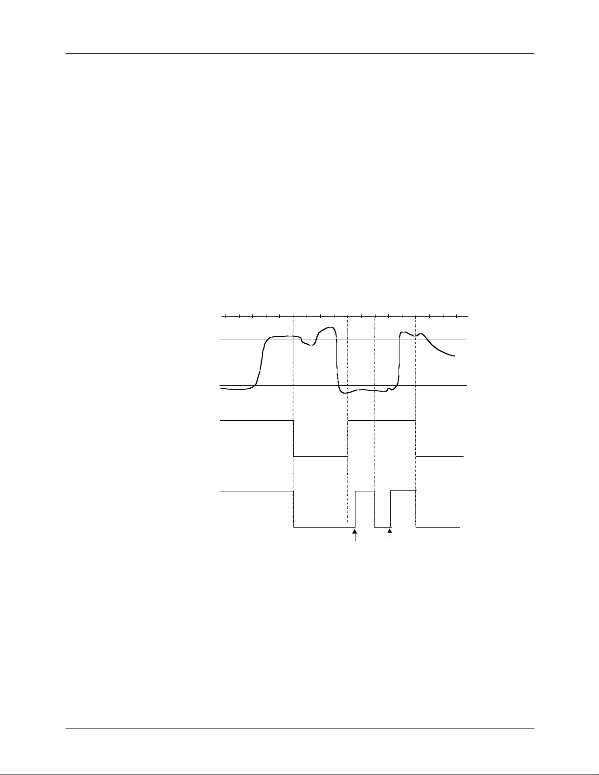
Mode with fault tolerance=2 is illustrated in Figure 1.
Temperature-to-Digital
Conversion
TOS
Interrupt Mode
In Interrupt Mode the O.S. output will first become active
after a fault tolerance number of consecutive temperature
measurements exceed the value stored in the T
(similar to Comparator Mode). Once O.S. is active, it can
only be cleared by a user read from any of the FM75
registers (Temperature, Configuration, T
OS
putting the FM75 into Shutdown Mode (i.e., by setting the
shutdown bit in the Configuration Register to “1”). Once
cleared, the O.S. output can only be activated the next time
by a fault tolerance number of consecutive temperature
measurements that are lower than the value stored in T
Again, once it is activated the O.S. output can only be
deactivated by a user read or shutdown. Thus, in Interrupt
Mode the activate/clear cycle for O.S. has the following
pattern: temperature > T
clear, temperature > T
, clear, temperature < T
OS
, clear, etc. The operation of the
OS
alarm in Interrupt Mode with fault tolerance=2 is also
illustrated in Figure 1.
, or T
register
OS
HYST
HYST
) or by
HYST
,
.
T
HYST
O.S. (Comparator Mode)
O.S. (Interrupt Mode)
Figure 1. Thermal Alarm Operation in Comparator and Interrupt Modes
For this example:
Fault Tolerance = 2
Output Polarity = Active Low
Read (or Shutdown)
6
REV. 1.0.4 10/3/02
Page 7

PRODUCT SPECIFICATION FM75
Registers
The FM75 contains the following five registers:
1. Command Register
2. Temperature Register
3. Configuration Register
4. Over-Limit-Signal Temperature Register (TOS)
5. Hysteresis Temperature Register (T
All of these registers can be accessed by the user via the
digital serial interface at any time (see Serial Interface
Operation for instructions). A detailed description of these
registers and their functions is provided in the following
paragraphs. A diagram of the register hierarchy is shown in
Figure 2.
SDA
Serial Interface
HYST
SCL
)
Read/Write
Data
Command Register
The Command Register is a one-byte (8-bit) write-only
register. The data stored in the Command Register indicates
which of the other four registers (Temperature, Configuration, T
write to during an upcoming operation. In other words the
Command Register “points” to the selected register as shown
in Figure 2.
The Command Register is illustrated in Figure 3. The P1 and
P0 bits of the Command Register determine which register is
to be accessed as shown in Table 2. The six MSBs of the
Command Register must always be zero. Writing a 1 into
any of these bits will cause the current operation to be
terminated.
The Command Register retains pointer information between
operations. Therefore, this register only needs to be updated
once for consecutive read operations from the same register.
All bits in the Command Register default to zero at
power-up.
, or T
OS
Temperature Register
Command Reg. = 00000000
) the user intends to read from or
HYST
2-byte Read Only
Command
(‘Pointer’)
Data
Command Register
1-byte Write Only
MSB
0
0
0
Figure 3. Command Register Format
000
Configuration Register
Figure 2. FM75 Register Hierarchy
Table 2. Register Assignments for Command
Bits P1 and P2
Register P1 P0
P1
LSB
P0
Temperature Register 0 0
Configuration Register 0 1
T
Register 1 0
HYST
TOS Register 1 1
1-byte Read/Write
Command Reg. = 00000001
T
Register
HYST
2-byte Read/Write
Command Reg. = 00000010
Register
T
OS
2-byte Read/Write
Command Reg. = 00000011
REV. 1.0.4 10/3/02
7
Page 8
FM75 PRODUCT SPECIFICATION
Temperature Register
The Temperature Register is a two-byte (16-bit) read-only
register. Digital temperatures from the T-to-D converter are
stored in the Temperature Register in two’s complement
format, and the contents of this register are updated at regular
intervals—i.e., each time the T-to-D conversion is finished.
The user can read data from the Temperature Register at any
time. When a T-to-D conversion is completed, the new data is
loaded into a comparator buffer to evaluate fault conditions,
and will update the Temperature Register if a read cycle is
not ongoing. The FM75 is continuously evaluating fault
conditions regardless of read or write activity on the bus. If a
read is ongoing, the previous temperature will be read. The
readable temperature will be updated upon the completion of
the next T-to-D conversion that is not masked by a read
cycle.
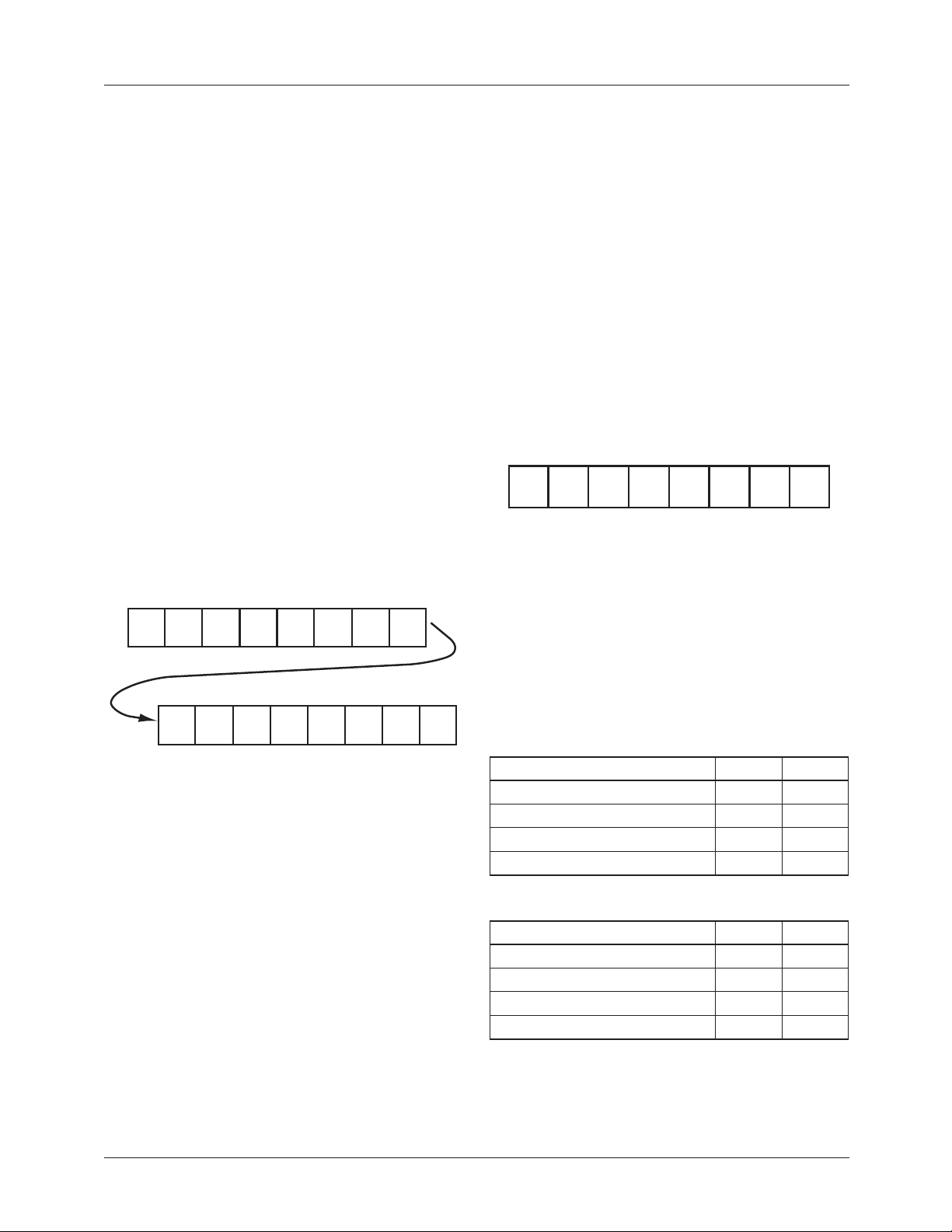
The Temperature Register is illustrated in Figure 4. Depending on the resolution of the T-to-D conversion, the 9, 10,
11 or 12 MSBs of the register will contain temperature data.
All unused bits following the digital temperature will be
zero. The MSB position of the Temperature Register always
contains the sign bit for the digital temperature and bit 14
contains the temperature MSB. All bits in the Temperature
Register default to zero at power-up.
TMSB
7
10-bit
13 12 11
T
TTT
6
5
11-bit
LSB
LSB
4
12-bit
LSB
10 9
T
2
3
00
T
1
LSB
0
0
MSB814
SB
9-bit
LSB
Configuration Register
The Configuration Register is a one-byte (8-bit) read/write
register (see Figure 5). This register allows the user to control
the FM75 Shutdown Mode as well as the following thermal
alarm features: polarity, operating mode, and fault tolerance.
The Configuration Register contains two bits that set the fault
tolerance trip point. The fault tolerance trip point is the number of consecutive times the internal circuit reads the temperature and finds the temperature outside the limits
programmed. The programmed limits are defined by the T
Register for the upper limit, and by the T
the lower limit. Table 4 shows the relationship between F1
and F0 and the number of consecutive errors or “trips”
needed to activate the alarm. The Configuration Register also
contains the two bits that set the T-to-D conversion resolution
to 9, 10, 11, or 12 bits. Table 3 shows the relationship
between R1 and T0 and the conversion resolution. All bits in
the configuration register default to zero at power-up.
MSB
X
R1
R1 = Resolution bit 1. (See Table 3)
R0 = Resolution bit 0. (See Table 3)
F1 = Fault tolerance bit 1. (See Table 4)
F0 = Fault tolerance bit 0. (See Table 4)
POL = O.S. output polarity. 0 = active low, 1 = active high.
CMP/INT = Thermostat mode. 0 = comparator mode,
1 = interrupt mode.
SD = Shutdown. 0 = normal operation, 1 = shutdown
mode.
Figure 5. Configuration Register Format
Table 3. Conversion Resolution Settings
543
6
R0 F1 F0
POL
Register for
HYST
21
CMP/
INT
OS
LSB
SD
SB = Two’s complement sign bit
TMSB = Temperature MSB
T = Temperature data
9-bit LSB = Temperature LSB for 9-bit conversions
10-bit LSB = Temperature LSB for 10-bit conversions
11-bit LSB = Temperature LSB for 11-bit conversions
12-bit LSB = Temperature LSB for 12-bit conversions
Figure 4. Temperature Register Format
8 REV. 1.0.4 10/3/02
A-to-D Conversion Resolution R1 R0
9 Bits 0 0
10 Bits 0 1
11 Bits 1 0
12 Bits 1 1
Table 4. Fault Tolerance Settings
Fault Tolerance R1 R0
100
201
410
611
Page 9
PRODUCT SPECIFICATION FM75
Over-Limit-Signal Temperature Register (TOS)
The TOS Register is a two-byte (16-bit) read/write register
that stores the user-programmable upper trip-point
temperature for the thermal alarm in two’s-complement
format. At power-up this register defaults to 80°C
(i.e., 0101 0000 0000 0000).
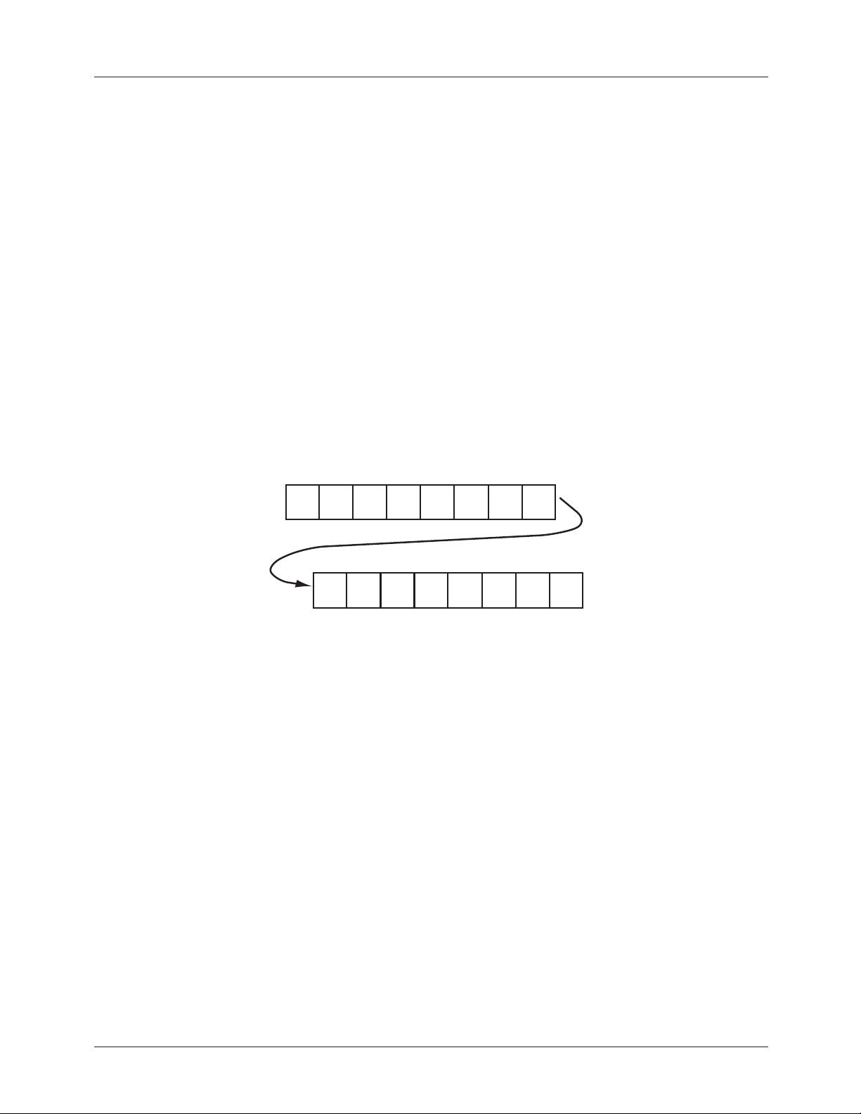
The format of the TOS register is identical to that of the
Temperature Register (see Figure 6). The 4 LSBs of the TOS
Register are hardwired to zero, so data written to these
register bits will be ignored. The MSB position of the TOS
Register contains the sign bit for the digital temperature and
bit 14 contains the temperature MSB.
The resolution setting for the T-to-D conversion determines
how many bits of the TOS Register are used by the thermal
alarm. For example, for 9-bit conversions the trip-point
temperature is defined by the 9 MSBs of the T
and all remaining bits are “don’t cares.”
.
MSB814
SB
OS
TMSB
register,
13 12 11
T
TTT
Hysteresis Temperature Register (T
The T
Register is a two-byte (16-bit) read/write
HYST
HYST
)
register that stores the user programmable lower trip-point
temperature for the thermal alarm in two’s-complement
format. At power-up this register defaults to 75°C (i.e., 0100
1011 0000 0000).
The T
register is illustrated in Figure 6. The format of
HYST
this register is the same as that of the Temperature Register.
The 4 LSBs of the T
register are hardwired to zero, so
HYST
data written to these bits is ignored.
The resolution setting for the T-to-D conversion determines
how many bits of the T
Register are used by the thermal
HYST
alarm. For example, for 9-bit conversions the hysteresis
temperature is defined by the 9 MSBs of the T
HYST
Register,
and all remaining bits are “don’t cares.”
10 9
T
T
6
7
9-bit
10-bit
LSB
SB = Two’s complement sign bit
TMSB = Temperature MSB
T = Temperature data
9-bit LSB = Temperature LSB for 9-bit conversions
10-bit LSB = Temperature LSB for 10-bit conversions
11-bit LSB = Temperature LSB for 11-bit conversions
12-bit LSB = Temperature LSB for 12-bit conversions
Figure 6. T
11-bit
LSB
Register and TOS Register Format
HYST
5
LSB
4
12-bit
LSB
2
3
00
1
0
LSB
0
REV. 1.0.4 10/3/02 9
Page 10

FM75 PRODUCT SPECIFICATION
Serial Data Bus Operation
General Operation
Writing to and reading from the FM75 registers is accomplished via the SMBus-compatible two-wire serial interface.
SMBus protocol requires that one device on the bus initiates
and controls all read and write operations. This device is
called the “master” device. The master device also generates
the SCL signal which is the clock signal for all other devices
on the bus. All other devices on the bus are called “slave”
devices. The FM75 is a slave device. Both the master and
slave devices can send and receive data on the bus.
During SMBus operations, one data bit is transmitted per
clock cycle. All SMBus operations follow a repeating nine
clock-cycle pattern that consists of eight bits (one byte) of
transmitted data followed by an acknowledge (ACK) or not
acknowledge (NACK) from the receiving device. Note that
there are no unused clock cycles during any operation—
therefore there must be no breaks in the stream of data and
ACKs/NACKs during data transfers. Conversely having too
few clock cycles can lead to incorrect operation if an
inadvertent 8-bit read from a 16-bit register occurs.
For most operations, SMBus protocol requires the SDA line
to remain stable (unmoving) whenever SCL is high—i.e.,
transitions on the SDA line can only occur when SCL is low.
The exceptions to this rule are when the master device issues
a start or stop signal. Note that the slave device cannot issue
a start or stop condition.
The following are definitions for some general SMBus
terms:
Start Condition: This condition occurs when the SDA line
transitions from high to low while SCL is high. The master
device uses this condition to indicate that a data transfer is
about to begin.
Stop Condition: This condition occurs when the SDA line
transitions from low to high while SCL is high. The master
device uses this condition to signal the end of a data transfer.
Acknowledge and Not Acknowledge: When data is transferred to the slave device it sends an acknowledge (ACK)
after receiving every byte of data. A master device sends an
acknowledge (ACK) following only the first byte read from a
2-byte register. The receiving device sends an ACK by
pulling SDA low for one clock. Following the last byte,
a master device sends a “not acknowledge” (NACK)
followed by a stop condition. A NACK is indicated by
leaving SDA high during the clock after the last byte.
Slave Address
Each slave device on the bus has a unique 7-bit address so
the master can identify which device is being read from or
written to.
The FM75 address is as follows:
1
The four MSBs of the FM75 address are hardwired to 1001.
The three LSBs are user configurable by tying the A0, A1
and A2 pins to either V
different FM75 addresses, which allows up to eight FM75s
to be connected to the same bus.
1A1A2
D or ground. This provides eight
D
0
0
A0
Writing To and Reading From the FM75
All read and write operations must begin with a start signal
generated by the master device. After the start condition, the
master device must immediately send a slave address (7 bits)
followed by a read/write bit. If the slave address matches the
address of the FM75, the FM75 sends an ACK after
receiving the read/write bit by pulling the SDA line low
for one clock. See Figure 8 through Figure 13 for timing
diagrams for all FM75 operations.
Setting the Pointer
For all operations the pointer stored in the Command
Register must be pointing to the register (Temperature,
Configuration, TOS or T
or read from. To change the pointer value in the Command
Register, the read/write bit following the address must be 0.
This indicates that the master will now write new information into the Command Register.
After the FM75 sends an ACK in response to receiving the
address and read/write bit, the master device must transmit
an appropriate 8-bit pointer value as explained in the
Registers section of this data sheet. The FM75 will send an
ACK after receiving the new pointer data.
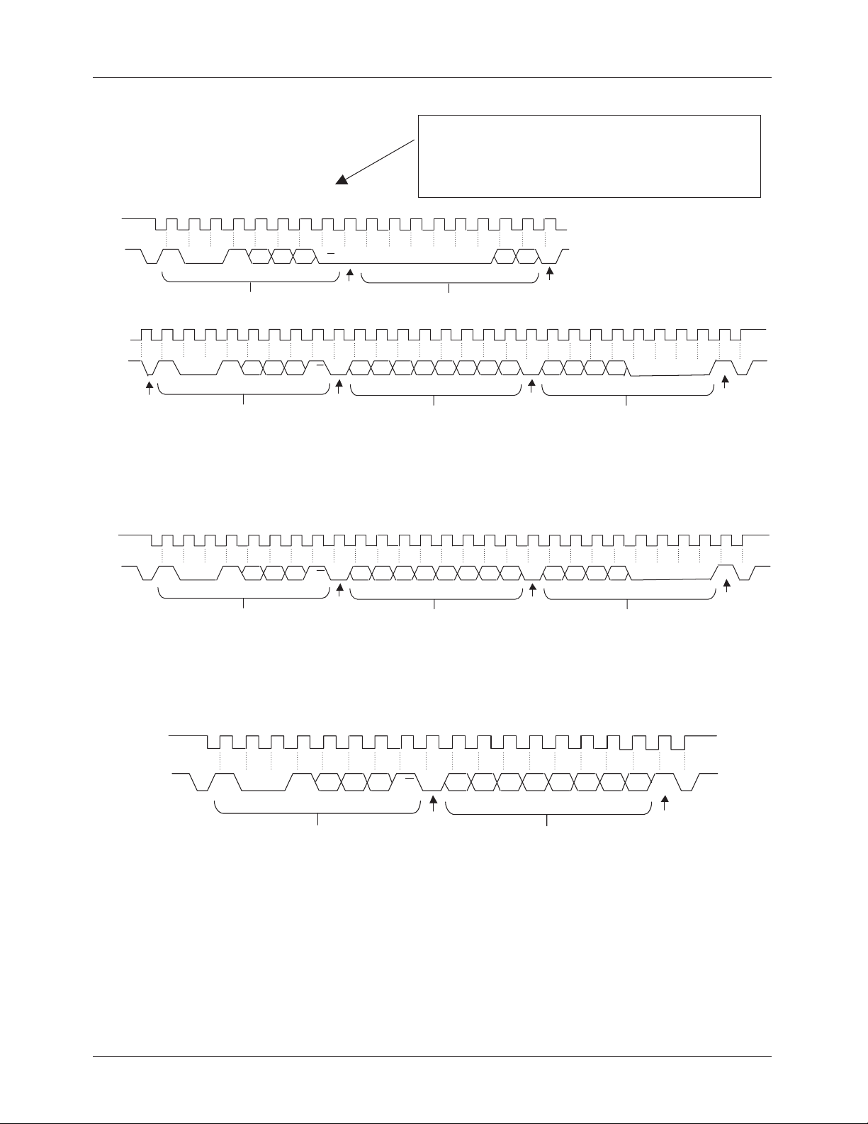
The pointer set operation is illustrated in Figure 8. Anytime a
pointer set is performed, it must be immediately followed by
a read or write operation. Note that the 6 MSBs of the
pointer value must be zero. If the 6 MSBs are not zero, the
FM75 will not send an ACK and will internally terminate the
operation. Also recall that the Command Register retains the
current pointer value between operations. Therefore, once a
register is being pointed to, subsequent read operations do
not require a pointer set cycle. Write operations always
require the pointer be reset.
) that is going to be written to
HYST
10 REV. 1.0.4 10/3/02
Page 11
PRODUCT SPECIFICATION FM75
Reading
If the pointer is already pointing to the desired register, the
master can read from that register by setting the read/write
bit (following the slave address) to a 1. After sending an
ACK, the FM75 will begin transmitting data during the
following clock cycle. If the Configuration Register is
being read, the FM75 will transmit one byte of data (see
Figure 10). The master device should respond with a NACK
followed by a stop condition. If the Temperature, T
T
Register is being read, the FM75 will transmit two
HYST
bytes of data (see Figure 9). The master must respond to the
first byte of data with an ACK and to the second byte of data
with a NACK followed by a stop condition.
To read from a register other than the one currently being
pointed to by the Command Register, a pointer set to the
desired register must be done as described previously.
Immediately following the pointer set, the master must
perform a repeat start condition (see Figures 8 and 12) which
indicates to the FM75 that a new operation is about to occur.
It is important to note that if the repeat start condition does
not occur, the FM75 will assume that a write is taking place,
and the selected register will be overwritten by the upcoming
data on the data bus. After the start condition, the master
must again send the device address and read/write bit. This
time the read/write bit must be set to 1 to indicate a read. The
rest of the read cycle is the same as described in the previous
paragraph for reading from a preset pointer location.
OS
or
Writing
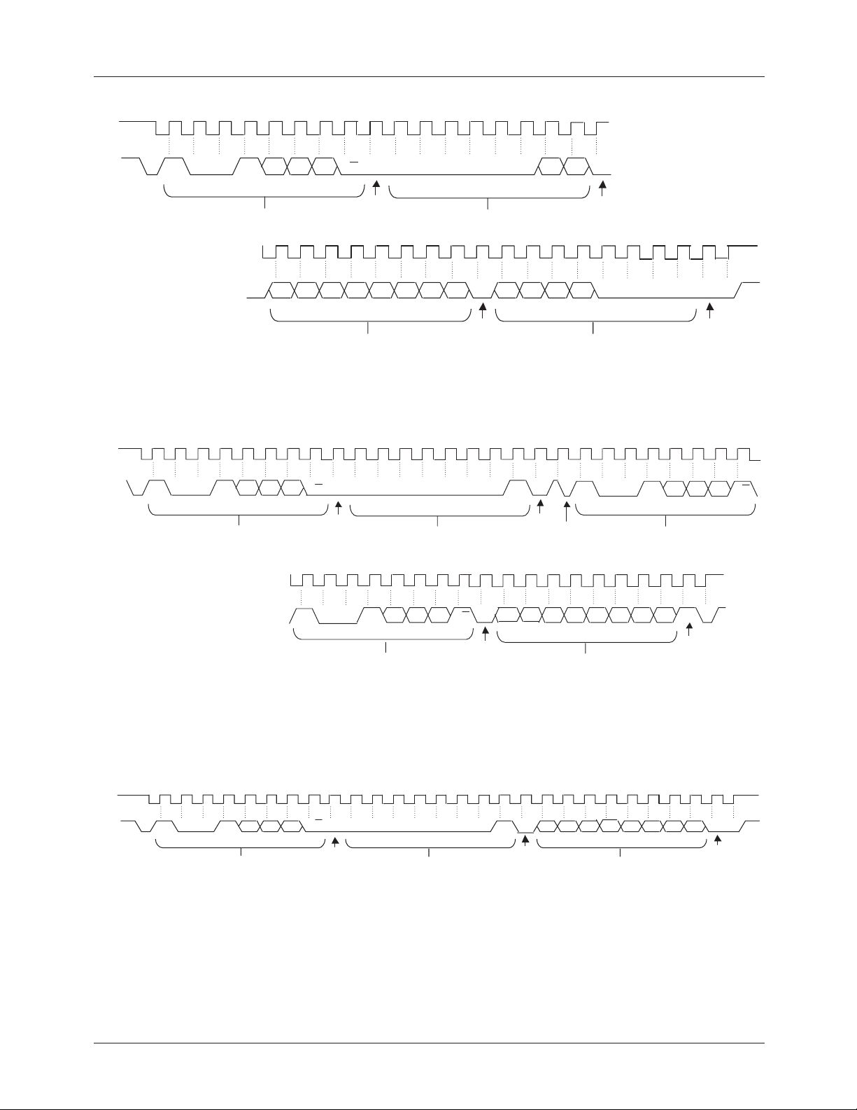
All writes must be proceeded by a pointer set as described
previously, even if the pointer is already pointing to the
desired register.
Immediately following the pointer set, the master must
begin transmitting the data to be written. If the master is
writing to the Configuration Register, one byte of data must
be sent (see Figure 13). If the T
OS
or T
HYST
Register is
being written to, the master must send two bytes of data
(see Figure 11). After transmitting each byte of data, the
master must release the SDA line for one clock to allow the
FM75 to acknowledge receiving the byte. The write
operation should be terminated by a stop signal from the
master.
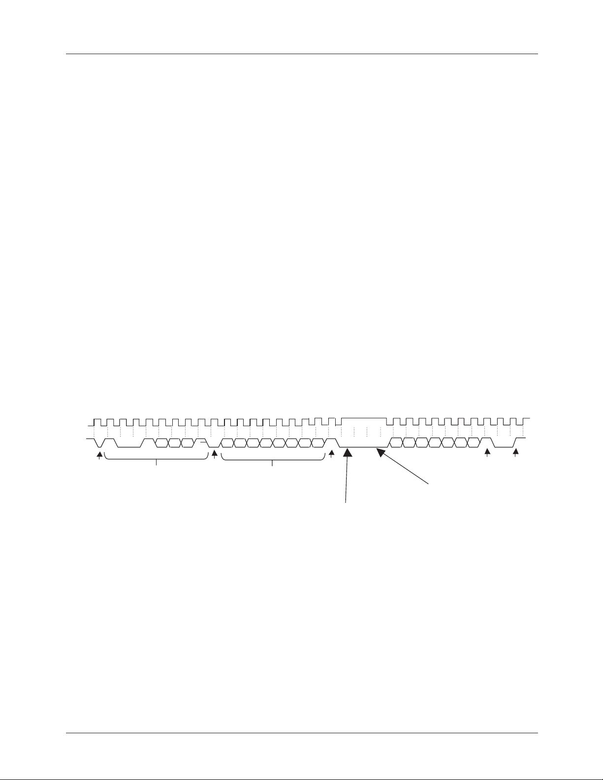
Inadvertent 8-Bit Read from a 16-Bit
Register: A Caution
An inadvertent 8-bit read from a 16-bit register, with the
D7 bit low, can cause the FM75 to pause in a state where the
SDA line is pulled low by the output data and is incapable of
receiving either a stop or a start condition from the master.
The only way to remove the FM75 from this state is to
continue clocking for 9 cycles until SDA goes high, at which
time issuing a stop condition will reset the FM75. This
sequence can be seen in Figure 7 below.
SCL
SDA
1 0 0 1 A2 A1 A0
Start
from
Master
Address Byte
Figure 7. Inadvertent 8-Bit Read from 16-Bit Register Where D7 = 0 and Forces Output Low
D7 D6 D5 D4 D3 D2 D1 D0 D7
A
R/W
Ack
from
FM75
Most Significant
Data Byte
(from FM75)
N
No Ack
from
Master
Stop intended by
Master, but FM75
SDA line locked
low
Nine additional clock cycles to reset the FM75
D6 D5 D4 D3 D2 D1 D0 N
No Ack
Condition
from
Master
Master must
Master
detect error
condition on
FM75
Stop
from
REV. 1.0.4 10/3/02 11
Page 12
FM75 PRODUCT SPECIFICATION
Note: This segment of this timing diagram is a generic
pointer set cycle which must be followed by either an
immediate read cycle or write cycle as shown in this
figure and in figures 10, 11, and 12.
SCL
SDA
SCL
. . .
SDA
. . .
S
S
Repeat
Start
from
Master
1100
110
0
A
A2 A1 A0
R/W
Address Byte Pointer Byte
A2 A1
Address Byte
R/W
A0
FM75
Ack
from
Ack
from
FM75
000
D7 D6 D5
Most Significant Data
00 0
D3 D2 D1 D0
D4
Byte
(from FM75)
P1 P0
Master
Ack
from
. . . .
A
. . . .
Ack
from
aTS75
D7 D6 D5
Least Significant Data Byte
D4
(from FM75)
Figure 8. Pointer Set Followed by Immediate Read from A 2-byte Register (Temperature, TOS or T
SCL
SDA
S PAAN
110 0 R/W
Address
Byte
D7 D6 D5 D4 D3 D2 D1 D0A2 A1 A0 D7 D6 D5 D4 0 0 0 0
Ack
from
FM75
Most Significant Data
Byte
(from FM75)
Ack
from
Master
Least Significant Data
Byte
(from FM75)
000
HYST
N
No Ack
from
Master
PAA
0
Register)
No Ack
from
Master
Figure 9. Two-byte Read from Preset Pointer Location (Temperature, T
SCL
Ack
from
FM75
X D6D5 D4 D3D2 D1D0A2 A1 A0
SDA
S PAN
110 0 R/W
Address Byte
Data Byte
OS
or T
HYST
Register)
No Ack
from
Master
(from FM75)
Figure 10. One-byte Read from Configuration Register with Preset Pointer
12 REV. 1.0.4 10/3/02
Page 13
PRODUCT SPECIFICATION FM75
A
Ack
from
FM75
. . . .
. . . .
SCL
SDA
1100
S
Address Byte
R/W
A
Ack
from
FM75
000
Pointer Byte
000
P1 P0A2 A1 A0
. . . .
A
. . . .
Figure 11. Pointer Set Followed by Immediate Write to A 2-byte Register (TOS or T
SCL
SAA
SDA
1100 R/W
Address Byte Pointer Byte
D7 D6 D5 D4 D3 D2 D1 D0 D7 D6 D5 D4 0 0 0 0
Ack
from
FM75
Least Significant Data Byte
(from Master)
Ack
from
FM75
S
1100 R/W
Repeat Start
from
Master
P0
A2 A1 A0
Most Significant Data Byte
(from Master)
000000P1
Ack
from
FM75
Register)
HYST
Address Byte
A
Ack
from
FM75
A2 A1 A0
PA
SCL
SDA
. . . .
. . . .
10
A2 A1 A0
10R/W
Address Byte
(repeated here for
clarity, transmitted only
once in the actual sequence)
Figure 12. Pointer Set Followed by Immediate Read from Configuration Register
SA A
1100
A2 A1 A0
R/W
Address Byte
Ack
from
FM75
00 0
000P1
Pointer Byte
Figure 13. Pointer Set Followed by Immediate Write to the Configuration Register
A
Ack
from
FM75
P0
XD6 D5
X
Ack
from
FM75
D4 D3 D2 D1
Data Byte
(from FM75)
D6 D5 D4 D3 D2 D1
Data Byte
(from Master)
N
No Ack
from
Master
D0
P
D0
A
Ack
from
FM75
P
REV. 1.0.4 10/3/02 13
Page 14
FM75 PRODUCT SPECIFICATION
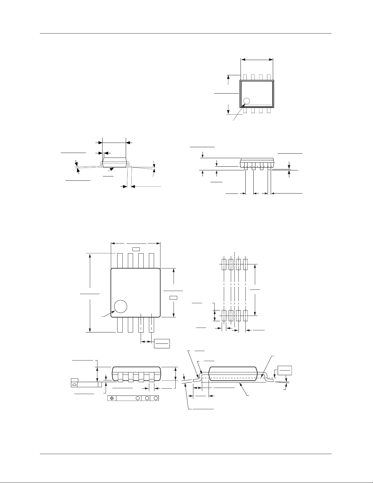
Mechanical Dimensions inches (millimeters) unless otherwise noted
0.189 - 0.197
(4.800 - 5.004)
8765
0.228 - 0.244
(5.791 - 6.198)
0.010 - 0.020
(0.254 - 0.508)
0.0075 - 0.0098
(0.190 - 0.249)
Typ. All Leads
0.193 ± 0.004
[4.9 ± 0.1]
x 45°
0.150 - 0.157
(3.810 - 3.988)
0.004
(0.102)
All lead tips
Lead #1
IDENT
0.053 - 0.069
8° Max, Typ.
(1.346 - 1.753)
All leads
0.016 - 0.050
(0.406 - 1.270)
Typ. All Leads
0.014
(0.356)
0.050
(1.270)
Typ
Molded Package, Small Outline, 0.15 Wide, 8-Lead (M8)
FS Package Number M08A
0.118 - 0.004
1234
[3 ± 0.1]
–A–
85
0.118 ± 0.004
[3 ± 0.1]
–B–
(0.040)
[1.02]
TYP
SYMM
C
(0.189)
[4.8]
0.004 - 0.010
(0.102 - 0.254)
Seating
Plane
0.014 - 0.020
(0.356 - 0.508)
Typ.
PIN 1
0.030 - 0.037
[0.78 - 0.94]
–C–
0.002 [0.05]
0.002 - 0.006
[0.06 - 0.15]
IDENT
TYP
14
0.012 ± 0.002
[0.3 ± 0.05]
0.002 [0.05]
TYP
MSACSB
(0.0256)
[0.65]
(0.033)
[0.84]
TYP
(0.016)
TYP
[0.41]
LAND PATTERN RECOMMENDATION
0.005
TYP
R
[0.13]
0.005
TYP
R
[0.13]
0.021 ± 0.005
0.0375
[0.953]
0.007 ± 0.002
[0.18 ± 0.05]
[0.53 ± 0.12]
TYP
(0.0256)
TYP
[0.65]
0°–6° TYP
SEATING PLANE
GAGE
PLANE
(0.010)
[0.23]
8-Lead Molded Mini Small Outline Package (MSOP), JEDEC MO-187, 3.0mm Wide
FS Package Number MA08D
14 REV. 1.0.4 10/3/02
Page 15

FM75 PRODUCT SPECIFICATION
Ordering Information
Part Number Package Temperature Range Shipping
FM75M8x 8-Lead SOIC -40°C to +125°C 2500 Units, Tape and Reel
FM75MM8x 8-Lead MSOP -40°C to +125°C 3000 Units, Tape and Reel
DISCLAIMER
FAIRCHILD SEMICONDUCTOR RESERVES THE RIGHT TO MAKE CHANGES WITHOUT FURTHER NOTICE TO
ANY PRODUCTS HEREIN TO IMPROVE RELIABILITY, FUNCTION OR DESIGN. FAIRCHILD DOES NOT ASSUME
ANY LIABILITY ARISING OUT OF THE APPLICATION OR USE OF ANY PRODUCT OR CIRCUIT DESCRIBED HEREIN;
NEITHER DOES IT CONVEY ANY LICENSE UNDER ITS PATENT RIGHTS, NOR THE RIGHTS OF OTHERS.
LIFE SUPPORT POLICY
FAIRCHILD’S PRODUCTS ARE NOT AUTHORIZED FOR USE AS CRITICAL COMPONENTS IN LIFE SUPPORT DEVICES
OR SYSTEMS WITHOUT THE EXPRESS WRITTEN APPROVAL OF THE PRESIDENT OF FAIRCHILD SEMICONDUCTOR
CORPORATION. As used herein:
1. Life support devices or systems are devices or systems
which, (a) are intended for surgical implant into the body,
or (b) support or sustain life, and (c) whose failure to
perform when properly used in accordance with
2. A critical component in any component of a life support
device or system whose failure to perform can be
reasonably expected to cause the failure of the life support
device or system, or to affect its safety or effectiveness.
instructions for use provided in the labeling, can be
reasonably expected to result in a significant injury of the
user.
www.fairchildsemi.com
10/3/02 0.0m 003
2002 Fairchild Semiconductor Corporation
Stock#DS30000075
 Loading...