

Page 1
Data Sheet
Conexant
Doc. No. 100086B
Proprietary Infor m at ion February 18, 2000
FM336
V.34/Group 3 High Performance Fax Modem Family
The Conexant™ FM336 High Performance Fax Modem f am ily of f er s I TU-T
V.34 half-duplex mode operation that supports synchronous Group 3 facsimile
send and receive speeds up to 33600 bits per second (bps). The FM 336- D and
FM336-D90 support ITU-T V.34 duplex data and synchr onous/asynchronous
modes with rates up to 33600 bps. The FM 336- D90 also support s I TU-T V. 90
PCM mode, which can receive data at speeds up to 56 Kbps.
The device has low voltage operation and is housed in a 100-pin Plastic Quad
Flat Package (PQFP). The modem’s small size and low power consumption
allow the design of compact system enclosures for use in industrial, of f ice, and
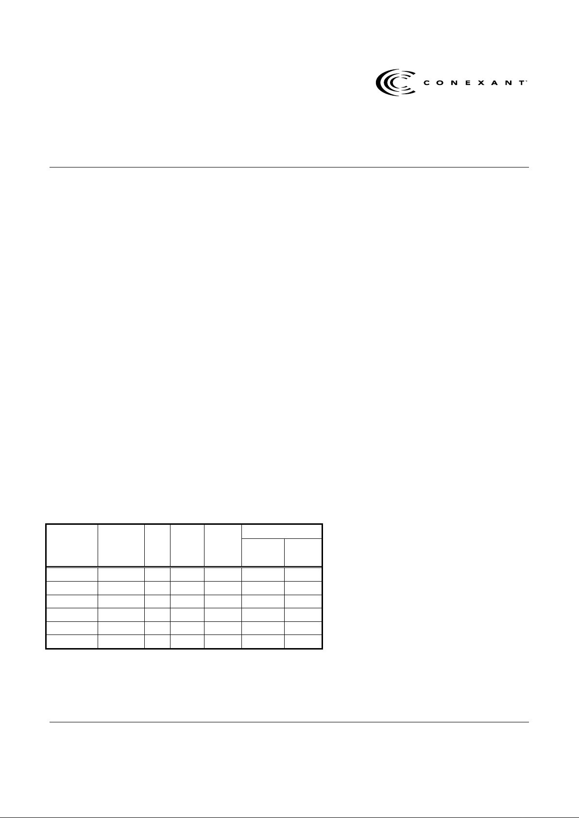
home environments. Table 1 lists the FM 336 M odem Fam ily models and
features.
This data sheet is for the FM336 f amily of modems, which includes all of the
features of the FM 336 ver s ion, t he duplex dat a m ode opt ion, and t he V. 90
PCM mode option. For more inf or m at ion on t hese f eat ur es, refer to the FM 336
High Performance Fax Modem Designer's Guide, t he FM 336- D V.34/Group 3
High Performance Fax Modem with Duplex Data Modes Supplement, and t he
FM336-D90 V.34/Group 3 High Perfor m ance Fax Modem with V.90 PCM
Mode Supplement.
Utilizing V.34 and V.90 t echniques t o opt im iz e m odem c onf iguration for line
conditions, the modem connects at t he optimal selected data rate that t he
channel can support from 2400 bps up to 56000 bps. The modem can operate
over the Public Switched Telephone Network (PSTN) through a line terminator
provided by a Data Access Arrangement (DAA).
Table 1. FM336 Modem Fam i ly Models and Features
InputModem
Model
Part
Number
V.34
Fax
Data
Mode
(–D)
V.90
PCM
Mode
(-D90)
Oscillator
Clock
Crystal
Clock
FM336 R6719-11 Yes No No Yes No
FM336 R6719-12 Yes No No No Yes
FM336-D R6719-13 Yes Yes No Yes No
FM336-D R6719-14 Yes Yes No No Yes
FM336-D90 R6719-15 Yes Yes Yes Yes No
FM336-D90 R6719-16 Yes Yes Yes No Yes
Features (Entire FM336 Family)
• 2-wire half-duplex fax modem modes
with send and receive data rates up to
33600 bps
− V.34 half-duplex, V.17, V.29,
V.27 ter, and V.21 channel 2
− Short train option in V.17 and V.27 ter
• 2-wire duplex data modem modes
− V.21, V.23 (75 bps TX/1200 bps RX
or 1200 bps TX/75 bps RX)
• PSTN session starting
− V.8 signaling
• HDLC support at all speeds
− Flag generation, 0-bit stuffing, ITU
CRC-16 or CRC- 3 2 c a lc ula tion and
generation
− Flag detection, 0 bit deletion, ITU
CRC-16 or CRC- 3 2 c h ec k s u m error
detection
− FSK flag pattern detection during
high-speed receiving
• Tone modes and features
− Programmable single or dual tone
generation
− DTMF receiver
− Tone detection with three
programmable tone detect or s
• Serial synchronous data
• Parallel synchronous data
• Automatic Rate Adaptation (ARA) in
V.34 half-duplex
• Auto-dial and auto-answer control
• TTL and CMOS compatible DTE
interface
− ITU-T V.24 (EIA/TI A-232- E)
(data/control)
− Microprocessor bus
(data/configuration/control)
• Receive dynamic range:
− 0 dBm to –43 dBm for V.17, V. 29,
V.27 ter and V.21
− –9 dBm to –43 dBm for V.34 half-
duplex
Page 2

FM336 V.34/Group 3 High Perform ance Fax M odem Fam ily
2
Conexant
100086B
Features (Entire FM336 Family − Continued)
•
Programmable RLSD turn-on and tur n- of f thresholds
•
Programmable transmit level: 0 t o –15 dBm
•
Adjustable speaker output to monitor r eceived signal
•
DMA support for interr upt lines
•
Two 16-byte FIFO data buf f er s for burst data tr ansf er with extension
up to 255 bytes
•
NRZI encoding/decoding
•
Diagnostic capability
•
+3.3 V operation with +5 V tolerant inputs
•
+5 V analog signal interface
•
100-pin PQFP package
•
Typical power consumption
−
Sleep mode: 20 mW
−
Normal mode: 250 mW
Distinguishing Features (-D / -D90 )
•
2-wire duplex data modem modes with send and receive rat es up t o
33600 bps
−
V.34 (33.6 Kbps), V.32 bis, V. 32, V. 22 bis, and V. 22
−
Bell 212A and 103
•
Serial asynchronous data
•
Parallel asynchronous data
•
In-band secondary channel (V.34 and V.32 bis)
•
Automatic Rate Adaptation (ARA) in V.34 duplex and V.32 bis
•
Automatic Mode Selection (AMS)
•
Digital near-end and far-end echo cancellation
•
Bulk delay fo r satellite transmis s io n
•
Receive dynamic range:
−
–9 dBm to –43 dBm for V.34, V. 32 bis, V. 32, V. 22 bis, V. 22, V. 23
•
511 pattern generation/ det ect ion
•
V.13 signaling
•
Diagnostic capability
−
V.54 inter-DCE signaling
−
V.54 local analog and remote digital loopback
Distinguishing Features
(-D90 only)
•
2-wire duplex data modem modes with
receive data rates up to 56 Kbps and
send data rates as specified in the V.34
specification
−
V.90 PCM mode
Copyright © 2000, Conexant Systems, Inc., All Rights Reserved.
Information in this document is provided in connection with Conexant Systems, Inc. ("Conexant") products. These materials are provided by
Conexant as a service to its customers and may be used for informational purposes only. Conexant assumes no responsibility for errors or
omissions in these materials. Conexant may make changes to specifications and product descriptions at any time, without notice. Conexant
makes no commitment to update the information contained herein. Conexant shall have no responsibility whatsoever for conflicts or
incompatibilities arising from future changes to its specifications and product descriptions.
No license, express or implied, by estoppel or otherwise, to any intellectual property rights is granted by this document. Except as provided in
Conexant’s Terms and Conditions of Sale for such products, Conexant assumes no liability whatsoever.
THESE MATERIALS ARE PROVIDED "AS IS" WITHOUT WARRANTY OF ANY KIND, EITHER EXPRESS OR IMPLIED, RELATING TO SALE
AND/OR USE OF CONEXANT PRODUCTS INCLUDING LIABILITY OR WARRANTIES RELATING TO FITNESS FOR A PARTICULAR
PURPOSE, MERCHANT A B ILITY, OR INF RINGEMENT OF ANY PA TENT, COPYRIGHT OR OTHE R INTELLECTUAL PROPERTY RIGHT.
Conexant further does not warrant the accuracy or completeness of the information, text, graphics or other items contained within these
materials. Conexant shall not be liable for any special, indirect, incidental, or consequential damages, including without limitation, lost revenues or
lost profits, which may result from the use of these materials.
Conexant products are not intended for use in medical, life saving or life sustaining applications. Conexant customers using or selling Conexant
products for use in such applications do so at their own risk and agree to fully indemnify Conexant for any damages resulting from such improper
use or sale.
The following are trademarks of Conexant Systems, Inc.: Conexant, the Conexant C symbol, and “What’s Next in Communications
Technologies.” Product names or services listed in this publication are for identification purposes only, and may be trademarks of third parties.
Third-party brands and names are the property of their respective owners.
Reader Response:
Conexant strives to produce quality documentat ion and welcomes your f eedback. Please send
comments and suggestions to conexant.tech.pubs@conexant.com. For technical questions, contact your local Conexant
sales office or field applications engineer.
Page 3

V.34/Group 3 High Perform ance Fax M odem Fam ily FM336
100086B
Conexant
3
Group3 Facsimile Modem
(Entire FM336 Family)
The modem satisfies the requirement s s pec ified in
ITU-T rec om mendations V.34 half- duplex , V.17, V.29,
V.27 ter, V .21, and meets the binary signaling
requirements of V .8 and T.30 with Annex F.
Internal HDLC support elim inates the need for an
external serial input/output (SIO) device in the DTE for
products incorporating error detect ion and T.30
protocol. The m odem c an perform HDLC framing per
T.30 at all data s peeds . CRC generation/check ing
along with zero insertion/deletion enhances
SDLC/HDLC frame operations. An FSK flag pattern
detector fac ilitates FSK det ection during high-speed
reception. The m odem features a programm able
DTMF trans m itter/receiv er and three programmable
tone detectors .
Duplex Data Mode (-D / -D90)
The duplex data mode supports Internet facsimile
applications. The m odem c an c onnect at the highest
data rate up to 33600 bps with auto fall back to
V.32 bis. The FM336-D and FM336-D90 modem
satisfies t he r equir em ents specified in ITU-T
recommendations V.34, V.32 bis, V .32, V.22 bis, V .22,
V.23, V.21, Bell 212A, and Bell 103.
ITU-T V.90 PCM Mode (-D90)
The ITU-T V .90 PCM mode can receive data at
speeds up to 56
Kbps
from a digitally connec ted V.90
central site modem . The FM336-D90 t ak es adv antage
of the PSTN whic h is pr im ar y to the central office local
loop and is ideal for applications s uc h as r em ote
access to an Internet Service Pr ov ider (ISP), online
service, or cor porate intranet. The modem can send
upstream data at s peeds up to V.34 rate.
Page 4

FM336 V.34/Group 3 High Perform ance Fax M odem Fam ily
4
Conexant
100086B
Technical Specifications
The single device modem provides the processing
core for a complet e facsimile modem design.
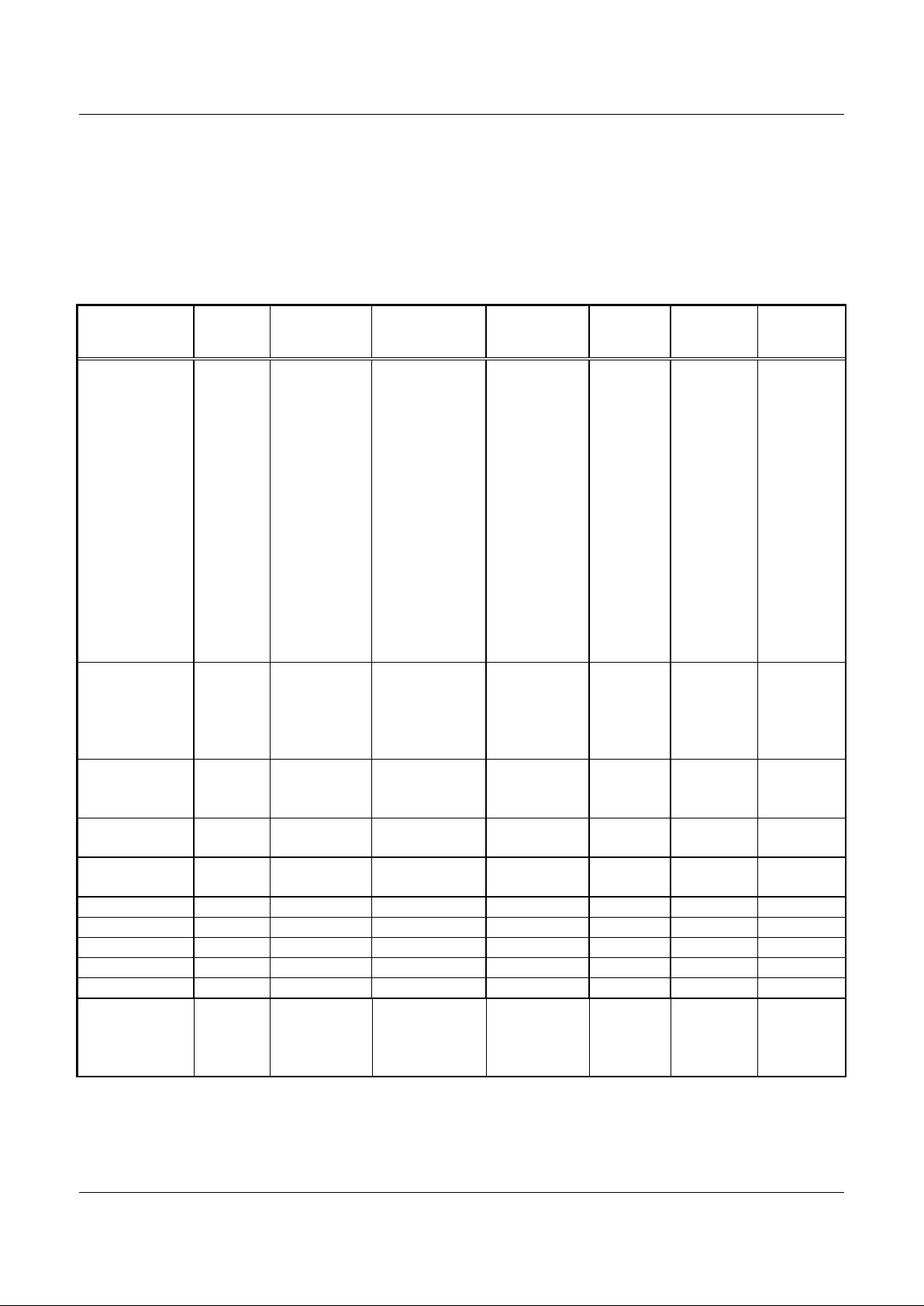
Configurations and Rates
The selectable modem c onfigurations, signaling r ates,
and data rates are listed in Table 2.
Automatic Mode Selection (-D / -D90)
When Automatic M ode S elec tion (AMS) is enabled,
the modem configures itself to the highest compatible
data rate support ed by the remote modem. A utomode
operation is supported in V .90 (-D90 only), V.34,
V.32 bis, V. 32, V.22 bis, V. 22, V.21, V. 23, Bell 212A,
and Bell 103 modes.
Automatic Rate Adaptation
In V.34 duplex, V .34 half-duplex, and V. 32 bis modes,
Automatic Rat e A daptation (ARA) can be enabled to
select the optim al highes t acceptable data rate based
on the Eye Quality M onitor (EQM). This selection
occurs during star tup.
Two ARA modes are available. ARA in ROM is an
adaptive selection made by the modem based upon a
fixed ROM table. ARA in RAM is based on the hos t
programmable RAM table and c an be changed by the
user.
Data Encoding (-D / -D90)
The data encoding confor m s to ITU-T
recommendations V.90 (-D90 only), V.34, V.32 bis,
V.32, V.17, V.29, V.27 ter, V.22 bis, V.22, V.23, or
V.21, and is compatible with Bell 208, 212A, or 103,
depending on the configuration.
Tone Generation and Supervisory Tone Detection
The modem can generate s ingle or dual voice-band
tones from 0 Hz to 3600 Hz with a resolution of
0.15 Hz and an accuracy of ± 0.01%. T ones ov er
3000 Hz are attenuated. DTMF tone gener ation allows
the modem to operat e as a pr ogrammable DTMF
dialer.
Three parallel tone detec tors (A, B, and C) are
provided for supervi s or y tone detection. T he s ignal
path to these det ec tors is separate from the main
received signal path.
Each tone detect or c ons is ts of two casc aded s ec ond
order IIR biquad filters. The coefficients are host
programmable. Each fourth order filter is followed by a
level detector which has hos t programmable turn- on
and turn-off thresholds allowing hysteres is . A pre-filter
and squarer precede tone det ec tor C. This cir c uit is
useful for detec ting a tone with a frequenc y equal to
the difference between two tones that may be
simultaneously present on the line. The squar er m ay
be disabled by the SQDI S bit causing tone detect or C
to be an eight-order f ilter. The tone detectors are
disabled in data mode.
The tone detect ion s am ple r ate is 9600 Hz in V.8 and
V.34 modes and is 7200 Hz in non-V .34 modes. The
default call progress filter coeff ic ients are based on a
7200 Hz sampling rate and apply t o non- V .34 modes
only. The maximum detection bandwidth is equal t o
one-half the sample rate.
Auto-Dialing and Auto-Answering Control
Features are prov ided to allow the host to per form
auto-dialing and auto-answering. These funct ions
include DTMF or pulse dialing, ring detection, and a
comprehensive superv is or y tone detection scheme.
The major control par ameters are host pr ogr am m able.
Transmitted Data Spectrum
The transmit ter spectrum is s haped by r ais ed c os ine
filter functions, either the square root of 12.5% ( V .34,
V.32 bis, V. 32) , 20% (V.17 and V.29) , 50% (V.27 ter,
Bell 208), or 75% (V. 22 bis , Bell 212A).
Transmit L evel
The transmit ter output level is selectable from 0 dBm
to –15 dBm in 1-dB steps and is accur ate to ±0.5 dB
when used with an external hybr id. The output level
can also be tuned by changing a gain constant in the
modem DSP RAM. The maximum V.34 transmit level
for acceptable rec eiv e per formance should not exc eed
–9 dBm.
Answer Tone (-D / -D90)
When the NV25 bit is a z er o, the modem generates a
2100 Hz answer tone at t he beginning of the answer
handshake for 5.0 sec onds (V.8) or 3.6 sec onds ( V .32
bis, V.32, V .22 bis, V.22, V .23, and V.21). The answer
tone has 180° phase revers als ev er y 0.45 seconds to
disable network echo canceller s (V.8, V.32 bis , V.32).
Receive Level
The modem satisfies performance r equir em ents for
received line signal levels fr om 0 dB m to –43 dBm
measured at the receiver analog (TIP and RING)
input in V.17, V.29, V.27 ter, and DTMF modes. In
V.90, V.34, V.32 bis, V. 32, V.22 bis, V.22, and V.23
modes, the receiv e lev el r ange is from –9 dBm
(–15 dBm at RIN) to –43 dBm .
Page 5
V.34/Group 3 High Perform ance Fax M odem Fam ily FM336
100086B
Conexant
5
Carrier Recovery
The carrier recovery circuit can track a ±7 Hz
frequency off s et in the received carr ier .
Echo Canceller (-D / -D90)
A data echo canceller wit h near - end and far-end echo
cancellation is included for 2- wir e duplex
V.90/V.34/V.32 bis/V. 32 oper ation. The combined
echo span of near and far c anc ellers can be up to
40 ms. The proportion allotted to each end is
automatically det er m ined by the modem. The delay
between near-end and far-end ec hoes can be up to
1.2 seconds.
Table 2. Configurat ions, Signaling Rat es, and Dat a Rat es
Configuration Modulation Carrier
Frequency (Hz)
±0.01%
Data Rate (bps)
±0.01%
Symbol Rate
(Symbols/Sec.)
Bits/Symbol
Data
Bits/Symbol
TCM
Constellation
Points
V.90 PCM PCM — 56000 R/V.34 rates T
(Note 4)
8000 Dynamic ——
V.34 33600 TCM** TCM Note 2 33600 3429 only Note 2 Note 2 Note 2
V.34 31200 TCM** TCM Note 2 31200 3200 min Note 2 Note 2 Note 2
V.34 28800 TCM** TCM Note 2 28800 3000 min Note 2 Note 2 Note 2
V.34 26400 TCM** TCM Note 2 26400 2800 min Note 2 Note 2 Note 2
V.34 24000 TCM** TCM Note 2 24000 2800 min Note 2 Note 2 Note 2
V.34 21600 TCM** TCM Note 2 21600 2400 min Note 2 Note 2 Note 2
V.34 19200 TCM** TCM Note 2 19200 Note 2 Note 2 Note 2 Note 2
V.34 16800 TCM** TCM Note 2 16800 Note 2 Note 2 Note 2 Note 2
V.34 14400 TCM** TCM Note 2 14400 Note 2 Note 2 Note 2 Note 2
V.34 12000 TCM** TCM Note 2 12000 Note 2 Note 2 Note 2 Note 2
V.34 9600 TCM** TCM Note 2 9600 Note 2 Note 2 Note 2 Note 2
V.34 7200 TCM** TCM Note 2 7200 Note 2 Note 2 Note 2 Note 2
V.34 4800 TCM** TCM Note 2 4800 Note 2 Note 2 Note 2 Note 2
V.34 2400 TCM** TCM Note 2 2400 2400 only Note 2 Note 2 Note 2
V.32 bis 14400 TCM TCM 1800 14400 2400 6 1 128
V.32 bis 12000 TCM TCM 1800 12000 2400 5 1 64
V.32 bis 9600 TCM TCM 1800 9600 2400 4 1 32
V.32 bis 7200 TCM TCM 1800 7200 2400 3 1 16
V.32 bis 4800 QAM 1800 4800 2400 2 0 4
V.32 9600 TCM TCM 1800 9600 2400 4 1 32
V.32 9600 QAM 1800 9600 2400 4 0 16
V.32 4800 QAM 1800 4800 2400 2 0 4
V.22bis 2400 QAM 1200/2400 2400 600 4 0 16
V.22bis 1200 DPSK 1200/2400 1200 600 2 0 4
V.22 1200 DPSK 1200/2400 1200 600 2 0 4
V.22 600 DPSK 1200/2400 600 600 1 0 4
V.23 1200/75 FSK 1700/420 1200/75 1200 1 0 —
V.21 FSK 1080/1750 Up to 300 300 1 0 —
Bell 208 4800 DPSK 1800 4800 1600 3 0 8
Bell 212A DPSK 1200/2400 1200 600 2 0 4
Bell 103 FSK 1170/2125 Up to 300 300 1 0 —
V.17 14400 TCM TCM 1800 14400 2400 6 1 128
V.17 12000 TCM TCM 1800 12000 2400 5 1 64
V.17 9600 TCM TCM 1800 9600 2400 4 1 32
V.17 7200 TCM TCM 1800 7200 2400 3 1 16
Page 6

FM336 V.34/Group 3 High Perform ance Fax M odem Fam ily
6
Conexant
100086B
Table 2. Configurat i ons, Signaling Rates, and Dat a Rates (Cont'd)
Configuration Modulation Carrier
Frequency (Hz)
±0.01%
Data Rate (bps)
±0.01%
Symbol Rate
(Symbols/Sec.)
Bits/Symbol
Data
Bits/Symbol
TCM
Constellation
Points
V.29 9600 QAM 1700 9600 2400 4 0 16
V.29 7200 QAM 1700 7200 2400 3 0 8
V.29 4800 QAM 1700 4800 2400 2 0 4
V.27 ter 4800 DPSK 1800 4800 1600 3 0 8
V.27 ter 2400 DPSK 1800 2400 1200 2 0 4
V.21 Channel 2 FSK 1750 300 300 1 0 —
Notes:
1. Modulation legend: TCM: Trellis-Coded Modulation
QAM: Quadrature Amplitude Modulation
PCM: Pulse Coded Modulation
FSK: Frequency Shift Keying
DPSK: Differential Phase Shift Keying
2. Adaptive; established during handshake:
Symbol Rate (Baud) V.34 Low Car rier Frequency (Hz) V.34 High Carrier Frequency (Hz)
2400 1600 1800
2800 1680 1867
3000 1800 2000
3200 1829 1920
3429 1959 1959
3. ** For both duplex and half-duplex modes.
4. Maximum data rate.
Page 7

V.34/Group 3 High Perform ance Fax M odem Fam ily FM336
100086B
Conexant
7
Data Formats
Serial Synchronous Data
•
Data rate: 300-56000 bps ( -D90) or
300-33600 bps ±0.01%
•
Selectable clock: Internal, ext er nal, or slave
Serial Asynchronous Data (-D / -D90)
•
Data rate: 300-56000 bps ( -D90) or 300-33600
bps +1%/-2. 5% or +2.3%/-2.5%; up to 300 bps
(V.21 and Bell 103); 1200/75 bps (V.23)
•
Data bits per charac ter: 7, 8, 9, 10, or 11
Parallel Synchronous Data
•
Normal sync: 8-bit data for transmit and receive
•
Data rate: 300-56000 bps ( -D90) or 300-33600
bps ±0.01%
•
SDLC/HDLC support: Transmitter : Flag
generation, 0-bit s tuffing, CRC-16 or
CRC-32 generation
•
Receiver: Flag det ec tion, 0-bit deletion, CRC-16
or CRC-32 checking
Parallel Asynchronous Data (-D / -D90)
•
Data rate: 300-56000 bps ( -D90) or 300-33600
bps +1%/-2. 5% or +2.3%/-2.5%; 1200, 300, or 75
bps (FSK)
•
Data bits per charac ter: 5, 6, 7, or 8
•
Parity generation/checking: Odd, Even,
or 9th data bit
Async/Sync an d Sync/Async Conversion
(-D / -D90)
An asynchronous-t o- s ynchronous converter is
provided in the transm i tter and a synchronous- toasynchronous converter is provided in the rec eiv er .
The converters oper ate in both serial and parallel
modes. The async hr onous character form at is 1 start
bit, 5 to 8 data bits, an optional parity bit, and 1 or 2
stop bits. V alid c har ac ter size, including all bit s , is 7, 8,
9, 10, or 11 bits per c har ac ter. Two ranges of signaling
rates are provided:
•
Basic range: + 1% to –2.5%
•
Extended overspeed range: +2.3% to –2.5%
When the transm it converter is oper ating at the basic
signaling rate, no more than one stop bit will be
deleted per 8 consecutiv e c har ac ters. When operating
at the extended rate, no more than one st op bit will be
deleted per 4 consecutiv e c har ac ters. Break handling
is performed as desc r ibed in V.14.
Asynchronous characters are accept ed on the TXD
serial input and are issued on t he RX D serial output.
V.54 Inter-DCE Signaling (-D / -D90)
The modem supports V .54 inter-DCE signaling
procedures in synchr onous and as y nc hr onous
configurations. Transmission and detec tion of the
preparatory, ac k nowledgment, and termination phases
as defined in V.54 are prov ided. Three control bits
(V54T, V54A, and V54P) in the transmitter allow the
host to send the appr opr iate bit patterns . Three control
bits (V54TE, V54AE, and V54PE) in the receiver are
used to enable one of three bit pattern detec tors. A
status bit ( V 54DT) indicates when the s elec ted pattern
detector has f ound the corresponding bit pat tern.
V.13 Remote RTS Signaling (-D / -D90)
The modem supports V .13 remote RTS s ignaling.
Transmission and det ection of signaling bit pat terns in
response to a change of s tate in the RTS bit or the
/RTS input signal ar e pr ovided. This feat ur e m ay be
used to clamp/unclam p the local /RLSD and RXD
signals in response to a change in the remote /RT S
signal in order to simulat e controlled carrier operation
in a constant carr ier environment. The m odem
automatically clam ps and unc lamps /RLSD.
In-Band Secondary Channel (-D / -D90)
A duplex in-band secondary channel is pr ov ided in
V.34 (all speeds) and V.32 bis/V.32 (7200 bps and
above) modes. The s ec ondary channel operates in
parallel data mode with independent transmit and
receive interrupt s and data buffers. The main channel
may operate in parallel or ser ial mode.
In V.34 modes, the secondary channel rat e is 200 bps .
In V.32 bis/V .32 modes, the secondary channel rate is
150 bps. This rat e is als o hos t programmable in V.32
bis/V.32 modes.
Page 8

FM336 V.34/Group 3 High Perform ance Fax M odem Fam ily
8
Conexant
100086B
Transmit an d Receive FIFO Data Buffers
Two 16-byte first-in first-out (FIFO) data buffers allow
the DTE/host to output up to 16 by tes of transm it data
to the transm itter FIFO (TXFIFO) and input up to
16 bytes of accum ulated received data fr om the
receiver FIFO (RXFIFO). The TXFIFO and RX FIFO
can be extended up to 255 byt es . The size of F IFO
extension is 255 bytes ov er all and c an be divided
between the two FIFOs in any propor tion.
The RXFIF O is always enabled. The host can enable
the TXFI FO. Stat us bits indicate when the TXFIFO is
not full, the TXFIFO is half-full (eight or mor e by tes
loaded), the RXFIFO is empty , and the RXFIFO is
half-full. An interrupt mask regis ter allows an interrupt
request to be generat ed whenev er the status bits
change state.
DMA Support for Interrupt Request Lines
DMA support is available in s y nc hr onous data modes.
When DMA support is enabled, the modem /RI and
/DSR lines are assigned t o Transmitter Reques t
(TXRQ) and Receiv er Reques t (RXRQ) hardware
output interrupt request lines, res pec tively. The T X RQ
and RXRQ signals follow t he as s er tion of the Trans m it
Data Buffer E m pty (TDBE) and Receiv e Data Buffer
Full (RDBF) int er r upt bits, thereby allowing the
DTE/host to respond immediately t o the interrupt
request without m as k ing out status bit s to determine
the interrupt s our c e.
Caller ID Demodulation
Caller ID informat ion c an be demodulated in V.23
1200 receive configurat ion and pr es ented to the
DTE/host in s er ial ( RX D) or parallel (RBUFFER) form.
Telephone Line Interface
Line Transformer Interface.
V.34 places high
requirements upon the Data Access Arr angem ent
(DAA) correction to the telephone line. Due to the
wider bandwidth requirement at a symbol rate of
3429 symbols/second, the DAA must m aintain linearity
from 150 Hz to 3950 Hz.
Relay Contro l.
Direct control of the off-hook and
talk/data relay s is pr ov ided. Internal relay dr iv er s allow
direct connection to the off-hook and talk/data relays.
The talk/dat a r elay output can optionally be used for
pulse dial.
Speaker Interf ace.
A SPKR output is provided with
on/off and volume c ontrol logic incorporated in t he
modem, requiring only an external amplifier to dr iv e a
speaker.
Hardware Int erf ace S ignals
Functional interface signals are shown in Figur e 1. In
this diagram, an active low signal is indicated by a
forward slash “/” (/ RESET ). A clock intended to
activate logic on it s r is ing edge (low-to-high transition)
is called active high (T DCLK ) , while a clock intended
to activate logic on its falling edge (high-to-low
transition) is c alled ac tive low (/RDCLK).
Modem pin assignments are shown in Figure 2. Signal
descriptions are listed in Table 3.
Power and M aximum Rating s
Current and power requirements are listed in Table 4.
Absolute maximum r atings are listed in Table 5.
Clock Sou rces
The modem is off er ed in two configurations depending
upon the selected clock s our ce. One configuration
utilizes a crystal source and the other us es an
oscillator source.
For the crys tal configuration, the crystal is connec ted
to XTLI (pin 85) and X TLO (pin 86). F or the oscillator
source, the osc illator is connected to CLK IN (pin 85)
and XTLO (pin 86) is not connected.
Package Dimensi ons
The package dimensions are s hown in Figure 3.
Additional Information
Additional design information is described in
the
FM336 V.34/Group3 High Performanc e Fax Modem
Designer’s Guide
(Doc. No. 100522A),
FM336–D
V.34/Group3 High P er formance FAX M odem with
Duplex Data Modes Supplement to the Designer’s
Guide
(Doc. No. 100523A), and
FM336–D90
V.34/Group3 High P er formance FAX M odem with
V.90 PCM Modes Supplem ent to the Designer’s Guide
(Doc. No. 100502A).
Page 9

V.34/Group 3 High Perform ance Fax M odem Fam ily FM336
100086B
Conexant
9
V.24
Interface
Host
Processor
FM336
Modem Family
Crystal
Power Supply
Speaker
Amplifier
Optional
Eye Pattern
Generator
Line
Interface
/RTS
TXD
/CTS
TDCLK
XTCLK
/RLSD
RXD
/RDCLK
/DTR
/RI*
/DSR**
/RD
/CS
/WR
D[7:0]
RS[4:0]
IRQ
/RESET
TXRQ*
RXRQ**
XTL0
XTLI
TXA1
RIN
OH
TXA2
/TALK
RINGD
EYEXY
EYESYNC
EYECLK
+5V
AGND
DGND
SPKR
* Selectable; TXRQ output replaces /RI output.
** Selectable; RXRQ output replaces /DSR output.
100501A F 1
TIP
RING
telephone
line
+3.3V
Oscillator
CLKIN
OR
Figure 1. Functional Interface Si gnal s
Page 10

FM336 V.34/Group 3 High Perform ance Fax M odem Fam ily
10
Conexant
100086B
1
2
3
4
5
6
7
8
9
10
11
12
13
14
15
16
17
18
19
20
21
22
23
24
25
26
27
28
29
30
80
79
78
77
76
75
74
73
72
71
70
69
68
67
66
65
64
63
62
61
60
59
58
57
56
55
54
53
52
51
VSS
IRQ
/RTS
RINGD
/RI
/DSR
EYEXY
XCLK
YCLK
VGG
IA_SLEEP
VDD1
/DTR
RXD
RESERVED
VSS
XTCLK
VDD1
VCORE
SR1IO
NC
RESERVED
RESERVED
VDD1
SLEEP
NC
NC
VSS
VSUB
RESERVED
RESERVED
RS2
RS3
RS4
/CS
/WR
/RD
/RDCLK
/RLSD
TDCLK
TXD
/CTS
VDD1
RESERVED
RESERVED
VSS
NC
/RESET
SR4OUT
NC
SR4IN
CLK_OUT
EYESYNC
EYECLK
MAVSS
MAVDD
SPKR
TXA2
TXA1
VREF
PLL_GND
VSS
PLL_VDD
RS1
RS0
D7 D6D5
VDD1D4D3D2D1D0XTALO
XTALI/CLKIN
VDD1
RESERVED
RESERVED
GPO0
VC
RIN
MAVSS
/POR
RESERVED
RESERVED
/TALK
VDD
RESERVED
RESERVED
NC
M_CNTRL_SIN
M_CLKIN
M_TXSIN
M_SCK
M_RXOUT
M-STROBE
RESERVED
OH
VDD
31
32
33
34
35
36
37
38
39
40
41
42
43
44
45
46
47
48
49
50
100
99
98
97
96
95
94
93
92
91
90
89
88
87
86
85
84
83
82
81
1176DG F2-2
Figure 2. FM336 Fami ly Modem Pin Assignments - 100-Pin PQFP
Page 11

V.34/Group 3 High Perform ance Fax M odem Fam ily FM336
100086B
Conexant
11
Table 3. Signal Descri pt i ons
Pin Signal Label I/O
Type
1
Interface
3 Pin Signal Label I/O
Type
1
Interface
3
1 RESERVED —— 51 RESERVED ——
2 RS2 IA HOST Interface 52 VSUB GND —
3 RS3 IA HOST Interface 53 VSS GND —
4 RS4 IA HOST Interface 54 NC — NC
5 /CS IA HOST Interface 55 NC — NC
6 /WR IA HOST Interface 56 SLEEP MI Modem Interconnect
7 /RD IA HOST Interface 57 VDD1 PWR —
8 /RDCLK OA DTE Serial Interface 58 RESERVED ——
9 /RLSD OA DTE Serial Interface 59 RESERVED ——
10 TDCLK OA DTE Serial Interface 60 NC — NC
11 TXD IA DTE Serial Interface 61 SR1IO MI Modem Interconnect
12 /CTS OA DTE Serial Interface 62 VCORE PWR —
13 VDD1 PWR — 63 VDD1 PWR —
14 RESERVED —— 64 XTCLK IA DTE Serial Interface
15 RESERVED —— 65 VSS GND —
16 VSS GND — 66 RESERVED ——
17 NC — NC 67 RXD OA DTE Serial Interface
18 /RESET OA Modem Interconnect 68 /DTR IA DTE Serial Interface
19 SR4OUT OA Modem Interconnect 69 VDD1 PWR —
20 NC — NC 70 IA_SLEEP MI Modem Interconnect
21 SR4IN IA Modem Interconnect 71 VGG PWR —
22 CLK_OUT OA Modem Interconnect 72 YCLK OA Overhead Signal
23 EYESYNC OA Diagnostic Signal 73 XCLK OA Overhead Signal
24 EYECLK OA Diagnostic Signal 74 EYEXY OA Diagnostic Signal
25 MAVSS GND — 75 /DSR OA DTE Serial Interface
26 MAVDD PWR — 76 /RI OA Telephone Line Interface
27 SPKR O(DF) Telephone Line Interface 77 RINGD IA Telephone Line Interface
28 TXA2 O(DD) Telephone Line Interface 78 /RTS IA DTE Serial Interface
29 TXA1 O(DD) Telephone Line Interface 79 IRQ OA HOST Interface
30 VREF MI Modem Interconnect 80 VSS GND —
31 VC MI Modem Interconnect 81 GPO0 MI Modem Interconnect
32 RIN I(DA) Telephone Line Interface 82 RESERVED ——
33 MAVSS AGND — 83 RESERVED ——
34 /POR IA Modem Interconnect 84 VDD1 PWR —
35 RESERVED —— 85 XTALI/CLKIN I Overhead Signal
36 RESERVED —— 86 XTALO O Overhead Signal
37 /TALK O(DD) Telephone Line Interface 87 D0 IA/OB HOST Interface
38 VDD PWR — 88 D1 IA/OB HOST Interface
39 RESERVED —— 89 D2 IA/OB HOST Interface
40 RESERVED —— 90 D3 IA/OB HOST Interface
Page 12

FM336 V.34/Group 3 High Perform ance Fax M odem Fam ily
12
Conexant
100086B
Table 3. Signal Descri pt i ons ( Cont 'd)
Pin Signal Label I/O
Type
1
Interface
3 Pin Signal Label I/O
Type
1
Interface
3
41 NC — NC 91 D4 IA/OB HOST Interface
42 M_CNTRL_SIN IA Modem Interconnect 92 VDD1 PWR —
43 M_CLKIN IA Modem Interconnect 93 D5 IA/OB HOST Interface
44 M_TXSIN IA Modem Interconnect 94 D6 IA/OB HOST Interface
45 M_SCK IA Modem Interconnect 95 D7 IA/OB HOST Interface
46 M_RXOUT IA Modem Interconnect 96 RS0 IA/OB HOST Interface
47 M_STROBE IA Modem Interconnect 97 RS1 IA/OB HOST Interface
48 RESERVED —— 98 PLL_VDD PWR —
49 OH O(DD) Telephone Line Interface 99 VSS GND —
50 VDD PWR — 100 PLL_GND GND —
Notes:
1. I/O types:
MI = Modem interconnect.
IA, IB = Digital input.
OA, OB = Digital output.
I(DA) = Analog input.
O(DD), O(DF) = Analog output.
2. NC = No external connection required.
RESERVED = No external connection allowed.
3. Interface Legend:
HOST = Modem Control Unit (Host)
DTE = Data Terminal Equipment
Page 13

V.34/Group 3 High Perform ance Fax M odem Fam ily FM336
100086B
Conexant
13
Table 4. Current and Pow er Requi r em ents
Current (ID) Power (PD)
Mode
Typical Current
(mA) @ 25°C
Maximum
Current
(mA) @ 0°C
Typical Power
(mW) @ 25°C
Maximum Power
(mW) @ 0°CNotes
Normal mode 76 88 250 320
Sleep mode 6 8 20 30
Note:
Test conditions: VDD = 3.3 VDC for typical values; VDD = 3.63 VDC for maximum values.
Table 5. Absolute Maxi m um Ratings
Parameter Symbol Limits Units
Supply Voltage V
DD1
-0.5 to +3.6 V
Digital Input Voltage V
IND
-0.5 to (+5VD +0.5) V
Operating Temperature Range T
A
-0 to +70 °C
Storage Temperature Range T
STG
-55 to +125 °C
Analog Input Voltage V
INA
-0.3 to (+5VA + 0.3) V
Voltage Applied to Outputs in High Impedance (Off) State V
HZ
-0.5 to (+5VD + 0.5) V
DC Input Clamp Current I
IK
±20 mA
DC Output Clamp Current I
OK
±20 mA
Static Discharge Voltage (25°C) V
ESD
±2500 V
Latch-up Current (25°C) I
TRIG
±200 mA
Page 14

FM336 V.34/Group 3 High Perform ance Fax M odem Fam ily
14
Conexant
100086B
SIDE VIEW
TOP VIEW
e
b
E
D
D1
E1
D2
E2
PD-PQFP-100 (040695)
CHAM (4X)
See detail A
E1
c
A1
A2
DETAIL A
A
L
L1
Millimeters
0.05
22.95
16.95
0.73
0.25
0.13
2.4 MAX
0.35
2.0 REF
23.45
20.0 REF
18.85 REF
17.45
14.0 REF
12.35 REF
1.03
1.6 REF
0.65 BSC
0.45
0.19
0.10 MAX
0.0020
0.9035
0.6673
0.0287
0.0098
0.0051
A
A1
A2
D
D1
D2
E
E1
E2
L
L1
e
b
c
Coplanarity
Min.
Max.
Min.
Max.
Inches*
Dim.
Ref: 100-PIN PQFP (GP00-D234)
* Metric values (millimeters) should be used for
PCB layout. English values (inches) are
converted from metric values and may include
round-off errors.
0.0945 MAX
0.0138
0.0787 REF
0.9232
0.7874 REF
0.7421 REF
0.6870
0.5512 REF
0.4862 REF
0.0406
0.0630 REF
0.0256 BSC
0.0177
0.0075
0.004 MAX
PIN 1
REF
Figure 3. Package Dimensions — 100-Pin PQFP
Page 15

V.34/Group 3 High Perform ance Fax M odem Fam ily FM336
100086B
Conexant
15
INSIDE COVER BACK PAGE
Page 16

Further Information:
literature@conexant.com
1-800-854-8099 (North America)
33-14-906-3980 (International)
Web Site
www.conexant.com
World Headquarters
Conexant Systems, Inc.
4311 Jamboree Road,
P.O. Box C
Newport Beach, CA 92658-8902
Phone: (949) 483-4600
Fax: (949) 483-6375
U.S. Florida/South America
Phone: (727) 799-8406
Fax: (727) 799-8306
U.S. Los Angeles
Phone: (805) 376-0559
Fax: (805) 376-8180
U.S. Mid-Atlantic
Phone: (215) 244-6784
Fax: (215) 244-9292
U.S. North Central
Phone: (630) 773-3454
Fax: (630) 773-3907
U.S. Northeast
Phone: (978) 692-7660
Fax: (978) 692-8185
U.S. Northwest/Pacific West
Phone: (408) 249-9696
Fax: (408) 249-7113
U.S. South Central
Phone: (972) 733-0723
Fax: (972) 407-0639
U.S. Southeast
Phone: (919) 858-9110
Fax: (919) 858-8669
U.S. Southwest
Phone: (949) 483-9119
Fax: (949) 483-9090
APAC Headquarters
Conexant Systems Singapore,
Pte. Ltd.
1 Kim Seng Promenade
Great World City
#09-01 East Tower
Singapore 237994
Phone: (65) 737 7355
Fax: (65) 737 9077
Australia
Phone: (61 2) 9869 4088
Fax: (61 2) 9869 4077
China
Phone: (86 2) 6361 2515
Fax: (86 2) 6361 2516
Hong Kong
Phone: (852) 2 827 0181
Fax: (852) 2 827 6488
India
Phone: (91 11) 692 4780
Fax: (91 11) 692 4712
Korea - Seoul Office
Phone: (82 2) 565 2880
Fax: (82 2) 565 1440
Korea - Taegu Office
Phone: (82 53) 745-2880
Fax: (82 53) 745-1440
Europe Headquarters
Conexant Systems France
Les Taissounieres B1
1681 Route des Dolines
BP 283
06905 Sophia Antipolis Cedex
France
Phone: (33 1) 41 44 36 50
Fax: (33 1) 93 00 33 03
Europe Central
Phone: (49 89) 829 1320
Fax: (49 89) 834 2734
Europe Mediterranean
Phone: (39 02) 9317 9911
Fax (39 02) 9317 9913
Europe North
Phone: (44 1344) 486 444
Fax: (44 1344) 486 555
Europe South
Phone: (33 1) 41 44 36 50
Fax: (33 1) 41 44 36 90
Middle East Headquarters
Conexant Systems Commercial
(Israel) Ltd.
P.O. Box 12660
Herzlia 46733
Israel
Phone: (972 9) 952 4064
Fax: (972 9) 951 3924
Japan Headquarters
Conexant Systems Japan Co., Ltd.
Shimomoto Bui lding
1-46-3 Hatsudai,
Shibuya-ku
Tokyo, 151-0061
Japan
Phone: (81 3) 5371 1567
Fax: (81 3) 5371 1501
Taiwan Headquar te rs
Conexant Systems, Taiwan Co., Ltd.
Room 2808
International Trade Building
333 Keelung Road, Section 1
Taipei 110
Taiwan, ROC
Phone: (886 2) 2720 0282
Fax: (886 2) 2757 6760
 Loading...