

Page 1

FM24CL64
64Kb Serial 3V FRAM Memory
Features
64K bit Ferroelectric Nonvolatile RAM
• Organized as 8,192 x 8 bits
• Unlimited Read/Write Cycles
• 45 year Data Retention
• NoDelay™ Writes
• Advanced High-Reliability Ferroelectric Process
Fast Two-wire Serial Interface
• Up to 1 MHz maximum bus frequency
• Direct hardware replacement for EEPROM
• Supports legacy timing for 100 kHz & 400 kHz
Description
The FM24CL64 is a 64-kilobit nonvolatile memory
employing an advanced ferroelectric process. A
ferroelectric random access memory or FRAM is
nonvolatile and performs reads and writes like a
RAM. It provides reliable data retention for 45 years
while eliminating the complexities, overhead, and
system level reliability problems caused by
EEPROM and other nonvolatile memories.
The FM24CL64 performs write operations at bus
speed. No write delays are incurred. The next bus
cycle may commence immediately without the need
for data polling. In addition, the pro duct offers write
endurance orders of magnitude higher than
EEPROM . Also, FRAM e xhibits muc h lower power
during writes than EEPROM since write operations
do not require an internally elevated power supply
voltage for write circuits.
These capabilities make the FM24CL64 ideal for
nonvolatile memory applications requiring frequent
or rapid writes. Examples range from data collection
where the number of write cycles may be critical, to
demanding industrial controls where the long write
time of EEPROM can cause data loss. The
combination of features allows more frequent data
writing with less overhead for the system.
The FM24CL64 provides substantial benefits to users
of serial EEPROM, yet these benefits are available in
a hardware drop-in replacement. The FM24CL64 is
available in industry standard 8-pin SOIC and DFN
packages using a familiar two-wire protocol. It is
guaranteed over an industrial temperature range of
-40°C to +85°C.
Low Power Operation
• True 2.7V-3.6V Operation
• 75 µA Active Current (100 kHz)
• 1 µA Standby Current
Industry Standard Configuration
• Industrial Temperature -40° C to +85° C
• 8-pin SOIC and 8-pin DFN Packages
• “Green” Packaging Options
Pin Configuration
A0
A1
A2
VSS
1
2
3
4
8
7
6
5
VDD
WP
SCL
SDA
Top View
A0
A1
A2
VSS
1
2
3
4
8
VDD
7
WP
6
SCL
5
SDA
Pin Names Function
A0-A2 Device Select Address
SDA Serial Data/address
SCL Serial Clock
WP Write Protect
VSS Ground
VDD Supply Voltage
Ordering Information
FM24CL64-S 8-pin SOIC
FM24CL64-G “Green” 8-pin SOIC
FM24CL64-DG “Green” 8-pin DFN
This product conforms to specifications per the terms of the Ramtron Ramtron International Corporation
standard warrant y. The product has completed Ramtron’s internal 1850 Ramtron Drive, Colorado Springs, CO 8092 1
qualificatio n testing and has reached product ion status. (800) 545-F RAM, (719) 481-70 0 0
www.ramtron.com
Rev. 3.1
Mar. 2005 Page 1 of 13
Page 2

FM24CL64
Counter
Address
Latch
2,048 x 32
FRAM Array
8
SDA
`
Serial to Parallel
Converter
Data Latch
SCL
WP
Control Logic
A0-A2
Figure 1. FM24CL64 Block Diagram
Pin Description
Pin Name Type Pin Description
A0-A2 Input Address 0-2. These pins are used to select one of up to 8 devices of the same type on
the same two-wire bus. To select the device, the address value on the three pins must
match the corresponding bits contained in the device address. The address pins are
pulled down internally.
SDA I/O Serial Data Address. This is a bi-directional line for the two-wire interface. It is
open-drain and is intended to be wire-OR’d with other devices on the two-wire bus.
The input buffer incorporates a Schmitt trigger for noise immunity and the output
driver includes slope contr ol for falling edges. A pull-up resistor is required.
SCL Input Serial Clock. The serial clock line for the two-wire interface. Data is clocked out of
the part on the falling edge, and in on the rising edge. The SCL input also
incorporates a Schmitt trigger inp ut for noise immunity.
WP Input Write Protect. When tied to VDD, addr esses in the entire memory map will be write-
protected. When WP is con nected to ground , all addresses ma y be written. T his pin
is pulled down internally.
VDD Supply Supply Voltage: 2.7V to 3.6V
VSS Supply Ground
Rev. 3.1
Mar. 2005 Page 2 of 14
Page 3

FM24CL64
Overview
The FM24CL64 is a serial FRAM memory. The
memory array is logically organized as a 8,192 x 8 bit
memory array and is accessed using an industry
standard two-wire interface. Functional operation of
the FRAM is similar to serial EEPROMs. The major
difference between the FM24CL64 and a serial
EEPROM with the same pi nout relates to its superio r
write performance.
Memory Architecture
When accessing the FM24CL64, the user addresses
8,192 locations each with 8 data bits. These data bits
are shifted serially. The 8,192 addresses are accessed
using the two-wire protocol, which includes a slave
address (to distinguish other non-memory devices),
and an extended 16-bit address. Only the lower 13
bits are used by the decoder for accessing the
memory. The upper three address bits should be set
to 0 for compatibility with larger devices in the
future.
The access time for memory operation is essentially
zero beyond the time needed for the serial protocol.
That is, the memory is read or written at the speed of
the two-wire bus. Unlike an EEPROM, it is not
necessary to poll the device for a ready condition
since writes occur at bus speed. That is, by the time a
new bus transaction can be shifted into the part, a
write operation will be co mplete. T his is e xplained in
more detail in the interface section below.
Users expect several obvious system benefits from
the FM24CL64 due to its fast write cycle and high
endurance as compared with EEPROM. However
there are less obvious benefits as well. For example
in a high noise environment, the fast-write operation
is less susceptible to corruption than an EEPROM
since it is completed quickly. By contrast, an
EEPROM requiring milliseconds to write is
vulnerable to noise during much of the cycle.
Note that it is the user’s responsibilit y to ensure that
V
is within datasheet tolerances to prevent
DD
incorrect operation.
Two-wire Interface
The FM24CL64 employs a bi-directional two-wire
bus protocol using few pins or board space. Figure 2
illustrates a typical system configuration using the
FM24CL64 in a microcontroller-based system. The
industry standard two-wire bus is familiar to many
users but is described in this section.
By convention, any device t hat is sending data onto
the bus is the transmitter whi le the target device for
this data is the receiver. The device that is controlling
the bus is the master. The master is responsible for
generating the clock signal for all operations. Any
device on the bus that is being controlled is a slave.
The FM24CL64 always is a slave device.
The bus protocol is co ntrolled by transition states i n
the SDA and SCL signals. There ar e four conditions
including start, sto p, data b it, or ackno wledge. Fi gure
3 illustrates the signal conditions that speci fy the four
states. Detailed timing diagrams are in the electrical
specifications.
VDD
Rmin = 1.1 K
Microcontroller
SDA SCL
FM24CL64
A0 A1 A2
Rmax = tR/Cbus
SDA SCL
FM24CL64
A0 A1 A2
Figure 2. Typical System Configuration
Ω
Rev. 3.1
Mar. 2005 Page 3 of 13
Page 4

FM24CL64
SCL
SDA
Stop
(Master)
Start
(Master)
Figure 3. Data Transfer Protocol
Stop Condition
A stop condition is indicated when the bus master
drives SDA from low to high while t he SCL signal is
high. All operations using the FM24CL64 should end
with a stop condition. I f an operation is in pro gress
when a stop is asserted, the operation will be aborted.
The master must have control of SDA (not a memory
read) in order to assert a stop condition.
Start Condition
A start condition is indicated when the bus master
drives SDA from high to low while t he SCL signal is
high. All commands should be preceded by a start
condition. An operation in p ro gress ca n b e ab or ted by
asserting a start condition at any time. Aborting an
operation using the start condition will ready the
FM24CL64 for a new operation.
If during operation the power supply drops below the
specified V
minimum, the system should issue a
DD
start condition prior to performing another opera tion.
Data/Address Transfer
All data transfers (including addresses) take place
while the SCL signal is high. Except under the two
conditions described above, the SDA signal should
not change wh ile SCL is high.
Acknowledge
The acknowledge takes place after the 8
th
data bit has
been transferred in any transactio n. During this state
the transmitter should release the SDA bus to allow
the receiver to drive it. The receiver drives the SDA
signal low to acknowledge receipt of the byte. If the
receiver does not drive SDA low, the condition is a
no-acknowledge and the operation is aborted.
The receiver would fail to acknowledge for two
distinct reasons. First is that a byte transfer fails. In
this case, the no-acknowledge ceases the current
operation so that the part can be addressed again.
This allows the last b yte to be recovered in the event
of a communication error.
7
Data bits
(Transmitter)
6
0
Data bit
(Transmitter)
Acknowledge
(Receiver)
Second and most common, the receiver does not
acknowledge to deliberately end an operation. For
example, during a read operation, the FM24CL64
will continue to place data onto the bus as long as
the receiver sends acknowledges (and clocks). When
a read operation is complete and no more data is
needed, the receiver must not acknowledge the last
byte. If the receiver acknowledges the last byte, this
will cause the FM24CL64 to attempt to drive the
bus on the next cloc k while the master is se nding a
new command such as st op.
Slave Address
The first byte that the FM24CL64 expects after a
start condition is the slave address. As shown in
Figure 4, the slave address contains the device type,
the device select address bits, and a bit that specifies
if the transaction is a read or a write.
Bits 7-4 are the device type and should be set to
1010b for the FM24CL64. These bits allow other
types of function types to reside on the 2-wire bus
within an identical address range. Bits 3-1 are the
address select bits. They must match the
corresponding value on the external address pins to
select the device. Up to eight FM24CL64s can
reside on the same two-wire bus by assigning a
different address to each. Bit 0 is the read/write bit.
R/W=1indicates a read operation and R/W=0
indicates a write operation.
Rev. 3.1
Mar. 2005 Page 4 of 13
Page 5

FM24CL64
Slave
ID
1010A2A1A0R/W
7654321 0
Device
Select
Figure 4. Slave Address
Addressing Overview
After the FM24CL64 (as receiver) acknowledges the
device address, the master can place the memory
address on the bus for a write operation. The address
requires two bytes. The first is the MSB. Since the
device uses only 13 address bits, the value of the
upper three bits are “don’t care”. Following the MSB
is the LSB with the remaining eight address bits. The
address value is latched internally. Each access
causes the latched address value to be incremented
automatically. The current address is the value that is
held in the latch -- either a newly written val ue or the
address following the last access. The current address
will be held for as long as power remains or until a
new value is written. Reads always use the current
address. A random read address can be loaded by
beginning a write operation as explained below.
After transmission of each data byte, just prior to the
acknowledge, the FM24CL64 increments the internal
address latch. This allows the next sequential b yte to
be accessed with no additional addressin g. After the
last address (1FFFh) is reached, the address latch will
roll over to 0000h. There is no limit to the number of
bytes that can be accessed with a single read or write
operation.
Data Transfer
After the address information has been transmitted,
data transfer between the bus master and the
FM24CL64 can begin. For a read operation the
FM24CL64 will place 8 data bits on the bus then wait
for an acknowledge from the master. If the
acknowledge occurs, the FM24CL64 will transfer the
next sequential byte. If the a cknowledge is not sent,
the FM24CL64 will end the read operation. For a
write operation, the FM24CL64 will accept 8 data
bits from the master then send an acknowledge. All
data transfer occurs MSB (most significant bit) first.
Memory Operation
The FM24CL64 is designed to operate in a manner
very similar to other 2-wire interface memory
products. The major differences result from the
higher performance write capability of FRAM
technology. These improvements result in some
differences between the FM24CL64 and a similar
configuration EEPROM during writes. The
complete operation for both writes and reads is
explained below.
Write Operation
All writes begin with a device address, then a
memory address. The bus master indicates a write
operation by setting the LSB of the device address
to a 0. After addressing, the bus master sends each
byte of data to the memory and the memory
generates an acknowledge condition. Any number of
sequential bytes may be written. If the end of the
address range is reached internally, the address
counter will wrap from 1FFFh to 0000h.
Unlike other nonvolatile memory technologies,
there is no effective write delay with FRAM. Since
the read and write access times of the underlying
memory are the same, the user experiences no delay
through the bus. The entire memory cycle occurs in
less time than a single bus clock. Therefore, any
operation including read or write can occur
immediately following a write. Acknowledge
polling, a technique used with EEPROMs to
determine if a write is complete is unnecessary and
will always return a ready condition.
Internally, an actual memory write occurs after the
th
8
data bit is transferred. It will b e complete before
the acknowledge is sent. Therefore, if the user
desires to abort a write without altering the memor y
contents, this should be done using start or stop
condition prior to the 8
uses no page buffering.
The memory array can be write protected using the
WP pin. Setting the WP pin to a high condition
(V
) will write-protect all addresses. The
DD
FM24CL64 will not acknowled ge data b ytes that are
written to protected addresses. In addition, the
address counter will not increment if writes are
attempted to these addresses. Setting WP to a low
state (V
) will deactivate this feature. WP is pulled
SS
down internally.
Figure 5 below illustrates both a single-byte and
multiple-write.
th
data bit. The FM24CL64
Rev. 3.1
Mar. 2005 Page 5 of 13
Page 6
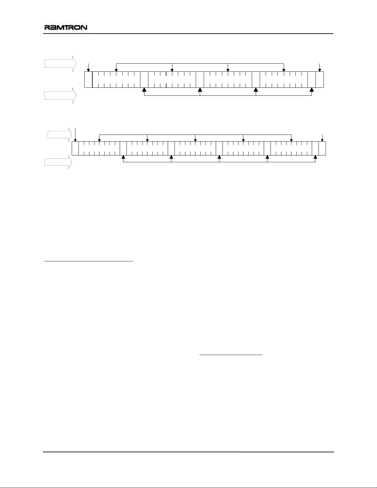
By Master
FM24CL64
Start Address & Data
Stop
S ASlave Address 0 Address MSB A Data Byte A P
By FM24CL64
Figure 5. Single Byte Write
Start
By Master
S ASlave Address 0 Address MSB A Data Byte A P
By FM24CL64
Address & Data
Acknowledge
Figure 6. Multiple Byte Write
Read Operation
There are two basic types of read operations. They
are current address read and selective address read. In
a current address read, the FM24CL64 uses the
internal address latch to supply the address. In a
selective read, the user performs a procedure to set
the address to a specific value.
Current Address & Sequential Read
As mentioned above the FM24CL64 uses an internal
latch to supply the address for a read operation. A
current address read uses the existing value in the
address latch as a starting place for the read
operation. The system reads from the address
immediately following that of the last op eration.
To perform a current address read, the bus master
supplies a device a ddress wi th the LSB set to 1. T his
indicates that a read operation is requested. After
receiving the complete device address, the
FM24CL64 will begin shifting out data from the
current address on the next clock. The current address
is the value held in the internal address latch.
Beginning with the current address, the bus master
can read any number of bytes. Thus, a sequential read
is simply a current address read with multiple byte
transfers. After each byte the internal address counter
will be incremented.
Each time the bus master acknowledges a byte,
this indicates that the FM24CL64 should read
out the next sequential byte.
Address LSB A
Acknowledge
Address LSB A Data Byte A
There are four ways to properly terminate a read
operation. Failing to p roperly terminate the read will
most likely create a bus contention as the FM24CL64
attempts to read out additional da ta onto the bus. The
four valid methods are:
1. The bus master issues a no-acknowledge in the
th
9
clock cycle and a stop in the 10th clock cycle.
This is illustrated in the diagr ams below. This is
preferred.
2. The bus master issues a no-acknowledge in the
th
9
clock cycle and a start in the 10th.
3. The bus master issues a stop in the 9
cycle.
4. The bus master issues a start in the 9
cycle.
If the internal address reaches 1FFFh, it will wrap
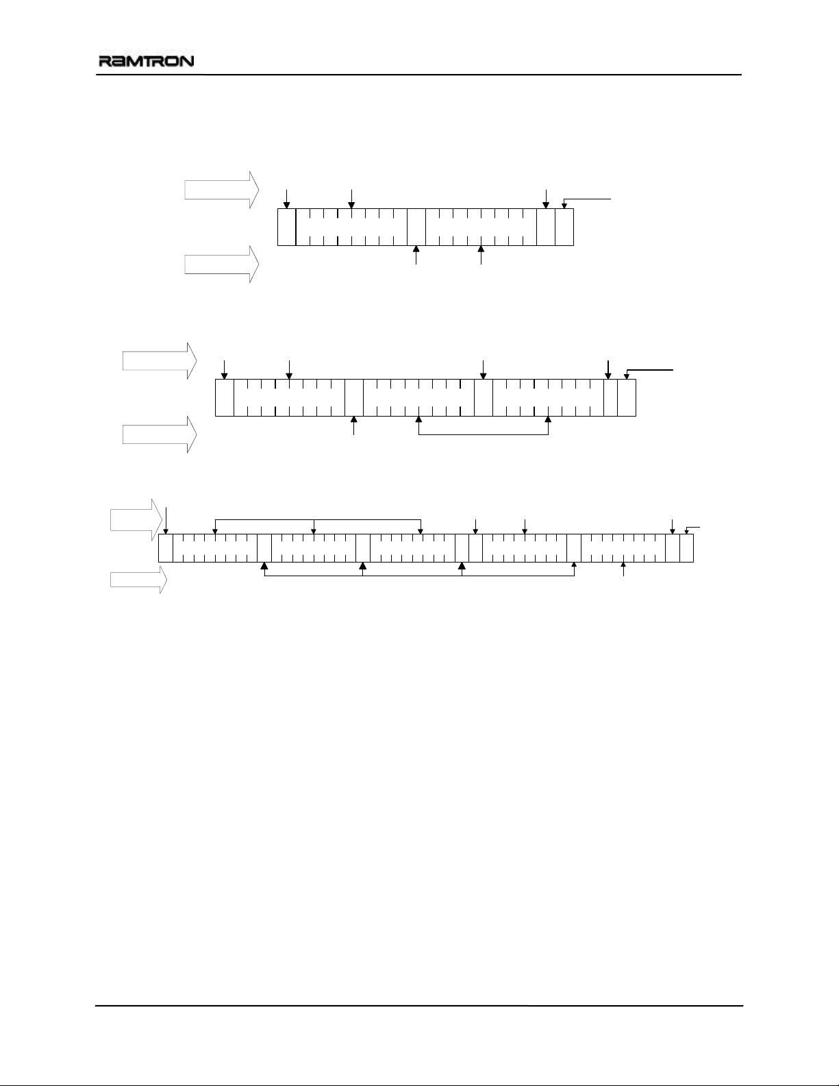
around to 0000h on the next read cycle. Figures 7 and
8 below show the proper operation for current
address reads.
Selective (Random) Read
There is a simple technique that allows a user to
select a random address location as the starting point
for a read operation. This involves using the first
three bytes of a write operation to set the internal
address followed by subsequent read operations.
To perform a selective read, the bus master sends out
the device address with the LSB set to 0. This
specifies a write operation. According to the write
protocol, the bus master then sends the address bytes
that are loaded into the internal address latch. After
the FM24CL64 acknowledges the address, the bus
Stop
th
clock
th
clock
Rev. 3.1
Mar. 2005 Page 6 of 13
Page 7
FM24CL64
master issues a start condition. This simultaneously
aborts the write operation and allows the read
command to be issued with the device address LSB
set to a 1. The operation is now a current address
read.
By Master
By FM24CL64
Start
By Master
S ASlave Address 0 Address MSB A
No
Acknowledge
By Master
By FM24CL64
Start Address
S ASlave Address 1 Data Byte 1 P
Acknowledge
Data
Figure 7. Current Address Read
Start Address
S ASlave Address 1 Data Byte 1 P
Acknowledge
Acknowledge
Data ByteA
Data
Figure 8. Sequential Read
Address
Address LSB A
Start Address
S ASlave Address 1 Data Byte 1 P
Stop
No
Acknowledge
Stop
No
Acknowledge
Stop
By FM24CL64
Acknowledge
Figure 9. Selective (Random) Read
Data
Rev. 3.1
Mar. 2005 Page 7 of 13
Page 8
FM24CL64
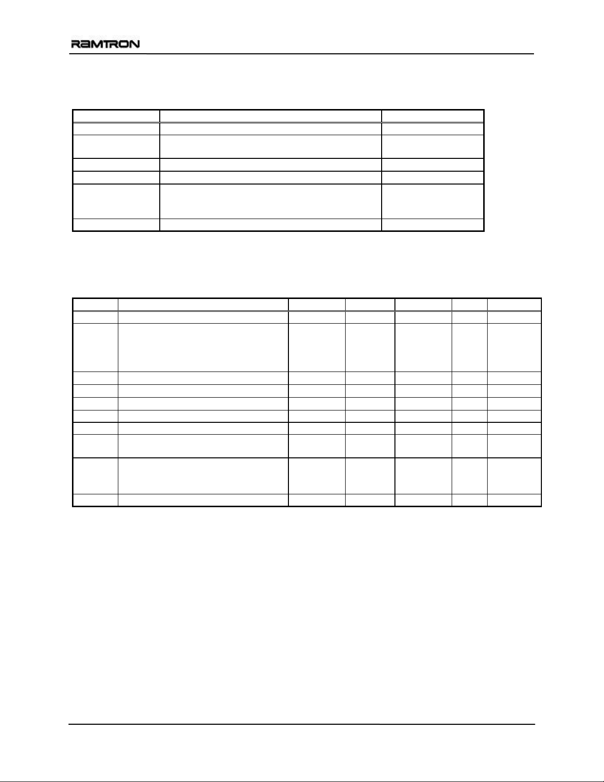
Electrical Specifications
Absolute Maximum Ratings
Symbol Description Ratings
VDD Power Supply Voltage with respect to VSS -1.0V to +5.0V
VIN Voltage on any pin with respect to VSS -1.0V to +5.0V
and V
< VDD+1.0V *
IN
T
Storage Temperature
STG
T
Lead Temperature (Soldering, 10 seconds)
LEAD
V
Electrostatic Discharge Voltage
ESD
- Human Body Model
- Machine Model
(JEDEC Std JESD22-A115-A)
(JEDEC Std JESD22-A114-B)
Package Moisture Sensitivity Level MSL-1
* Exception: The “VIN < VDD+1.0V” restriction does not apply to the SCL and SDA inputs.
Stresses above th ose list ed und er Absolut e Maximum Ratings may cau se permanen t dama ge to the d evice. Thi s is a s tress rati ng
only, and the functional operation of the device a t these or any other conditions above those listed in the operational s ection of this
specification is not implied. Exposure to absolute maximum ratings conditions for extended periods may affect device reliability.
DC Operating Conditions (T
= -40° C to + 85° C, VDD =2.7V to 3.65V unless otherwise specified)
A
Symbol Parameter Min Typ Max Units Notes
VDD Main Power Supply 2.7 3.65 V
IDD V
Supply Current
DD
@ SCL = 100 kHz
@ SCL = 400 kHz
@ SCL = 1 MHz
ISB Standby Current 1
ILI Input Leakage Current ±1
ILO Output Leakage Current ±1
VIL Input Low Voltage -0.3 0.3 VDD V
VIH Input High Voltage 0.7 VDD V
VOL Output Low Voltage
@ I
= 3.0 mA
OL
RIN Address Input Resistance (WP, A2-A0)
= VIL
(max)
(min)
For V
IN
For V
V
Input Hysteresis 0.05 VDD V 4
HYS
= VIH
IN
0.4 V
50
1
Notes
1. SCL toggling between V
2. SCL = SDA = V
3. VIN or VOUT = V
. All inputs VSS or VDD. Stop command issued.
DD
SS
-0.3V and VSS, other inputs VSS or VDD-0.3V.
DD
to VDD. Does not apply to WP, A2-A0 pins.
4. This parameter is characterized but not tested.
5. The input pull-down circuit is strong (50KΩ) when the input voltage is below V
input voltage is above V
.
IH
-55°C to +125°C
300° C
4kV
300V
75
150
400
µA
µA
µA
µA
µA
µA
+ 0.5 V
DD
KΩ
1
2
3
3
5
MΩ
and weak (1MΩ) when the
IL
Rev. 3.1
Mar. 2005 Page 8 of 13
Page 9

FM24CL64
AC Parameters (TA = -40° C to + 85° C, VDD =2.7V to 3.65V unless otherwise specified)
Symbol Parameter Min Max Min Max Min Max Units Notes
f
SCL Clock Frequency 0 100 0 400 0 1000 kHz 1
SCL
t
Clock Low Period 4.7 1.3 0.6
LOW
t
Clock High Period 4.0 0.6 0.4
HIGH
tAA SCL Low to SDA Data Out Valid 3 0.9 0.55
t
Bus Free Before New
BUF
4.7 1.3 0.5
µs
µs
µs
µs
Transmission
t
Start Condition Hold Time 4.0 0.6 0.25
HD:STA
t
Start Condition Setup for Repeated
SU:STA
4.7 0.6 0.25
µs
µs
Start
t
Data In Hold 0 0 0 ns
HD:DAT
t
Data In Setup 250 100 100 ns
SU:DAT
tR Input Rise Time 1000 300 300 ns 2
tF Input Fall Time 300 300 100 ns 2
t
Stop Condition Setup 4.0 0.6 0.25
SU:STO
tDH Data Output Hold
(from SCL @ V
)
IL
tSP Noise Suppression Time Constant
0 0 0 ns
50 50 50 ns
µs
on SCL, SDA
Notes : All SCL specifications as well as start and stop conditions apply to both read and write operations.
1 The speed-related specifications are guaranteed characteristic points along a continuous curve of operation from
DC to 1 MHz.
2 This parameter is periodically sampled and not 100% tested.
Capacitance (T
= 25° C, f=1.0 MHz, VDD = 3V)
A
Symbol Parameter Max Units Notes
C
Input/output capacitance (SDA) 8 pF 1
I/O
CIN Input capacitance 6 pF 1
Notes
1 This parameter is periodically sampled and not 100% tested.
AC Test Conditions
Input Pulse Levels 0.1 V
to 0.9 VDD
DD
Input rise and fall times 10 ns
Input and output timing levels 0.5 V
DD
Equivalent AC Load Circuit
3.65V
1100
Ω
Output
100 pF
Rev. 3.1
Mar. 2005 Page 9 of 13
Page 10
FM24CL64
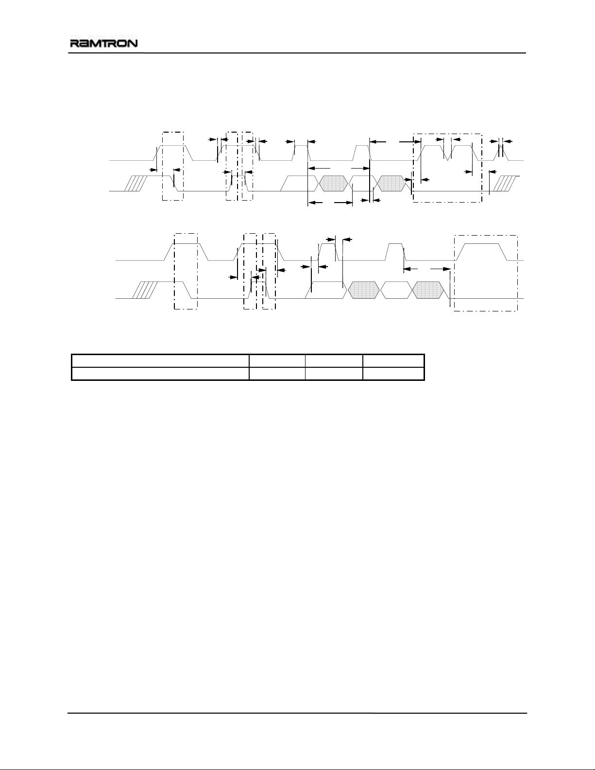
Diagram Notes
All start and stop timing parameters apply to both read and write cycles. Clock specifications are identical for read
and write cycles. Write timing parameters apply to slave address, word address, and write data bits. Functional
relationships are illustrated in the r e levant datasheet sections. These d iagr ams illustrate the timing parameters only.
Read Bus Timing
t
t
R
HIGH
t
F
`
t
LOW
t
SP
t
SP
SCL
t
AA
1/fSCL
t
HD:DAT
t
SU:DAT
t
DH
Acknowledge
SDA
t
SU:SDA
Start
t
BUF
Stop Start
Write Bus Timing
t
HD:DAT
SCL
t
SU:STO
t
HD:STA
t
SU:DAT
t
AA
SDA
Start
Stop Start Acknowledge
Data Retention
(VDD = 2.7V to 3.65V, 85°C)
Parameter Min Units Notes
Data Retention 45 Year s
Rev. 3.1
Mar. 2005 Page 10 of 13
Page 11
FM24CL64
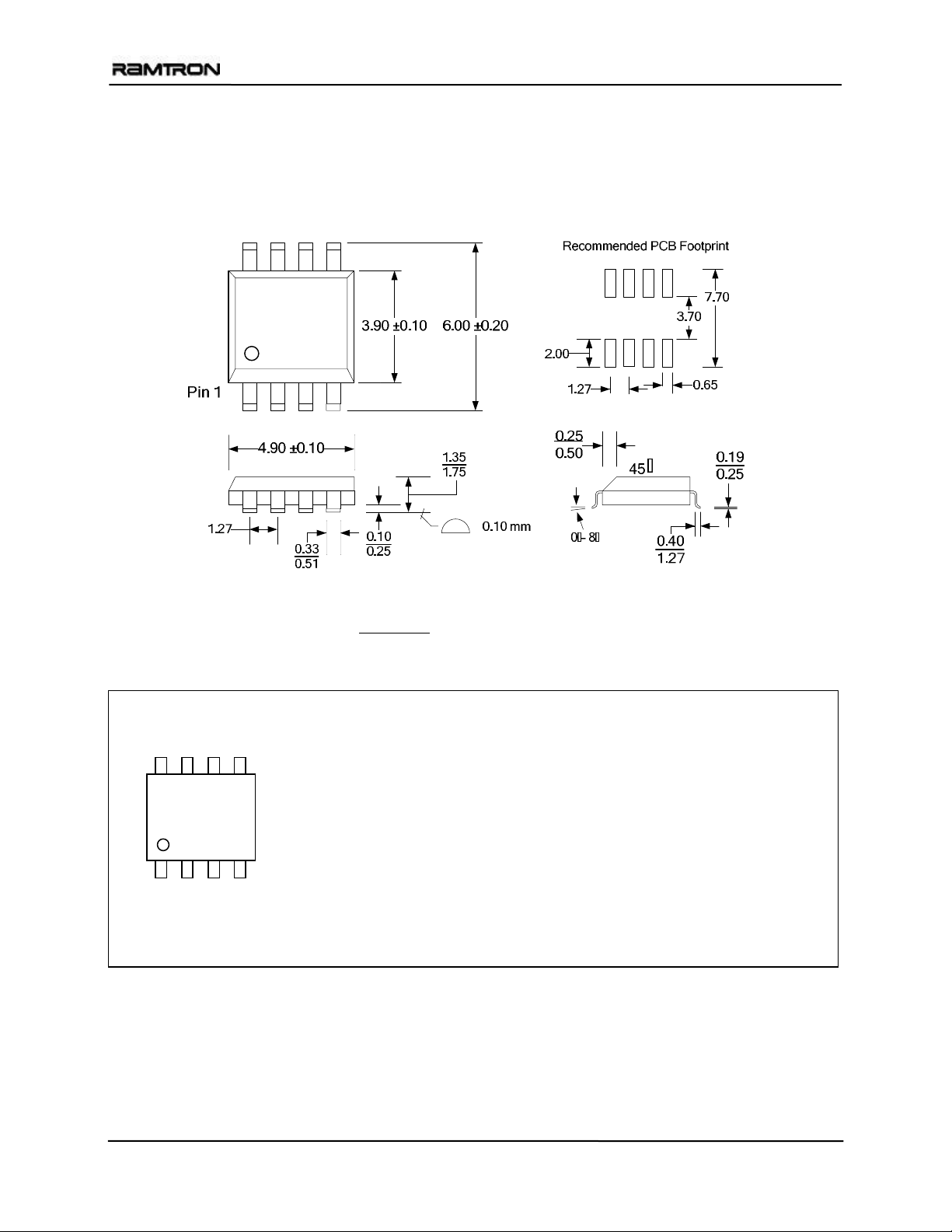
Mechanical Drawing
8-pin SOIC (JEDEC Standard MS-012 variation AA)
Refer to JEDEC MS-012 for complete dimensions and notes.
All dimensions in millimeters
.
SOIC Package Marking Scheme
Legend:
XXXX= part number, P= package type
LLLLLLL= lot code
XXXXXXX-P
RIC=Ramtron Int’l Corp, YY=year, WW=work week
LLLLLLL
Example: FM24CL64, Standard SOIC package, Year 2004, Work Week 39
FM24CL64-S
A40003S
RIC0439
RICYYWW
Rev. 3.1
Mar. 2005 Page 11 of 13
Page 12
FM24CL64
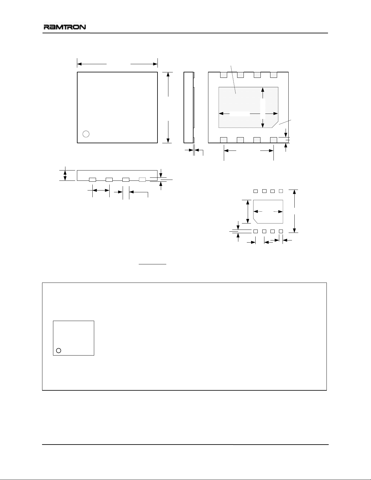
8-pin DFN (4.0mm x 4.5mm body , 0.95mm pitch)
4.50 ±0.1
Exposed metal pad.
Do not connect to
anything except Vss.
Pin 1
0.75 ±0.05
0.95
0.40 ±0.05
Note: All dimensions in millimeters
4.00 ±0.1
0.20 REF.
.
3.60 ±0.10
2.85 REF
0.0 - 0.05
Recommended PCB Footprint
2.70
0.40
0.95
2.60 ±0.10
.
0
3
7
Pin 1 ID
0.30 ±0.1
4.30
0.45
DFN Package Marking Scheme for Body Size 4.0mm x 4.5mm
Legend:
RIC=Ramtron Int’l Corp, G=”green” DFN package
XXXX=base part number
RICG
LLLL= lot code
YY=year, WW=work week
Example: “Green” DFN package, FM24CL64, Lot 0003, Year 2005, Work Week 14
RICG
4L64
0003
0514
XXXX
LLLL
YYWW
Rev. 3.1
Mar. 2005 Page 12 of 13
Page 13
FM24CL64
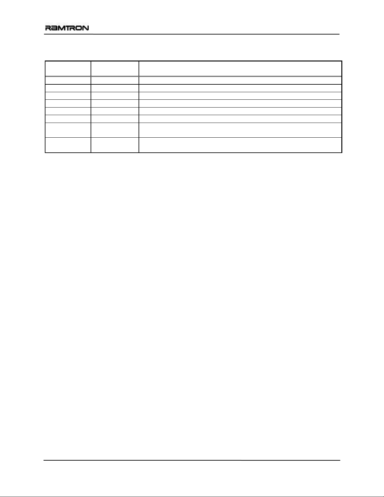
Revision History
Revision
0.1 7/21/00 Initial Release
0.2 5/9/01 Endurance changed to unlimited.
0.3 10/11/01 Changed Data Retention table. Added pin numbers to pinout.
1.0 3/29/02 Changed status to Preliminary.
2.0 7/23/03 Changed status to Production. Extended storage temperature limits.
2.1 3/17/04 Added “green” package. Updated package drawing.
3.0 1/19/05 Added DFN package ordering option and added mechanical drawing. Added
3.1 3/8/05 Improved Data Retention spec to 45 years. Removed “preliminary” from
Date
Summary
st
pcb footprint drawings. Updated 1
page footer.
DFN package drawing. Added ESD and package MSL ratings.
Rev. 3.1
Mar. 2005 Page 13 of 13
 Loading...