

Page 1

Philips Semiconductors
FBL22033
3.3V BTL 8-bit latched/registered/pass-thru
Futurebus+ universal interface transceiver
Product specification 1999 Apr 15
INTEGRATED CIRCUITS
IC23 data handbook
Page 2
Philips Semiconductors Product specification
FBL22033
3.3V BTL 8-bit latched/registered/pass-thru
universal transceiver with 30Ω termination
2
1999 Apr 15 853–2157 21253
FEA TURES
•8-bit transceivers
•Latched, registered or straight through in either A to B or B to A
path
•Drives heavily loaded backplanes with equivalent load
impedances down to 10Ω.
•High drive 100mA BTL Open Collector drivers on B-port
•Allows incident wave switching in heavily loaded backplane buses
•Reduced BTL voltage swing produces less noise and reduces
power consumption
•Built-in precision band-gap reference provides accurate receiver
thresholds and improved noise immunity
•Compatible with IEEE Futurebus+ or proprietary BTL backplanes
•Each BTL driver has a dedicated Bus GND for a signal return
•Controlled output ramp and multiple GND pins minimize ground
bounce
•Glitch-free power up/power down operation
•Low I
CC
current
•Tight output skew
•Supports live insertion
•Pins for the optional JTAG boundary scan function are provided
•High density packaging in plastic Quad Flatpack
•5V compatible I/O on A-port
•Same pinout and function as the FBL2033 except for 30Ω series
termination on 4 outputs making external resistors unnecessary
•A port outputs include 30Ω termination to reduce overshoot and
undershoot
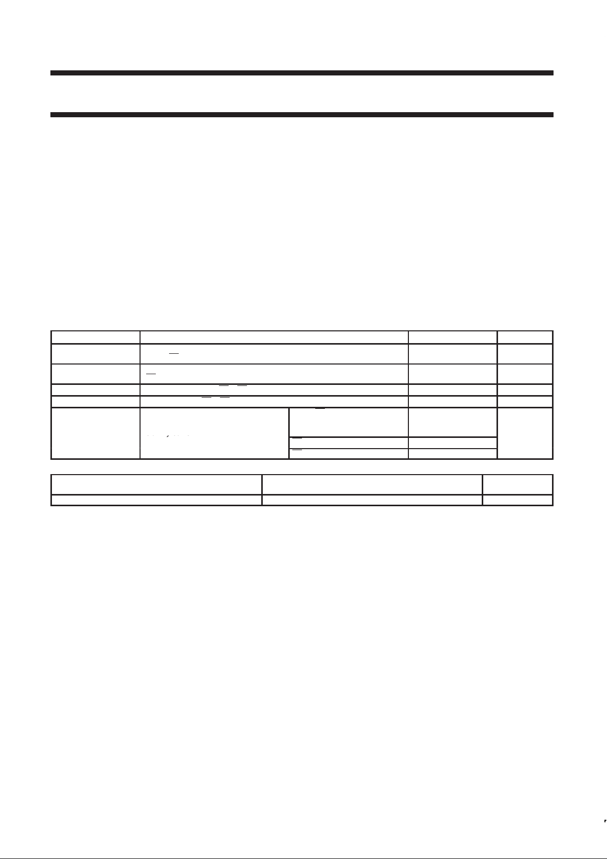
QUICK REFERENCE DA TA
SYMBOL PARAMETER TYPICAL UNIT
t
PLH
t
PHL
Propagation delay
AIn to Bn
3.0
3.0
ns
t
PLH
t
PHL
Propagation delay
Bn to AOn
5.1
5.5
ns
C
OB
Output capacitance (B0 – Bn only) 6 pF
I
OL
Output current (B0 – Bn only) 100 mA
I
Supply current
AIn to Bn
outputs Low
outputs High
9
14
mA
I
CC
Su ly current
Bn to AOn (outputs Low) 17
mA
Bn to AOn (outputs High) 14
ORDERING INFORMATION
PACKAGE
COMMERCIAL RANGE
VCC = 3.3V±10%; T
amb
= –40°C to +85°C
DWG
No.
52-pin Plastic Quad Flat Pack (PQFP) FBL2033BB SOT379-1
NOTE: Thermal mounting or forced air is recommended
Page 3
Philips Semiconductors Product specification
FBL22033
3.3V BTL 8-bit latched/registered/pass-thru
universal transceiver with 30Ω termination
1999 Apr 15
3
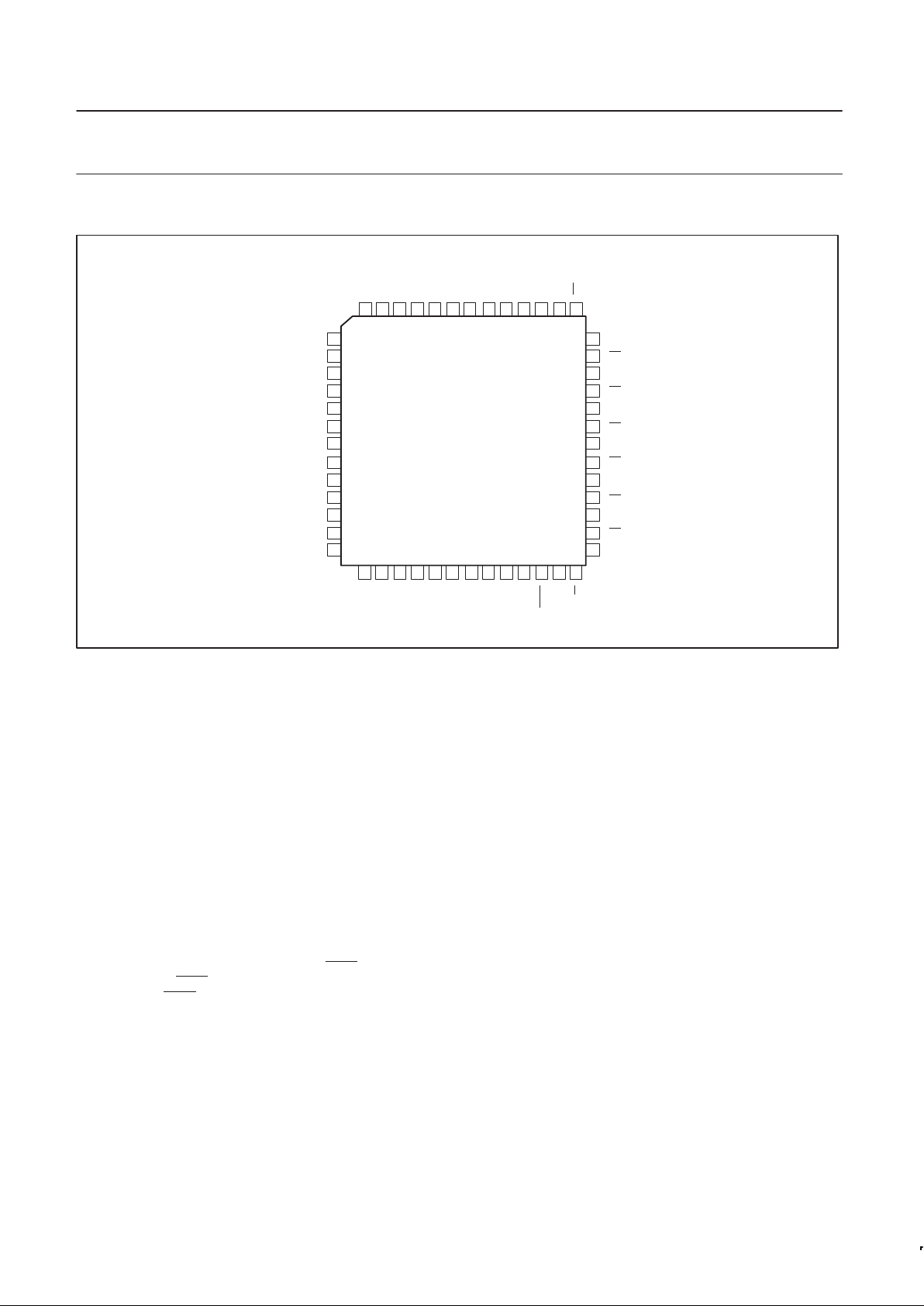
PIN CONFIGURATION
OEB0
52 51 50 49 48 47 46 45 44 43 42 41 40
39
38
37
36
35
34
33
32
31
30
29
28
27
1
2
3
4
5
6
7
8
9
10
11
12
13
14 15 16 17 18 19 20 21 22 23 24 25 26
BUS GND
B1
BUS GND
B2
BUS GND
B3
BUS GND
B4
BUS GND
B5
BUS GND
B6
BUS GND
LOGIC GND
AO1
AO2
AO3
LOOPBACK
AI4
AI5
AO6
AO7
B7
AI1
AO0
OEA
LCBA
BIAS V
B0
LGOIC GND
LCAB
8-Bit Universal Transceiver
FBL22033
52-lead PQFP
BG GND
OEB1
LOGIC GND
V
CC
AI2
AI3
AO4
AI6
LOGIC GND
AI7
SAB0
SAB1
V
CC
BUS GND
V
CC
AO5
AI0
SBA1
SBA0
BG V
CC
SG00092
DESCRIPTION
The FBL22033 is an 8-bit transceiver featuring a split input (AI) and
output (AO) bus on the TTL-level side.
The common I/O, open collector B port operates at BTL signal
levels. The logic element for data flow in each direction is controlled
by two pairs of mode select inputs (SBA0 and SBA1 for B-to-A,
SAB0 and SAB1 for A-to-B). It can be configured as a buffer, a
register, or a D-type latch.
When configured in the buffer mode, the inverse of the input data
appears at the output port. In the flip-flop mode, data is stored on
the rising edge of the appropriate clock input (LCAB or LCBA). In the
latch mode, clock pins serve as transparent-High latch enables.
Regardless of the mode, data is inverted from input to output.
Data flow in the B-to-A direction, regardless of the logic element
selected, is further controlled by the Loopback input. When the
Loopback input is High the output of the selected A-to-B logic
element (not inverted) becomes the B-to-A input.
The 3-State AO port is enabled by asserting a High level on OEA.
The B port has two output enables, OEB0 and OEB1
. Only when
OEB0 is High and OEB1
is Low is the output enabled. When either
OEB0 is Low or OEB1
is High, the B-port is inactive and is pulled to
the level of the pull-up voltage. New data can be entered in the
flip-flop and latched modes or can be retained while the associated
outputs are in 3-State (AO port) or inactive (B port).
The B-port drivers are Low-capacitance open collectors with
controlled ramp and are designed to sink 100mA. Precision band
gap references on the B-port ensure very good noise margins by
limiting the switching threshold to a narrow region centered at 1.55V .
The B-port interfaces to “Backplane Transceiver Logic” (see the
IEEE 1194.1 BTL standard). BTL features low power consumption
by reducing voltage swing (1V p-p, between 1V and 2V) and
reduced capacitive loading by placing an internal series diode on the
drivers. BTL also provides incident wave switching, a necessity for
high performance backplanes.
Output clamps are provided on the BTL outputs to further reduce
switching noise. The “V
OH
” clamp reduces inductive ringing effects
during a Low-to-High transition. The “V
OH
” clamp is always active.
The other clamp, the “trapped reflection” clamp, clamps out ringing
below the BTL 0.5V V
OL
level. This clamp remains active for
approximately 100ns after a High-to-Low transition.
To support live insertion, OEB0 is held Low during power on/off
cycles to ensure glitch- free B port drivers. Proper bias for B port
drivers during live insertion is provided by the BIAS V pin when at a
3.3V level while V
CC
is Low. The BIAS V pin is a low current input
which will reverse-bias the BTL driver series Schottky diode, and
also bias the B port output pins to a voltage between 1.62V and
2.1V. This bias function is in accordance with IEEE BTL Standard
1194.1. If live insertion is not a requirement, the BIAS V pin should
be tied to a V
CC
pin.
The LOGIC GND and BUS GND pins are isolated inside the
package to minimize noise coupling between the BTL and TTL
sides. These pins should be tied to a common ground external to the
package.
Each BTL driver has an associated BUS GND pin that acts as a
signal return path and these BUS GND pins are internally isolated
from each other. In the event of a ground return fault, a “hard” signal
failure occurs instead of a pattern dependent error that may be very
infrequent and impossible to trouble- shoot.
As with any high power device thermal considerations are
critical. It is recommended that airflow (300Ifpm) and/or thermal
mounting be used to ensure proper junction temperature.
Page 4
Philips Semiconductors Product specification
FBL22033
3.3V BTL 8-bit latched/registered/pass-thru
universal transceiver with 30Ω termination
1999 Apr 15
4
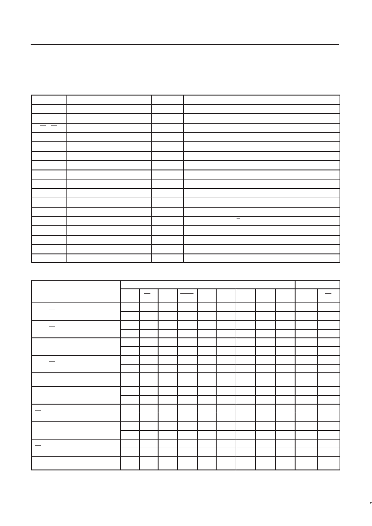
PIN DESCRIPTION
SYMBOL PIN NUMBER TYPE NAME AND FUNCTION
AI0 – AI7 50, 52, 3, 5, 8, 10, 12, 15 Input Data inputs (TTL)
AO0 – AO7 51, 2, 4, 6, 9, 11, 14, 16 Output 3-State outputs (TTL)
B0 – B7 40, 38, 36, 34, 32, 30, 28, 26 I/O Data inputs/Open Collector outputs, High current drive (BTL)
OEB0 23 Input Enables the B outputs when High
OEB1 24 Input Enables the B outputs when Low
OEA 43 Input Enables the AO outputs when High
BUS GND 39, 37, 35, 33, 31, 29, 27, 25 GND Bus ground (0V)
LOGIC GND 1, 13, 17, 49 GND Logic ground (0V)
V
CC
18, 22, 48 Power Positive supply voltage
BIAS V 41 Power Live insertion pre-bias pin
BG V
CC
44 Power Band Gap threshold voltage reference
BG GND 42 GND Band Gap threshold voltage reference ground
SABn 20, 21 Input Mode select from AI to B
SBAn 45, 46 Input Mode select from B to AO
LCAB 47 Input A-to-B clock/latch enable (transparent latch when High)
LCBA 19 Input B-to-A clock/latch enable (transparent latch when High)
Loopback 7 Input Enables loopback function when High (from AIn to AOn)
FUNCTION TABLE
INPUTS OUTPUTS
MODE
AIn Bn* OEB0 OEB1 OEA LCAB LCBA
SAB
1
0
SBA
1
0
AOn Bn
L — H L L X X LL XX Z H**
AIn to Bn thru mode
H — H L L X X LL XX Z L
p
L — H L L H X HX XX Z H**
AIn to Bn transparent latch
H — H L L H X HX XX Z L
l — H L L ↓ X HX XX Z H**
AIn to Bn latch and read
h — H L L ↓ X HX XX Z L
L — H L L ↑ X LH XX Z H**
AIn to Bn register
H — H L L ↑ X LH XX Z L
Bn outputs latched and read
(preconditioned latch)
X — H L L L X HX XX Z
latched
data
X L L H H X X XX LL H input
Bn to AOn thru mode
X H L H H X X XX LL L input
p
X L L H H X H XX HX H input
Bn to AOn transparent latch
X H L H H X H XX HX L input
X l L H H X ↓ XX HX H input
Bn to AOn latch and read
X h L H H X ↓ XX HX L input
X L L H H X ↑ XX LH H input
Bn to AOn register
X H L H H X ↑ XX LH L input
AOn outputs latched and read
(preconditioned latch)
X X L H H X L XX HX
latched
data
X
Page 5
Philips Semiconductors Product specification
FBL22033
3.3V BTL 8-bit latched/registered/pass-thru
universal transceiver with 30Ω termination
1999 Apr 15
5
p
X X L X X X X XX XX X H**
Disable Bn outputs
X X X H X X X XX XX X H**
Disable AOn outputs X X X X L X X XX XX Z X
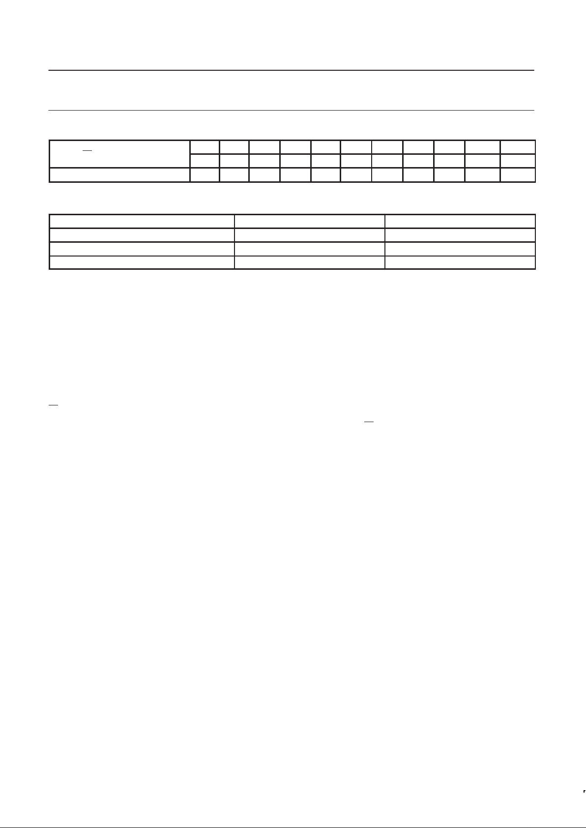
FUNCTION SELECT TABLE
MODE SELECTED SXX1 SXX0
Thru mode L L
Register mode L H
Latch mode H X
NOTES:
H = High voltage level
L = Low voltage level
h = High voltage level one set-up time prior to the High-to-Low LCXX transition
l = Low voltage level one set-up time prior to the High-to-Low LCXX transition
X = Don’t care
Z = High-impedance (OFF) state
— = Input not externally driven
↑ = Low-to-High transition
↓ = High-to-Low transition
H** = Goes to level of pull-up voltage
Bn
* = Precaution should be taken to ensure B inputs do not float. If they do, they are equal to Low state.
NOTE: In Loopback mode (Loopback = High), AIn inputs are routed to the AOn outputs. The Bn
inputs are blocked out.
Page 6
Philips Semiconductors Product specification
FBL22033
3.3V BTL 8-bit latched/registered/pass-thru
universal transceiver with 30Ω termination
1999 Apr 15
6
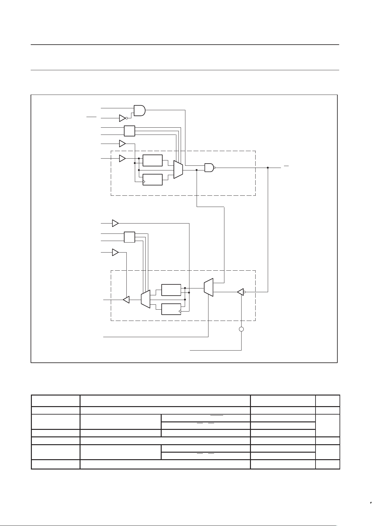
LOGIC DIAGRAM
23
24
OEB0
OEB1
20
SAB0
21
SAB1
47
LCAB
D
En
D
Clk
50
AIn
40
Bn
1 of 8 cells
19
45
46
43
D
En
D
Clk
51
LCBA
SBA0
SBA1
OEA
AOn
1 of 8 cells
42
BGGnd
BGref
52,
2, 5,
8, 10,
12, 15
2, 4, 6, 9,
11, 14, 16
38,
36, 34,
32, 30,
28, 26
7
Loopback
SG00069
ABSOLUTE MAXIMUM RATINGS
Operation beyond the limits set forth in this table may impair the useful life of the device. Unless otherwise noted these limits are over the
operating free-air temperature range.
SYMBOL
PARAMETER RATING UNIT
V
CC
Supply voltage -0.5 to +4.6 V
p
AI0 – AI7, OEB0, OEBn, OEAn -0.5 to +7.0 V
V
IN
In ut voltage
B0 – B7 -0.5 to +3.5
I
IN
Input current VIN 0 -50
V
OUT
Voltage applied to output in High output state -0.5 to +7.0 V
Current applied to output in AO0 – AO7 –24, 24
I
OUT
Low output state/High output state B0 – B7 200
mA
T
STG
Storage temperature -65 to +150 °C
Page 7
Philips Semiconductors Product specification
FBL22033
3.3V BTL 8-bit latched/registered/pass-thru
universal transceiver with 30Ω termination
1999 Apr 15
7
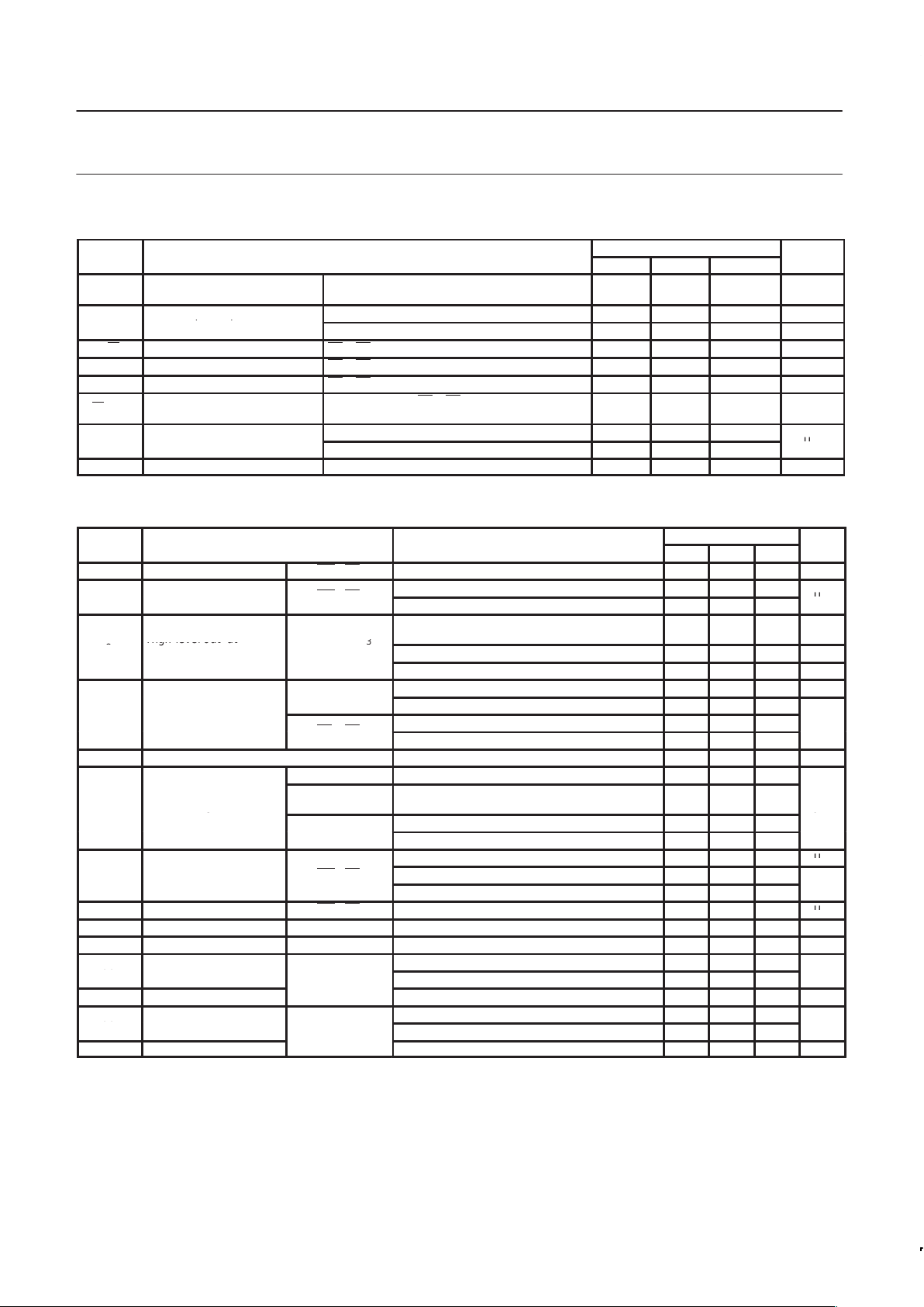
LIVE INSERTION SPECIFICA TIONS
LIMITS
SYMBOL
PARAMETER
MIN TYP MAX
UNIT
V
BIASV
Bias pin voltage
Voltage dif ference between the Bias voltage
and VCC after the PCB is plugged in.
– – 0.5 V
Bias pin (I
BIASV
) input
VCC = 0 V, Bias V = 3.6V 1.2 mA
I
BIASV
(
BIASV
)
DC current
VCC = 3.3V, Bias V = 3.6V 10 µA
V
Bn
Bus voltage during prebias B0 – B7 = 0V, Bias V = 3.3V 1.62 2.1 V
I
LM
Fall current during prebias B0 – B7 = 2V, Bias V = 1.3 to 2.5V 1 µA
I
HM
Rise current during prebias B0 – B7 = 1V, Bias V = 3 to 3.6V -1 µA
IBnPEAK
Peak bus current during
insertion
VCC = 0 to 3.3V , B0 – B7 = 0 to 2.0V,
Bias V = 2.7 to 3.6V, OEB0 = 0.8V, tr = 2ns
10 mA
p
V
CC
= 0 to 3.3V , OEB0 = 0.8V 100
IOLOFF
Power u current
V
CC
= 0 to 1.2V, OEB0 = 0 to 5V 100
µA
t
GR
Input glitch rejection VCC = 3.3V 1.0 1.35 ns
DC ELECTRICAL CHARACTERISTICS
Over recommended operating free-air temperature range unless otherwise noted.
p
1
limits
symbol
arameter
test conditions
1
min typ2max
unit
I
OH
High level output current B0 – B7 VCC = MAX, VIL = MAX, VOH = 1.9V 100 µA
p
VCC = 0V, VIL = MAX, VOH = 1.9V 100
I
OFF
Power-off out ut current
B0
–
B7
VCC = 0V, VIL = MAX, VOH = 1.9V@85°C 300
µA
High-level output
VCC = MIN to MAX; IOH = -100µA
V
CC
–0.2
V
V
OH
High level out ut
voltage
AO0
–
AO7
3
VCC = MIN; IOH = -8mA 2.4 V
VCC = MIN; IOH = -32mA 2.0 V
3
VCC = MIN; IOL = 16mA 0.4 V
V
OL
Low-level output voltage
AO0
–
AO7
3
VCC = MIN; IOL = 32mA 0.8 V
VCC = MIN, IOL = 4mA 0.5
B0
–
B7
VCC = MIN, IOL = 100mA 0.75 1.0 1.20
V
V
IK
Input clamp voltage VCC = MIN, II = I
IK
= –18mA –0.85 -1.2 V
Control pins VCC = 3.6V; VI = VCC or 300mV ±1.0
I
I
Input leakage current
Control/
AI0 – AI7
VCC = 0V or 3.6V; VI = 5.5V 10
µA
I
g
AI0 – AI7 VCC = 3.6V; VI = V
CC
1
µ
Note 4 VCC = 3.6V; VI = 300mV –5
V
CC
=
MAX, V
I
= 1.
9V
100
µA
I
IH
High-level input current B0 – B7 VCC = MAX, VI = 3.5V , note 5 100
VCC = MAX, VI = 3.75V , Note 5 @ –40 °C 100
mA
p
IILLow-level in ut current
B0
–
B7
V
CC
=
MAX, V
I
= 0.
75V
-
100
µA
I
OZH
Off-state output current AO0 – AO7 VCC = MAX, VO =3V 5 µA
I
OZL
Off-state output current AO0 – AO7 VCC = MAX, VO = 0.5V -5 µA
I
CCH
pp
VCC = MAX, outputs High 14 31
CCH
I
CCL
Su ly current (total)
B→A VCC = MAX, outputs Low 17 38
mA
I
CCZ
Supply current VCC = MAX 22 55 mA
I
CCH
pp
VCC = MAX, outputs High 14 32
CCH
I
CCL
Su ly current (total)
A→B VCC = MAX, outputs Low 9 18
mA
I
CCZ
Supply current VCC = MAX 14 33 mA
NOTES:
1. For conditions shown as MIN or MAX, use the appropriate value specified under recommended operation conditions for the applicable type.
2. All typical values are at V
CC
= 3.3V , TA = 25°C.
3. Due to test equipment limitations, actual test conditions are V
IH
= 1.8V and VIL = 1.3V for the B side.
4. Unused pins are at V
CC
or GND.
5. For B port input voltage between 3 and 5 volt; I
IH
will be greater than 100mA but the part will continue to function normally (clamping circuit
is active).
Page 8
Philips Semiconductors Product specification
FBL22033
3.3V BTL 8-bit latched/registered/pass-thru
universal transceiver with 30Ω termination
1999 Apr 15
8
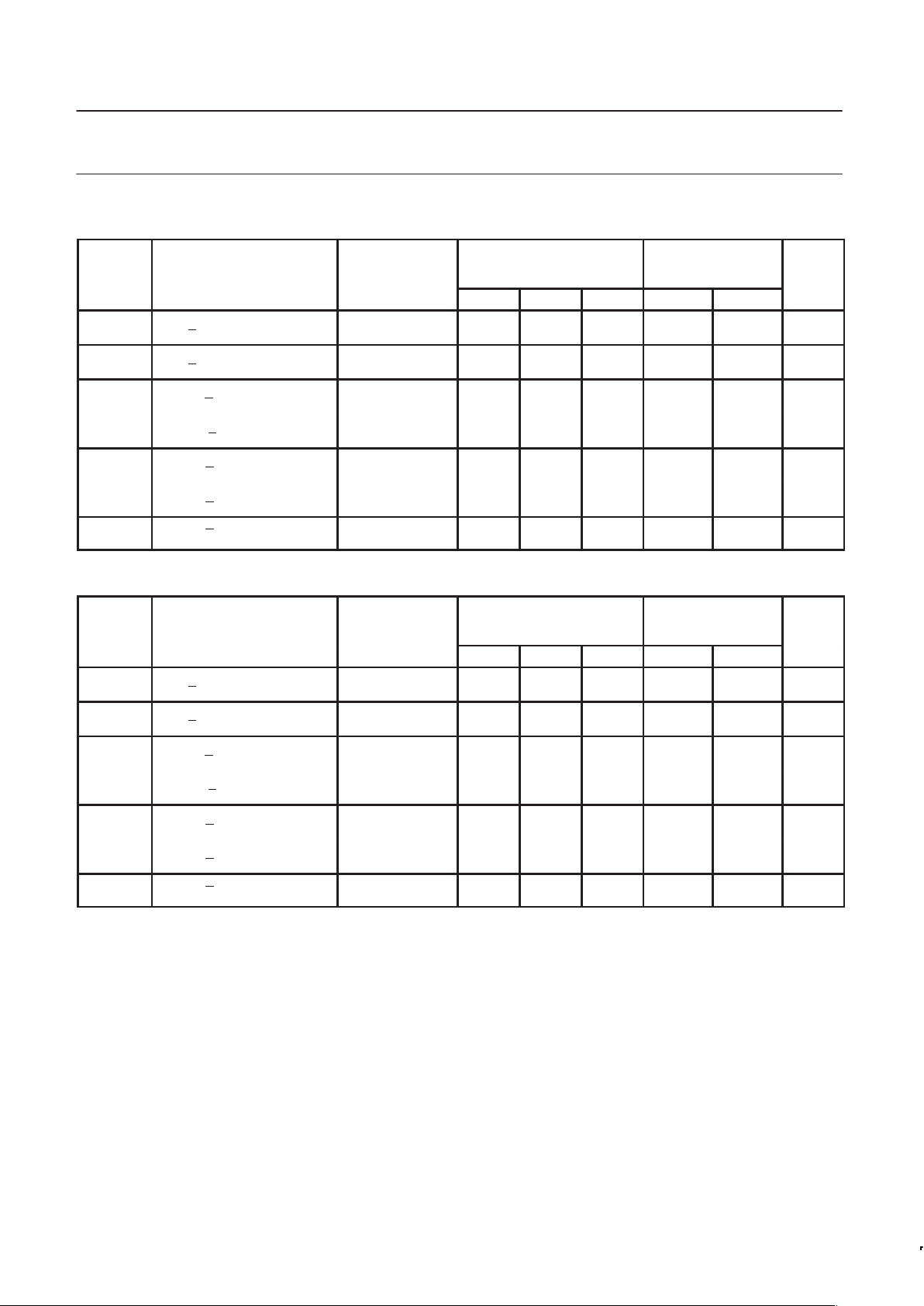
AC ELECTRICAL CHARACTERISTICS INDUSTRIAL AND COMMERCIAL (A TO B)
SYMBOL PARAMETER TEST CONDITION
T
amb
= +25°C, VCC = 3.3V ,
RL = 9Ω
T
amb
= –40 to +85°C,
VCC = 3.3V±10%,
R
L
= 9Ω
UNIT
MIN TYP MAX MIN MAX
t
PLH
t
PHL
Propagation delay,
An to Bn through latch
1.2
1.2
2.7
2.6
4.8
4.3
1.0
1.0
5.3
4.9
ns
t
PLH
t
PHL
Propagation delay,
An to Bn transparent latch
1.3
1.8
3.2
3.7
5.2
5.6
1.0
1.6
6.1
6.3
ns
t
PLH
t
PHL
Propagation delay,
LCAB to Bn latch
2.0
2.3
3.8
4.3
5.8
6.3
1.2
1.8
7.0
7.3
ns
t
PLH
t
PHL
Propagation delay,
LCAB to Bn register
2.1
2.0
3.8
4.3
5.7
6.5
1.4
1.8
6.9
7.3
ns
t
PLH
t
PHL
Propagation delay,
SABX to Bn inverting
1.2
2.3
4.3
5.1
7.6
8.0
1.0
2.0
9.2
8.7
ns
t
PLH
t
PHL
Propagation delay,
SABX to Bn non-inverting
1.8
1.8
4.0
5.0
6.4
8.5
1.1
1.6
8.0
9.8
ns
t
PLH
t
PHL
OEBn to Bn
1.6
1.6
3.4
3.4
5.4
5.3
1.0
1.0
6.0
7.2
ns
AC ELECTRICAL CHARACTERISTICS INDUSTRIAL AND COMMERCIAL (A TO B)
SYMBOL PARAMETER TEST CONDITION
T
amb
= +25°C, VCC = 3.3V ,
RL = 16.5Ω
T
amb
= –40 to +85°C,
VCC = 3.3V±10%,
R
L
= 16.5Ω
UNIT
MIN TYP MAX MIN MAX
t
PLH
t
PHL
Propagation delay,
An to Bn through latch
1.2
1.2
2.8
2.4
4.5
4.0
1.0
1.0
5.7
4.6
ns
t
PLH
t
PHL
Propagation delay,
An to Bn transparent latch
1.4
1.7
3.2
3.5
5.1
5.4
1.0
1.3
6.1
5.9
ns
t
PLH
t
PHL
Propagation delay,
LCAB to Bn latch
2.0
2.2
3.8
4.1
5.6
6.1
1.3
1.6
6.9
7.0
ns
t
PLH
t
PHL
Propagation delay,
LCAB to Bn register
2.0
2.2
3.9
4.1
5.9
6.1
1.2
1.6
7.7
7.0
ns
t
PLH
t
PHL
Propagation delay,
SABX to Bn inverting
1.2
1.8
4.6
4.7
8.6
7.9
1.0
1.6
10.4
8.7
ns
t
PLH
t
PHL
Propagation delay,
SABX to Bn non-inverting
1.3
1.5
4.5
4.6
8.2
8.2
1.0
1.2
10.0
9.1
ns
t
PLH
t
PHL
OEBn to Bn
1.5
1.5
3.4
3.2
5.2
5.0
1.0
1.0
6.3
7.0
ns
Page 9
Philips Semiconductors Product specification
FBL22033
3.3V BTL 8-bit latched/registered/pass-thru
universal transceiver with 30Ω termination
1999 Apr 15
9
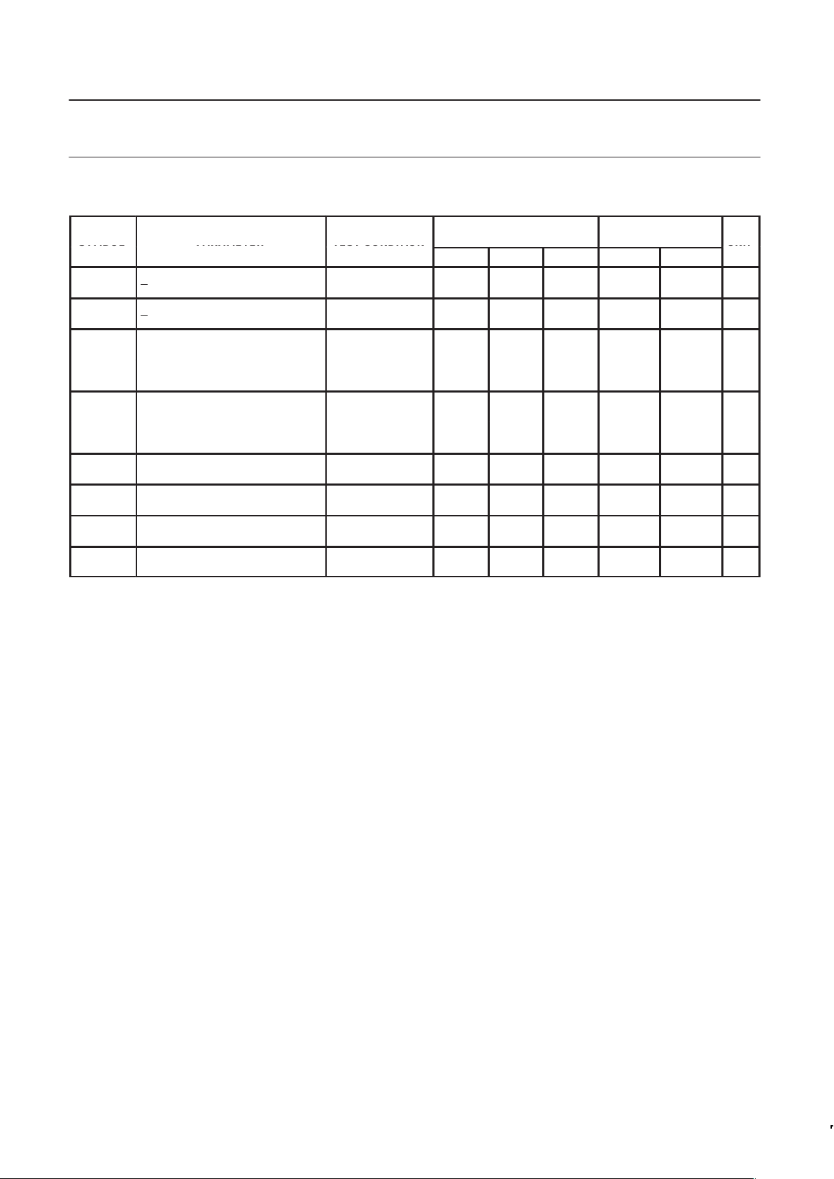
AC ELECTRICAL CHARACTERISTICS INDUSTRIAL AND COMMERCIAL (B TO A)
SYMBOL PARAMETER TEST CONDITION
T
amb
= +25°C, VCC = 3.3V
T
amb
= –40 to +85°C,
VCC = 3.3V±10%
UNIT
SYMBOL
PARAMETER
TEST CONDITION
MIN TYP MAX MIN MAX
UNIT
t
PLH
t
PHL
Propagation delay,
B
n to An through mode
2.2
2.9
4.6
5.4
7.0
7.8
1.6
2.5
8.1
9.2
ns
t
PLH
t
PHL
Propagation delay,
Bn to An transparent latch
3.1
3.0
5.6
5.6
8.1
8.1
2.1
2.8
9.6
9.4
ns
t
PLH
t
PHL
Propagation delay,
LCAB to An latch
1.9
1.7
3.7
3.5
6.1
5.2
1.3
1.2
7.5
6.0
ns
t
PLH
t
PHL
Propagation delay,
LCAB to An register
1.7
2.3
3.9
4.3
6.0
6.2
1.1
1.9
7.1
7.0
ns
t
PLH
t
PHL
Propagation delay,
SABX to An inverting
2.1
2.6
4.5
4.9
6.8
7.1
1.6
2.1
8.2
7.7
ns
t
PLH
t
PHL
Propagation delay,
SABX to An non-inverting
1.2
1.9
4.1
4.3
9.2
6.6
1.0
1.6
9.9
7.5
ns
t
PLH
t
PHL
Propagation delay,
AIn to AOn loopback
2.2
2.2
4.5
4.5
6.7
6.7
1.5
1.6
7.9
7.8
ns
t
PLH
t
PHL
Propagation delay,
LPBK to An non-inverting or inverting
1.7
1.2
4.6
5.4
7.5
9.6
1.5
1.0
9.3
11.1
ns
t
PZH
t
PHZ
Propagation delay,
OEA to An
2.1
2.3
4.6
5.2
6.8
8.1
1.8
2.0
7.7
9.2
ns
t
PZH
t
PHZ
Propagation delay,
OEA to An
2.0
1.2
4.5
3.0
7.0
4.7
1.8
1.0
7.6
5.3
ns
Page 10
Philips Semiconductors Product specification
FBL22033
3.3V BTL 8-bit latched/registered/pass-thru
universal transceiver with 30Ω termination
1999 Apr 15
10
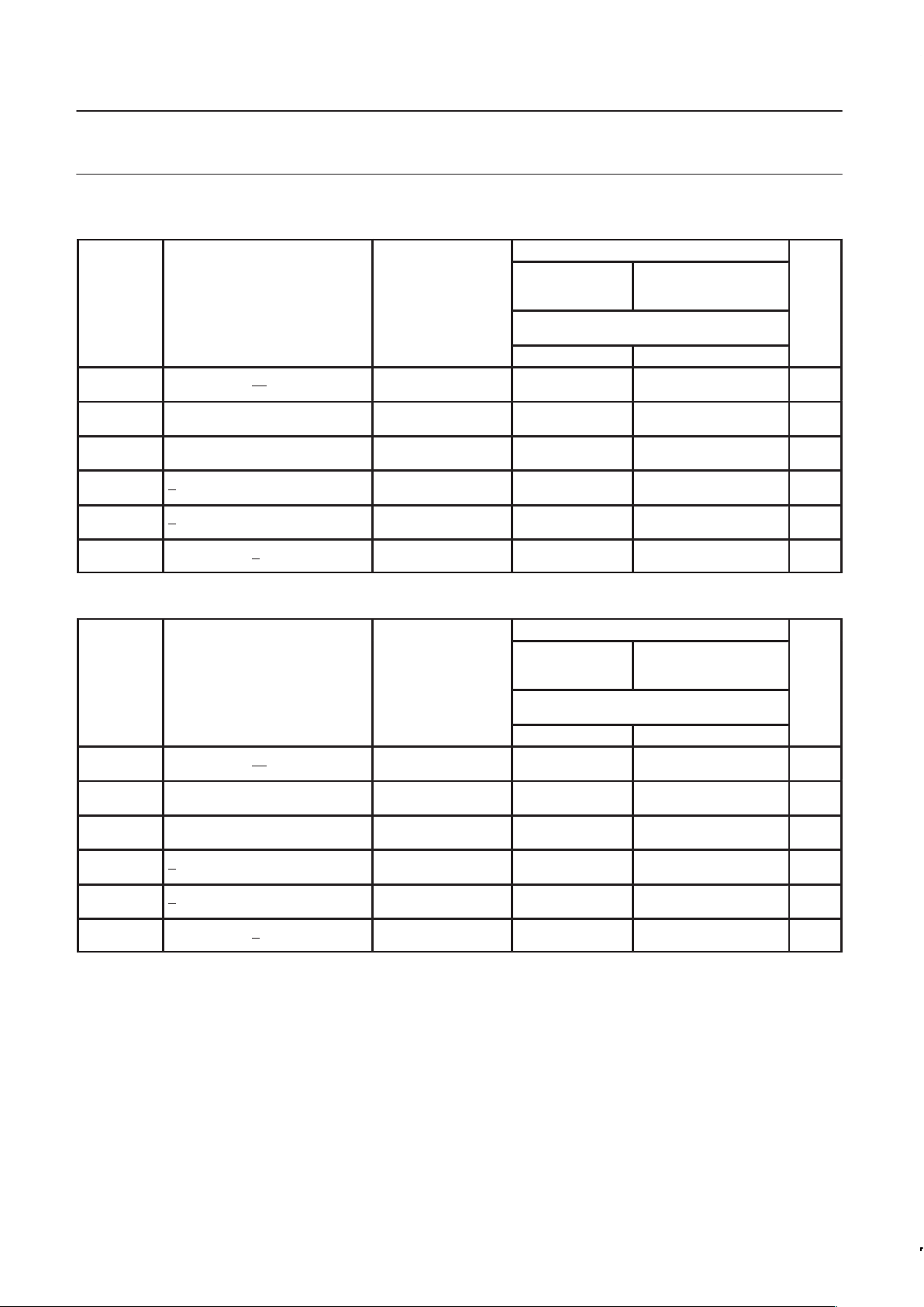
AC SETUP REQUIREMENTS INDUSTRIAL AND COMMERCIAL
LIMITS
SYMBOL PARAMETER
TEST
T
amb
= +25°C, V
CC
= 3.3V
T
amb
= –40 to +85°C,
V
CC
= 3.3V±10%
UNIT
CONDITION
CL = 50pF (A side) / CD = 30pF (B side)
RL = 500Ω (A side) / RU = 9Ω (B side)
MIN MIN
ts(H)
ts(L)
Setup time
AIn to LCAB or Bn to LCBA
3.0
3.0
4.0
4.0
ns
th(H)
th(L)
Hold time (latch mode)
AIn to LCAB
6.0
5.0
6.5
5.5
ns
th(H)
th(L)
Hold time (register mode)
AIn to LCAB
1.0
1.0
1.3
1.3
ns
th(H)
th(L)
Hold time (latch mode)
Bn to LCAB
1.5
1.5
2.0
2.0
ns
th(H)
th(L)
Hold time (register mode)
Bn to LCAB
1.0
1.0
1.3
1.3
ns
tw(H)
t
w
(L)
Pulse width, High or Low
AIn to LCAB or B
n to LCBA
3.0
3.0
4.0
4.0
ns
AC SETUP REQUIREMENTS INDUSTRIAL AND COMMERCIAL
LIMITS
SYMBOL PARAMETER
TEST
T
amb
= +25°C, V
CC
= 3.3V
T
amb
= –40 to +85°C,
V
CC
= 3.3V±10%
UNIT
CONDITION
CL = 50pF (A side) / CD = 30pF (B side)
RL = 500Ω (A side) / RU = 16.5Ω (B side)
MIN MIN
ts(H)
ts(L)
Setup time
AIn to LCAB or Bn to LCBA
3.0
3.0
4.0
4.0
ns
th(H)
th(L)
Hold time (latch mode)
AIn to LCAB
6.0
5.0
6.5
5.5
ns
th(H)
th(L)
Hold time (register mode)
AIn to LCAB
1.0
1.0
1.3
1.3
ns
th(H)
th(L)
Hold time (latch mode)
Bn to LCAB
1.5
1.5
2.0
2.0
ns
th(H)
th(L)
Hold time (register mode)
Bn to LCAB
1.0
1.0
1.3
1.3
ns
tw(H)
t
w
(L)
Pulse width, High or Low
AIn to LCAB or B
n to LCBA
3.0
3.0
4.0
4.0
ns
Page 11
Philips Semiconductors Product specification
FBL22033
3.3V BTL 8-bit latched/registered/pass-thru
universal transceiver with 30Ω termination
1999 Apr 15
11
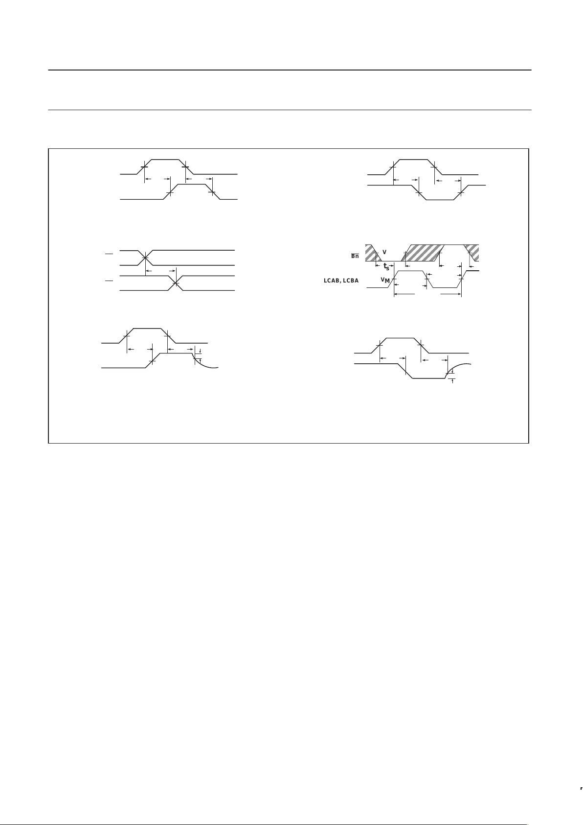
AC WAVEFORMS
V
M
t
s
t
PZL
Input
Output
V
M
V
M
V
M
V
M
t
PLH
t
PHL
V
M
V
M
V
M
V
M
t
PHL
t
PLH
Output
AIn, Bn
AOn, Bn
V
M
V
M
tSK(o)
AOn
OEA
V
M
V
M
t
PLZ
V
M
VOL +0.3V
AOn
OEA
V
M
V
M
V
M
VOH -0.3V
OV
t
PHZ
t
PZH
Input
AIn, Bn
LCAB, LCBA
V
M
V
M
1/f
MAX
t
h
tst
h
t
w
(L)
t
w
(H)
NOTE: The shaded areas indicate when the input is permitted to change for predictable output performance.
Waveform 1. Propagation Delay for Data
or Output Enable to Output
Waveform 2. Propagation Delay for Data
or Output Enable to Output
Waveform 3. Output to Output Skew
Waveform 4. Setup and Hold Times,
Pulse Widths and Maximum Frequency
Waveform 5. 3-State Output Enable Time to High Level
and Output Disable Time from High Level
Waveform 6. 3-State Output Enable Time to Low Level
and Output Disable Time from Low Level
SG00070
Page 12
Philips Semiconductors Product specification
FBL22033
3.3V BTL 8-bit latched/registered/pass-thru
universal transceiver with 30Ω termination
1999 Apr 15
12
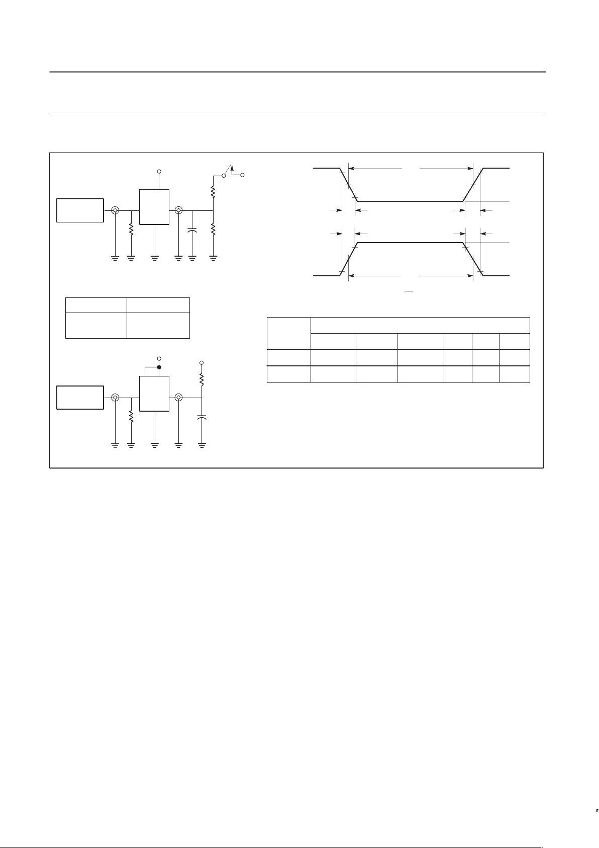
TEST CIRCUIT AND WAVEFORMS
2.5ns
2.0ns500ns
500ns
INPUT PULSE REQUIREMENTS
Rep. RateAmplitude t
TLHtTHL
1MHz3.0V
2.5ns
Input Pulse Definitions
VM = 1.55V for Bn, VM = 1.5V for all others.
V
CC
Family
FB+
D.U.T.
PULSE
GENERATOR
7.0V
R
L
R
L
C
L
R
T
V
IN
V
OUT
Test Circuit for 3-State Outputs on A Port
TEST SWITCH
SWITCH POSITION
t
PLZ,
t
PZL
All other
closed
open
DEFINITIONS:
RL= Load Resistor; see AC CHARACTERISTICS for value.
CL= Load capacitance includes jig and probe capacitance; see AC
CHARACTERISTICS for value.
R
T
= Termination resistance should be equal to Z
OUT
of pulse generators.
CD= Load capacitance includes jig and probe capacitance; see AC
CHARACTERISTICS for value.
RU= Pull up resistor; see AC CHARACTERISTICS for value.
t
W
90%
V
M
10%
90%
V
M
10%
90%
V
M
10%
90%
V
M
10%
NEGATIVE
PULSE
POSITIVE
PULSE
AMP (V)
LOW V
LOW V
t
THL
(tf)
t
TLH
(tr)
t
W
t
W
Low V
0.0V
t
TLH
(tr)
t
THL
(tf)
AMP (V)
A Port
1MHz2.0V
2.0ns
1.0VB Port
V
CC
D.U.T.
PULSE
GENERATOR
R
U
C
D
R
T
V
IN
V
OUT
Test Circuit for Outputs on B Port
BIAS
V
2.0V (for RU = 9 Ω)
2.1V (for RU = 16.5 Ω)
SG00063
Page 13
Philips Semiconductors Product specification
FBL22033
3.3V BTL 8-bit latched/registered/pass-thru
Futurebus+ universal interface transceiver
1999 Apr 15
13
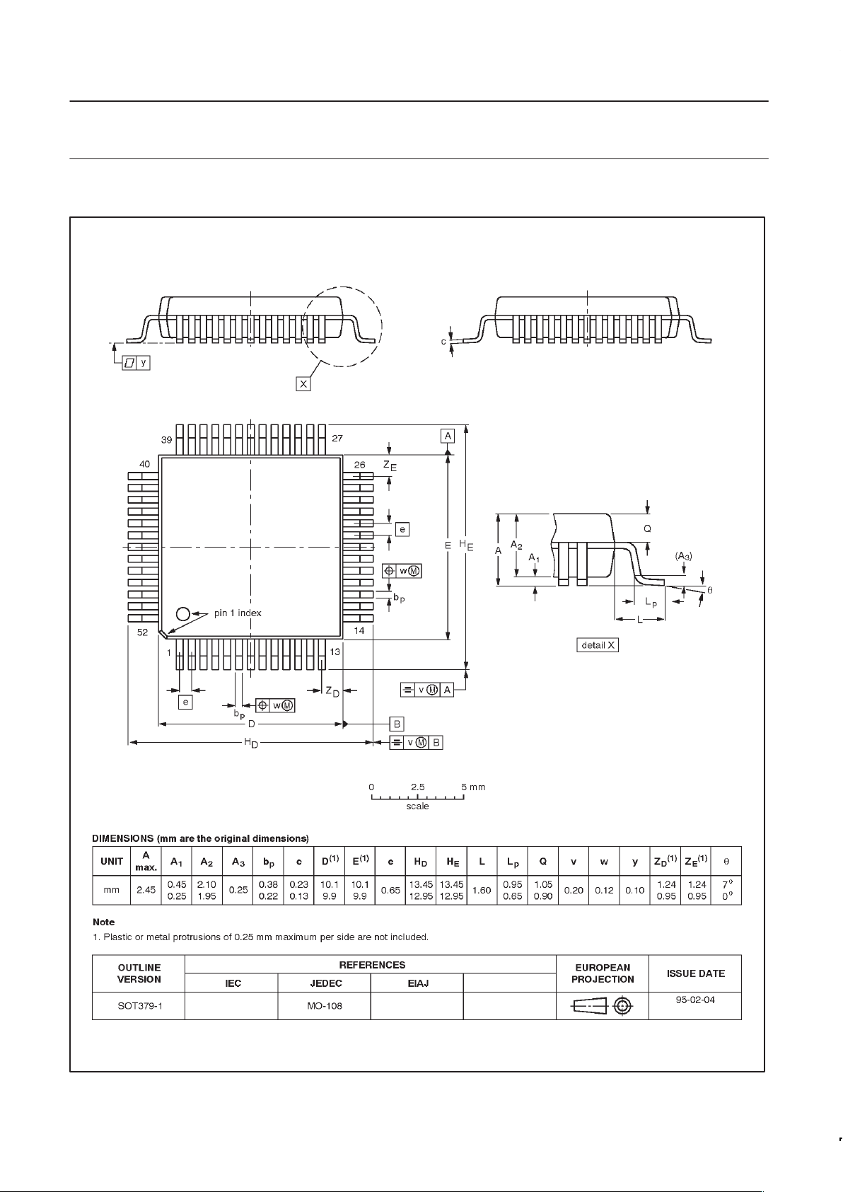
QFP52: plastic quad flat package; 52 leads (lead length 1.6 mm); body 10 x 10 x 2.0 mm SOT379-1
Page 14

Philips Semiconductors Product specification
FBL22033
3.3V BTL 8-bit latched/registered/pass-thru
Futurebus+ universal interface transceiver
yyyy mmm dd
14
Definitions
Short-form specification — The data in a short-form specification is extracted from a full data sheet with the same type number and title. For
detailed information see the relevant data sheet or data handbook.
Limiting values definition — Limiting values given are in accordance with the Absolute Maximum Rating System (IEC 134). Stress above one
or more of the limiting values may cause permanent damage to the device. These are stress ratings only and operation of the device at these or
at any other conditions above those given in the Characteristics sections of the specification is not implied. Exposure to limiting values for extended
periods may affect device reliability.
Application information — Applications that are described herein for any of these products are for illustrative purposes only. Philips
Semiconductors make no representation or warranty that such applications will be suitable for the specified use without further testing or
modification.
Disclaimers
Life support — These products are not designed for use in life support appliances, devices or systems where malfunction of these products can
reasonably be expected to result in personal injury . Philips Semiconductors customers using or selling these products for use in such applications
do so at their own risk and agree to fully indemnify Philips Semiconductors for any damages resulting from such application.
Right to make changes — Philips Semiconductors reserves the right to make changes, without notice, in the products, including circuits, standard
cells, and/or software, described or contained herein in order to improve design and/or performance. Philips Semiconductors assumes no
responsibility or liability for the use of any of these products, conveys no license or title under any patent, copyright, or mask work right to these
products, and makes no representations or warranties that these products are free from patent, copyright, or mask work right infringement, unless
otherwise specified.
Philips Semiconductors
811 East Arques Avenue
P.O. Box 3409
Sunnyvale, California 94088–3409
Telephone 800-234-7381
Copyright Philips Electronics North America Corporation 1998
All rights reserved. Printed in U.S.A.
print code Date of release: 07-98
Document order number: 9397-750-05518
Data sheet
status
Objective
specification
Preliminary
specification
Product
specification
Product
status
Development
Qualification
Production
Definition
[1]
This data sheet contains the design target or goal specifications for product development.
Specification may change in any manner without notice.
This data sheet contains preliminary data, and supplementary data will be published at a later date.
Philips Semiconductors reserves the right to make chages at any time without notice in order to
improve design and supply the best possible product.
This data sheet contains final specifications. Philips Semiconductors reserves the right to make
changes at any time without notice in order to improve design and supply the best possible product.
Data sheet status
[1] Please consult the most recently issued datasheet before initiating or completing a design.
 Loading...