

Page 1
Vicor Corp. Tel: 800-735-6200, 978-470-2900 Fax: 978-475-6715 FasTrak Maxi E-Grade Family Rev. 1.1 Page 1 of 8
Set your site on VICOR at www.vicorpower.com
4.6 x 2.2 x 0.5 in
117 x 56 x 12,7 mm
45
Absolute Maximum Ratings
Parameter Min Typ Max Unit
Baseplate to sink; flat, greased surface 0.08 °C/Watt
Baseplate to sink; thermal pad (P/N 20263) 0.07 °C/Watt
Baseplate to ambient 4.9 °C/Watt
Baseplate to ambient; 1000 LFM 1.1 °C/Watt
Thermal capacity 165 Watt-sec/°C
Thermal Resistance and Capacity
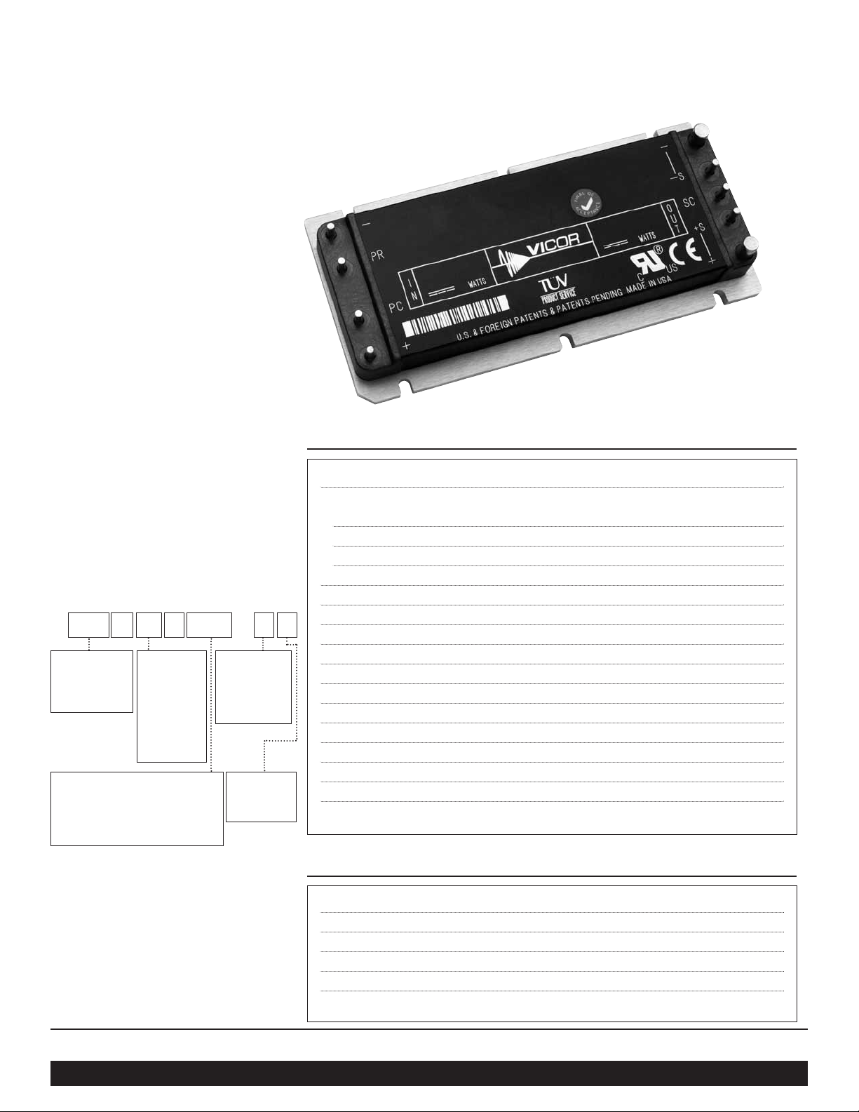
Data Sheet
FasTrak Maxi E-Grade Family
DC-DC Converter Module
Features
• Input voltages: 24, 48, 300 & 375 V
• DC outputs: 2 V – 48 V
• Programmable output: 10 to 110%
• Regulation: ±0.5% no load to full load
• Efficiency: Up to 90%
• Max operating temp: 100°C, full load
• Power density: Up to 120 W/cubic inch
• Parallelable, with N+M fault tolerance
• Low noise ZCS/ZVS architecture
Product Overview
These DC-DC converter modules use
advanced power processing, control and
packaging technologies to provide the
performance, flexibility, reliability and
cost effectiveness of a mature power
component. High frequency ZCS/ZVS
switching provide high power density
with low noise and high efficiency.
Applications
Off-line systems with autoranging or
PFC frontends, industrial and process
control, distributed power, medical, ATE,
communications, defense, aerospace
Part Numbering
e.g. V300A12E500BL2
For a description of pin options, see page 6.
Baseplate options include slotted flanges,
threaded and through-hole. See page 7 for
dimensions. For other package sizes and
power levels, see the FasTrak Mini (half
size) and FasTrak Micro (quarter size)
datasheets.
Parameter Rating Unit Notes
+In to –In voltage
24 Vin -0.5 to +36 Vdc
48 Vin -0.5 to +75 Vdc
300 Vin -0.5 to +375 Vdc
375 Vin -0.5 to +425 Vdc
PC to –In voltage -0.5 to +7.0 Vdc
PR to –In voltage -0.5 to +7.0 Vdc
SC to –Out voltage -0.5 to +1.5 Vdc
–Sense to –Out voltage 1.0 Vdc
Isolation voltage (in to out) 3000 Vrms
Isolation voltage (in to base) 1550 Vrms
Isolation voltage (out to base) 500 Vrms
Operating temperature -10 to +100 °C
Storage temperature -20 to +125 °C
Pin soldering temperature 500 (260) °F (°C) <5 sec; wave solder
Pin soldering temperature 750 (390) °F (°C) <7 sec; hand solder
Mounting torque 5 (0.57) in-lbs (N-m) 6 each, # 4-40 or M3
VAE B
Input Voltage
24: 18 – 36 Vin
48: 36 – 75 Vin
300: 180 – 375 Vin
375: 250 – 425 Vin
Output Voltage
2: 2.0 V*
3V3: 3.3V
5: 5 V
12: 12 V
15: 15 V
24: 24 V
28: 28 V
48: 48 V
54: 54 V**
Pin Style
Blank: Short
Tin/Lead
L: Long Tin/Lead
S: Short Gold
N: Long Gold
Output Power (Watts)
Input 2 Vout 3.3 Vout 5 Vout >5 Vout
24 V – 264 400 400
48 V – 264 400 500
300 V 160 264 400 500
375 V – 264 400 600
Baseplate
Blank: Slotted
1: Threaded
2: Through-hole
* 300 V input only
** 375 V input only
Page 2
Vicor Corp. Tel: 800-735-6200, 978-470-2900 Fax: 978-475-6715 FasTrak Maxi E-Grade Family Rev. 1.1 Page 2 of 8
Set your site on VICOR at www.vicorpower.com
Parameter 2V 3.3V 5V 12V 15V 24V 28V 48V 54V Unit Notes
Efficiency (typ.) 73.5 80.0 83.5 85.5 87.0 88.0 89.0 90.0 89.6 % Nominal input; 80% load; 25°C
Ripple and noise, p-p (typ.) 75 60 70 130 90 80 65 50 160 mV
Nominal input; full load;
25°C; 20 MHz BW
Output OVP setpoint (nom.) 2.8 4.3 6.3 14.3 17.8 28.1 32.7 55.7 62.6 Volts
25°C; recycle input voltage to
restart ( 1 minute off )
Dissipation, standby (typ.) 4.8 5.6 6.2 8.0 8.0 6.0 7.4 8.5 6.0 Watts No load; nominal input
Load regulation (max.) 0.5 0.5 0.5 0.5 0.5 0.5 0.5 0.5 0.5 ±% Vout No load to full load; nominal input
Current limit (typ.) 125 125 125 125 125 125 125 125 125 % Iout Output voltage 95% of nominal
Short circuit current (typ.) 125 125 125 125 125 125 125 125 125 % Iout Output voltage <250 mV
Parameter Min Typ Max Surge Withstand Unit Notes
Input voltage
24 Vin 18 24 36 50 Vdc <100 ms surge withstand
48 Vin 36 48 75 100 Vdc
300 Vin 180 300 375 400 Vdc
375 Vin 250 375 425 500 Vdc
Output voltage setpoint ±1 % Nominal input; full load; 25°C
Parameter Min Typ Max Unit Notes
Line regulation ±0.5 % Low line to high line; full load
Temperature regulation ±0.005 % / °C Over operating temperature range
Power sharing accuracy ±5 % 10 to 100% of full load
Programming range 10 110 %
Of nominal output voltage. For trimming below
90% of nominal, a minimum load of 10% of
maximum rated power may be required.
Parameter 24 Vin 48 Vin 300 Vin 375 Vin Units Notes
Undervoltage turn-on 17.5 34.9 175 243 Vdc Typical value
Undervoltage turn-off 15.3 30.5 153 212 Vdc Typical value
Overvoltage turn-off/on 37.8 78.8 N/A 446 Vdc Typical value
MODULE OPERATING SPECIFICATIONS
MODULE INPUT SPECIFICATIONS
MODULE OUTPUT SPECIFICATIONS
ELECTRICAL CHARACTERISTICS
Electrical characteristics apply over the full operating range of input voltage, output load (resistive) and baseplate temperature,
unless otherwise specified. All temperatures refer to the operating temperature at the center of the baseplate.
MODULE OUTPUT VOLTAGE RELATED SPECIFICATIONS
Note: For important information relative to applications where the converter modules are subject to continuous dynamic loading,
contact Vicor applications engineering at 800-927-9474.
Note: 300 Vin models do not have overvoltage turn-off.
Page 3

Vicor Corp. Tel: 800-735-6200, 978-470-2900 Fax: 978-475-6715 FasTrak Maxi E-Grade Family Rev. 1.1 Page 3 of 8
Set your site on VICOR at www.vicorpower.com
Parameter Min Typ Max Unit Notes
PRIMARY SIDE
(PC = Primary Control; PR = Parallel)
PC bias voltage 5.50 5.75 6.00 Vdc PC current = 1.0 mA
current limit 1.5 2.1 3.0 mA PC voltage = 5.5V
PC module disable 2.3 2.6 2.9 Vdc Must be able to sink ≥4 mA. See Fig. 1
PC module enable delay 4 7 ms
PC module alarm 0.5 Vavg UV, OV, OT, module fault. See Figs. 2 and 4
PR emitter amplitude 5.7 5.9 6.1 Volts PR load >30 ohms, < 30 pF
PR emitter current 150 mA
PR receiver impedance 375 500 625 ohms 25°C
PR receiver threshold 2.4 2.5 2.6 Volts Minimum pulse width: 20ns
PR drive capability 12 modules Without PR buffer amplifier
SECONDARY SIDE
(SC = Secondary Control)
SC bandgap voltage 1.21 1.23 1.24 Vdc Referenced to –Sense
SC resistance 990 1000 1010 ohms
SC capacitance 0.033 µF
SC module alarm 0 Vdc With open trim; referenced to –Sense. See Fig. 6
Parameter Min Typ Max Unit Notes
Remote sense (total drop) 0.5 Vdc 0.25V per leg (senses must be closed)
Isolation voltage (in to out) 3000 Vrms Complies with reinforced insulation requirements
Isolation voltage (in to base) 1550 Vrms Complies with basic insulation requirements
Isolation voltage (out to base) 500 Vrms Complies with operational insulation requirements
Isolation resistance (in to out) 10 megohms
Weight 7.3 (210) 8 (227) ounces (grams)
Temperature limiting 100 115 °C See Figs. 2 and 4
Agency approvals cULus, TÜV, CE
UL60950, EN60950, CSA60950, IEC60950.
With a fuse in series with the +Input
MODULE CONTROL SPECIFICATIONS
MODULE GENERAL SPECIFICATIONS
ELECTRICAL CHARACTERISTICS, continued
Note:
Specifications are subject to change without notice.
The latest data sheets for individual models are available on the Vicor website at vicorpower.com.
Page 4

Vicor Corp. Tel: 800-735-6200, 978-470-2900 Fax: 978-475-6715 FasTrak Maxi E-Grade Family Rev. 1.1 Page 4 of 8
Set your site on VICOR at www.vicorpower.com
CONTROL FUNCTIONS - PC PIN
Module Enable/Disable
The module may be disabled by pulling PC below 2.3V with
respect to the –Input. This may be done with an open collector
transistor, relay, or optocoupler. Multiple converters may be
disabled with a single transistor or relay either directly or via
“OR’ing” diodes. See Figure 1.
Module Alarm
The module contains “watchdog” circuitry which monitors
input voltage, operating temperature and internal operating
parameters. In the event that any of these parameters are
outside of their allowable operating range, the module will shut
down and PC will go low. PC will periodically go high and the
module will check to see if the fault (as an example,
overtemperature) has cleared. If the fault has not been cleared,
PC will go low again and the cycle will restart. The SC pin will
go low in the event of a fault and return to its normal state after
the fault has been cleared. See Figures 2 and 4.
+In
PC
PR
–In
Disable
Disable = PC <2.3V
Figure 1—Module enable/disable.
Figure 3—LED on-state indicator.
+In
PC
PR
–In
4kΩ
"Module
Enabled"
+In
PC
PR
–In
Optocoupler
4kΩ
Alarm
1.00V
+Out
+S
SC
–S
–Out
Figure 2—PC/SC module alarm logic.
Figure 5—Isolated on-state indicator.
2-20ms typ.
Fault
SC
PC
1.23V
5.7V
40μs typ.
Figure 4—PC/SC module alarm timing.
Figure 6—Secondary side on-state indicator.
Primary Auxiliary Supply
At 5.7V, PC can source up to 1.5mA. In the example shown in
Figure 3, PC powers a module enabled LED.
Input Undervoltage
+In
PC
PR
–In
SW1
Auto
Restart
2-20ms typ.
f (VIN)
SW1, 2, & 3
shown in
"Fault" position
5.7Vdc
(0-3mA)
Input Overvoltage
Overtemperature
Module Faults
50Ω
SW2
SW3
1.23
Vdc
1K
6K
+Out
+S
SC
–S
–Out
Page 5

Vicor Corp. Tel: 800-735-6200, 978-470-2900 Fax: 978-475-6715 FasTrak Maxi E-Grade Family Rev. 1.1 Page 5 of 8
Set your site on VICOR at www.vicorpower.com
Output Voltage Programming
The output voltage of the converter can be adjusted or
programmed via fixed resistors, potentiometers or voltage
DACs. See Figures 7 and 8.
CONTROL FUNCTIONS - SC PIN
Figure 8—Output voltage trim up circuit.Figure 7—Output voltage trim down circuit.
RD (ohms) =
1,000 Vout
Vnom - Vout
+Out
+S
SC
–S
–Out
R
U
Trim Up
Load
Error
Amp
1kΩ
1.23V
0.033μF
Load
+Out
+S
SC
–S
–Out
R
D
Trim Down
Error
Amp
1kΩ
1.23V
0.033μF
Trim Down
1. This converter is not a constant power device – it has a
constant current limit. Hence, available output power is
reduced by the same percentage that output voltage is
trimmed down. Do not exceed maximum rated output current.
2. The trim down resistor must be connected to the –Sense pin.
Trim Up
1. The converter is rated for a maximum delivered power. To ensure
that maximum rated power is not exceeded, reduce maximum
output current by the same percentage increase in output voltage.
2. The trim up resistor must be connected to the +Sense pin.
3. Do not trim the converter above maximum trim range
(typically +10%) or the output over voltage
protection circuitry may be activated.
RU (ohms) =
1,000 (Vout-1.23) Vnom
–
1,000
1.23 (Vout-Vnom)
Trim resistor values calculated automatically:
On-line calculators for trim resistor values are available
on the vicor website at: vicorpower.com/tools.html.
Resistor values can be calculated for fixed trim up, fixed
trim down and for variable trim up or down cases for both
1st and 2nd Generation DC-DC converters.
In addition to trimming information, the web site and the
Applications Manual also include design tips, applications
circuits, EMC suggestions, thermal design guidelines and
PDF data sheets for all available Vicor products.
Page 6

Vicor Corp. Tel: 800-735-6200, 978-470-2900 Fax: 978-475-6715 FasTrak Maxi E-Grade Family Rev. 1.1 Page 6 of 8
Set your site on VICOR at www.vicorpower.com
+Out
+S
SC
–S
–Out
+Sense from
other modules
in the array
Figure 12—OR’ing diodes connections.
Module 2
Module 1
Module N+1
+Out
+S
SC
–S
–Out
+Out
+S
SC
–S
–Out
+Out
+S
SC
–S
–Out
Load
+S
–S
+S
–S
+S
–S
Figure 11—N+1 module array output connections.
• The +Out and –Out power buses should be
designed to minimize and balance parasitic
impedance from each module output to the load.
• The +Sense pins should be tied to the same
point on the +Out power bus; the –Sense pins
should be tied to the same point on the –Out
power bus.
• At the discretion of the power system designer,
a subset of all modules within an array may be
configured as slaves by shorting SC to –S.
• OR’ing diodes may be inserted in series with
the +Out pins of each module to provide
module output fault tolerance.
CONTROL FUNCTIONS - PR PIN
Parallel Operation
The PR pin supports paralleling for increased power with N+1
(N+M) redundancy and phased array capability. Modules of
the same input voltage, output voltage, and power level will
current share if all PR pins are suitably interfaced.
Compatible interface architectures include the following:
DC coupled single-wire interface. All PR pins are directly
connected to one another. This interface supports current
sharing but is not fault tolerant. Minus In pins must be tied to
the same electric potential. See Figure 9.
AC coupled single-wire interface. All PR pins are connected
to a single communication bus through 0
.001µF (500V)
capacitors. This interface supports current sharing and is fault
tolerant except for the communication bus. See Figure 10.
Figure 9—DC coupled single-wire interface.
+In
PC
PR
–In
Module 2
(up to 12)
+In
PC
PR
–In
Module 1
Ground plane
+In
PC
PR
–In
Module 2
(up to 12)
+In
PC
PR
–In
Module 1
Ground plane
Figure 10—AC coupled single-wire interface.
0.001µF
0.001µF
PIN STYLES
*
Designator Description Notes
(None) Short solder Requires in-board, mounting
L Long solder On-board mounting for 0.065" boards
S Short ModuMate SurfMate or in-board socket mounting – RoHS compliant
N Long ModuMate On-board socket mounting – RoHS compliant
* Pin style designator follows the “B” after the output power and precedes the baseplate designator.
Ex. V375A24C600BN — Long ModuMate Pins
Page 7

Vicor Corp. Tel: 800-735-6200, 978-470-2900 Fax: 978-475-6715 FasTrak Maxi E-Grade Family Rev. 1.1 Page 7 of 8
Set your site on VICOR at www.vicorpower.com
MECHANICAL DRAWINGS
0.195
4,95
1.400*
35,56
1.000*
25,40
0.700*
17,78
0.400*
10,16
3.844
97,64
4.200*
106,68
1.790
45,47
0.06
1,5
R (4X)
0.178
4,52
56789
12 34
±0.003
±0,08
* DENOTES
TOL =
PLATED
THRU HOLE
DIA
PCB THICKNESS
0.062 ±0.010
1,57 ±0,25
SHORT PIN STYLE
0.094 ±0.003
2,39 ±0,08
0.194 ±0.003
4,93 ±0,08
LONG PIN STYLE
0.094 ±0.003
2,39 ±0,08
0.194 ±0.003
4,93 ±0,08
INBOARD
SOLDER
MOUNT
0.43
10,9
ONBOARD
SOLDER
MOUNT
(7X)
(2X)
0.53
13,5
PCB MOUNTING SPECIFICATIONS
1.74
44,2
2.20
55,9
56789
4321
0.23
5,8
(REF)
0.180
4,57
0.080
2,03
1.400
35,56
1.000
25,40
0.700
17,78
0.400
10,16
DIA,(7X)
DIA,(2X)
4-40 UNC-2B
Thru (4X)***
(Style 2 and 3 only)
Slotted
or
Threaded
4-40 UNC-2B (6X)
or
Thru Hole
#30 Drill Thru (6X)
(0.1285)
0.50
12,7
0.06
1,5
2.20
55,9
(REF)
1.80
45,7
4.60
116,8
3.60
91,4
0.13
3,3
FULL R (6X)
(6X)
R (3X)
CHAMFER
0.15
3,81
X 45°
0.54
13,7
0.43
10,9
0.38
9,6
0.20**
5,08
0.12*
3,1
(2X)
0.01
Use a
4-40 Screw (6x)
Torque to:
5 in-lbs
0.57 N-m
Long Pin
0.62
15,7
Short Pin
(9X)
(9X)
(ALL MARKINGS THIS SURFACE)
ALUMINUM
BASEPLATE
0.50 ±0.02
12,7 ±0,5
* Style 1 baseplate only
** Style 2 & 3 baseplates
*** Reserved for Vicor accessories. Not for mounting
Center line
4.200
106,68
0.300±0.015
7,62±0,38
0.300±0.015
7,62±0,38
2.00
50,8
0.10
2,5
Pin C
L
Pin C
L
C
L
Converter Pins
No. Function Label
1 +In +
2
Primary
PC
Control
3 Parallel PR
4 –In –
5 –Out –
6 –Sense –S
7
Secondary
SC
Control
8 +Sense +S
9+Out +
MODULE OUTLINE
ALL MARKINGS
THIS SURFACE
ALUMINUM
BASEPLATE
PINS STYLES
SOLDER:TIN/LEAD
HOT SOLDER DIPPED
MODUMATE: GOLD PLATED COPPER
Page 8

Vicor Corp. Tel: 800-735-6200, 978-470-2900 Fax: 978-475-6715 FasTrak Maxi E-Grade Family Rev. 1.1 11/05
Set your site on VICOR at www.vicorpower.com
Vicor’s comprehensive line of power solutions includes modular, high
density DC-DC converters and accessory components, configurable power
supplies, and custom power systems.
Information furnished by Vicor is believed to be accurate and reliable. However, no responsibility is
assumed by Vicor for its use. No license is granted by implication or otherwise under any patent or patent
rights of Vicor. Vicor components are not designed to be used in applications, such as life support systems,
wherein a failure or malfunction could result in injury or death. All sales are subject to Vicor’s Terms and
Conditions of Sale, which are available upon request.
Specifications are subject to change without notice.
Vicor Corporation
25 Frontage Road
Andover, MA, USA 01810
Tel: 800-735-6200
978-470-2900
Fax: 978-475-6715
Email
Vicor Express: vicorexp@vicr.com
Technical Support: apps@vicr.com
Component Solutions
for Your Power System
45
 Loading...