

Page 1
tm
FAN5611/FAN5612/FAN5613/FAN5614
Low-Dropout LED Drivers for White, Blue,
or any Color LED
Low-Dropout LED Drivers for White, Blue, or any Color LED
November 2006
Features
■ LED drivers for parallel-connected LEDs (2 to 4)
■ Ultra-low voltage drop (< 300mV) to support direct
Li-ion applications
■ No EMI, no switching noise
■ No external components needed for current matching
■ Both analog and PWM brightness control
■ FAN5611, FAN5613 feature up to 160mA bias current
(up to 40mA for each LED)
■ FAN5612 features up to 120mA bias current
(up to 40mA for each LED)
■ FAN5614 features up to 160mA bias current
(up to 80mA for each LED)
■ Enable/Shutdown control (FAN5612, FAN5613,
FAN5614)
■ Shutdown current < 1μA
■ Small footprint SC-70 and MLP
Applications
■ Cell Phones
■ PDA, DSC, MP3 Players
■ Handheld Computers
■ LCD Display Modules
■ Keyboard Backlight
■ LED Displays
Description
The FAN5611/12/13/14 low-dropout product family is
designed to drive two to four parallel LEDs, providing
matched current source bias for all color LEDs. The LED
current is set by an external resistor, R
FAN5611/13 supports four parallel LEDs with up to
160mA bias current (up to 40mA per output). The
FAN5612 supports three LEDs with up to 120mA bias
current (40mA per output). The FAN5614 drives two
high-current LEDs (80mA per output). Pin I1 should
always be connected to an LED to provide a matched
current for any additional LEDs.
The FAN5612/13 and 14 are selected using an ENABLE
pin. When the chip is not selected (ENABLE pin is
LOW), the supply current drops to less than 1µA.
The FAN5611, FAN5612, and FAN5614 are available in
an SC-70 package. The FAN5611 and FAN5613 are
available in MLP packages.
SET
. The
Ordering Information
Product Number Package Type Order Code
FAN5611 6-Lead SC-70 / 2x2mm 6-Lead MLP FAN5611S7X / FAN5611MPX
FAN5612 6-Lead SC-70 FAN5612S7X
FAN5613 2x2mm 8-Lead MLP FAN5613MPX
FAN5614 6-Lead SC-70 FAN5614S7X
Table 1. Ordering Information
© 2003 Fairchild Semiconductor Corporation www.fairchildsemi.com
FAN5611/FAN5612/FAN5613/FAN5614 Rev. 1.0.9
Page 2
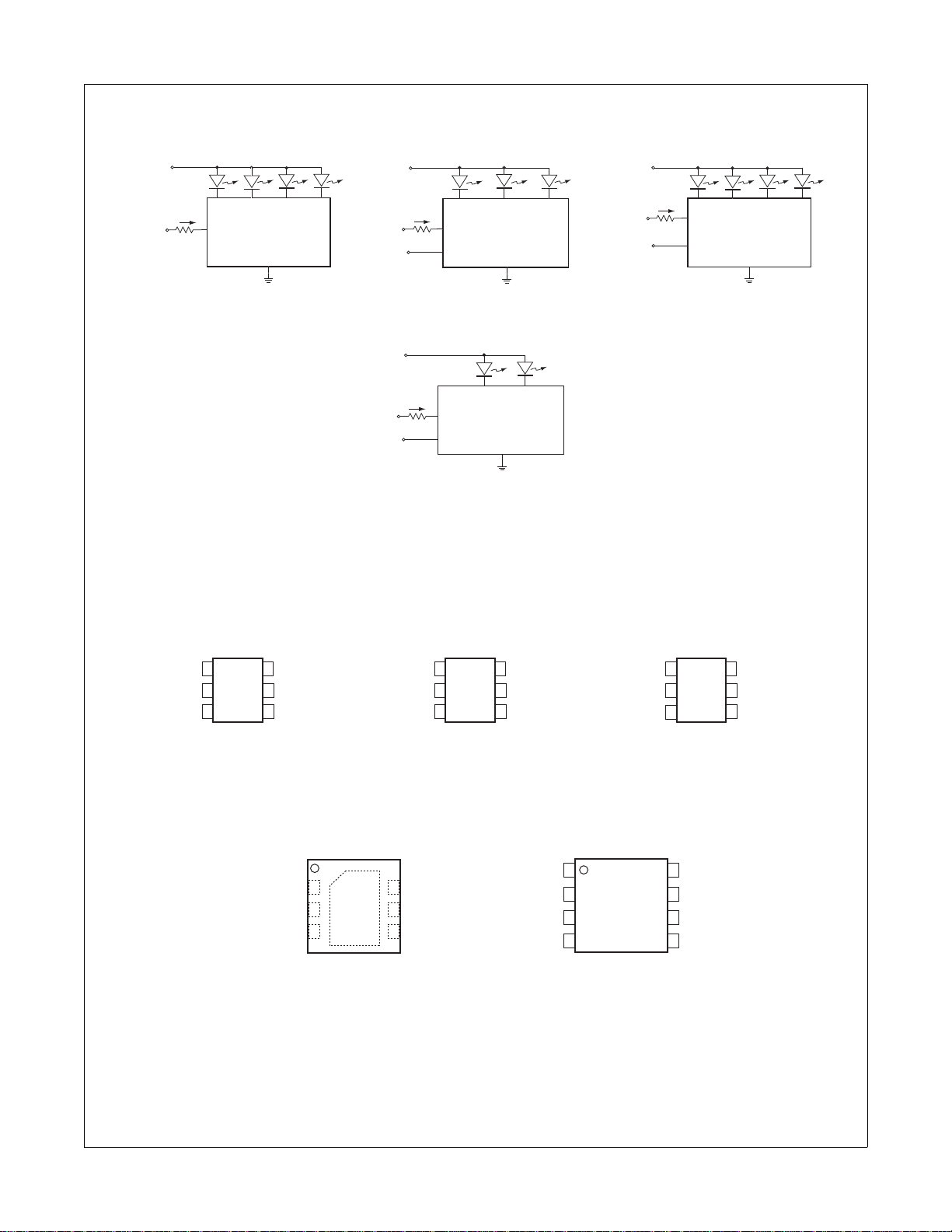
Typical Applications
FAN5611/FAN5612/FAN5613/FAN5614
V
IN
I
V
CONTROL
SET
(3V
)
CTRL
R
SET
Four Diode Control
Figure 1. Typical Applications for FAN5611, FAN5612, FAN5613, FAN5614
Pin Assignments
FAN5611
GND
CONTROL
V
IN
I
SET
(3V)
R
SET
ENABLE
I3
FAN5613
GND
I2
I1
I4
CTRL
ON/OFF
Four Diode Control With ON/OFF
V
IN
I1I2I3I4
V
(3V)
CONTROL
ENABLE
V
IN
V
CONTROL
I
(3V)
R
ENABLE
I3
I
SET
CTRL
R
SET
ON/OFF
Three Diode Control with ON/OFF
SET
CTRL
SET
ON/OFF
Two Diode Control with ON/OFF
I2
FAN5612
GND
FAN5614
GND
I1
I3/I4I1/I2
V
CTRL
I2
I1
FAN5611
1
6
25
4
3
I3
I4
GND
CTRL
I2
I1
1
6
25
34
ON/OFF
I3
GND
I1/I2
FAN5612
6-LEAD SC-70
TOP VIEW
ON/OFF
D2
CTRL
D3
GND
D1
GND
D4
GND
FAN5611
2x2mm 6-LEAD MPX
Figure 2. Pin Assignments for FAN5611, FAN5612, FAN5613, FAN5614
2x2mm 8-LEAD MLP
TOP VIEW
I3
I4
FAN5613
N/C
1
6
25
34
FAN5614
NC
CTRL
I2
I1
ON/OFFCTRL
I3/I4
GND
© 2003 Fairchild Semiconductor Corporation www.fairchildsemi.com
FAN5611/FAN5612/FAN5613/FAN5614 Rev. 1.0.9 2
Page 3
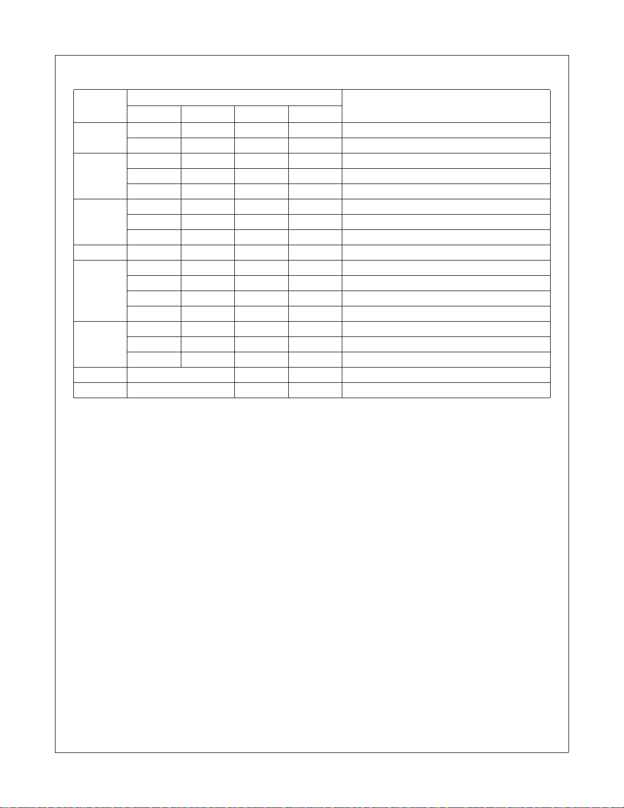
Pin Descriptions
Name
Pin #
1 CTRL CTRL CTRL Sets LED Current (see Operational Descripton)
ON/OFF Chip ON/OFF/Disable
2 I2 I2 Connect to Cathode of LED
I3 Connect to Cathode of LED
I1/I2
3 I1 I1 Connect to Cathode of LED
I4 Connect to Cathode of LED
N/C No Connection
4GNDGNDGNDGNDGround
5 I4 Connect to Cathode of LED
I3 Connect to Cathode of LED
I1 Connect to Cathode of LED
I3/I4 Connect to Cathode of LED
6 I3 Connect to Cathode of LED
ON/OFF ON/OFF Chip ON/OFF/Disable
I2 Connect to Cathode of LED
7 CTRL Sets LED Current (see Operational Descripton)
8 NC No Connection
Table 2. Pin Descriptions
DescriptionFAN5611 FAN5612 FAN5613 FAN5614
FAN5611/FAN5612/FAN5613/FAN5614
Notes:
1. The DAP of FAN 5611MPX can be tied to the GND pin or left floating. For better power dissipation, tie to GND.
© 2003 Fairchild Semiconductor Corporation www.fairchildsemi.com
FAN5611/FAN5612/FAN5613/FAN5614 Rev. 1.0.9 3
Page 4
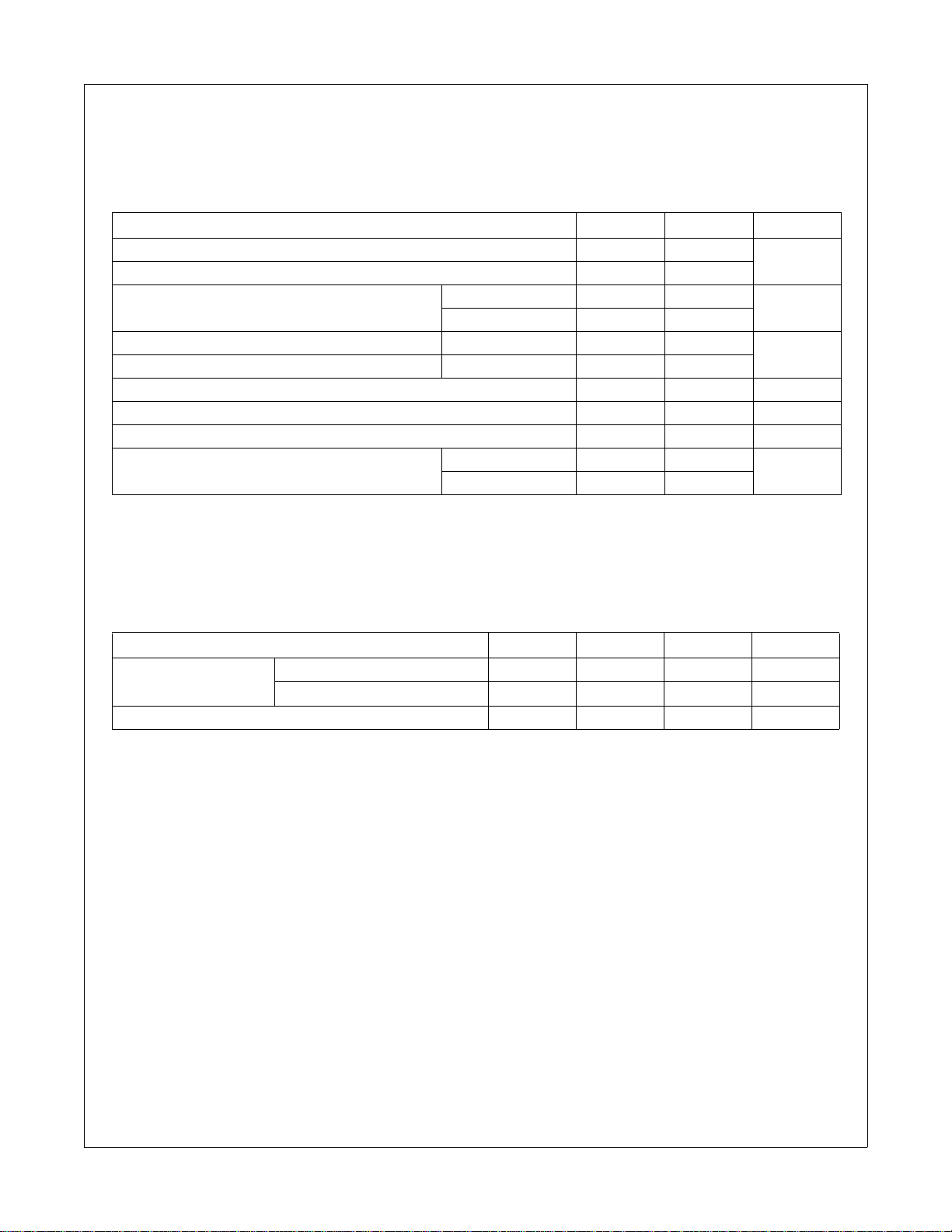
Absolute Maximum Ratings
The “Absolute Maximum Ratings” are those values beyond wh ich the safety o f the device cannot be guaranteed. The
device should not be operated at these limits. The parametric values defined in the Electrical Characteristics tables are
not guaranteed at the absolute maximum ratings. The “R ecommended Operating Cond itions” table defines the conditions for actual device operation.
Parameter Min. Max. Unit
VI1, VI2, VI3, VI4 and ENABLE Voltage to GND -0.3 6.0 V
CTRL Voltage to GND -0.3 3.0
Power Dissipated by package at T
I1, I2, I3, I4 Steady State Current FAN5611/12/13 40 mA
I1/I2, I3/I4 Steady State Current FAN5614 80
Lead Temperature (Soldering 10 seconds) 300 °C
Junction Temperature 150 °C
Storage Temperature -55 150 °C
Electrostatic Discharge Protection (ESD) Level
Table 3. Absolute Maximum Ratings
= 85°C 6-Lead SC70 190 mW
A
6, 8-Lead MLP 700
(1)
HBM 4 kV
CDM 1
FAN5611/FAN5612/FAN5613/FAN5614
Recommended Operating Conditions
Parameter Min. Typ. Max. Unit
LED Cathode Voltage FAN5611, FAN5612, FAN5613 0.3 0.5 1.0 V
FAN5614 0.15
Ambient Temperature -40 25 85 °C
T able 4. Recommended Operating Conditions
Notes:
2. Using Mil Std. 883E, method 3015.7 (Human Body Model) and EIA/JESD22C101-A (Charge Device Model).
© 2003 Fairchild Semiconductor Corporation www.fairchildsemi.com
FAN5611/FAN5612/FAN5613/FAN5614 Rev. 1.0.9 4
Page 5
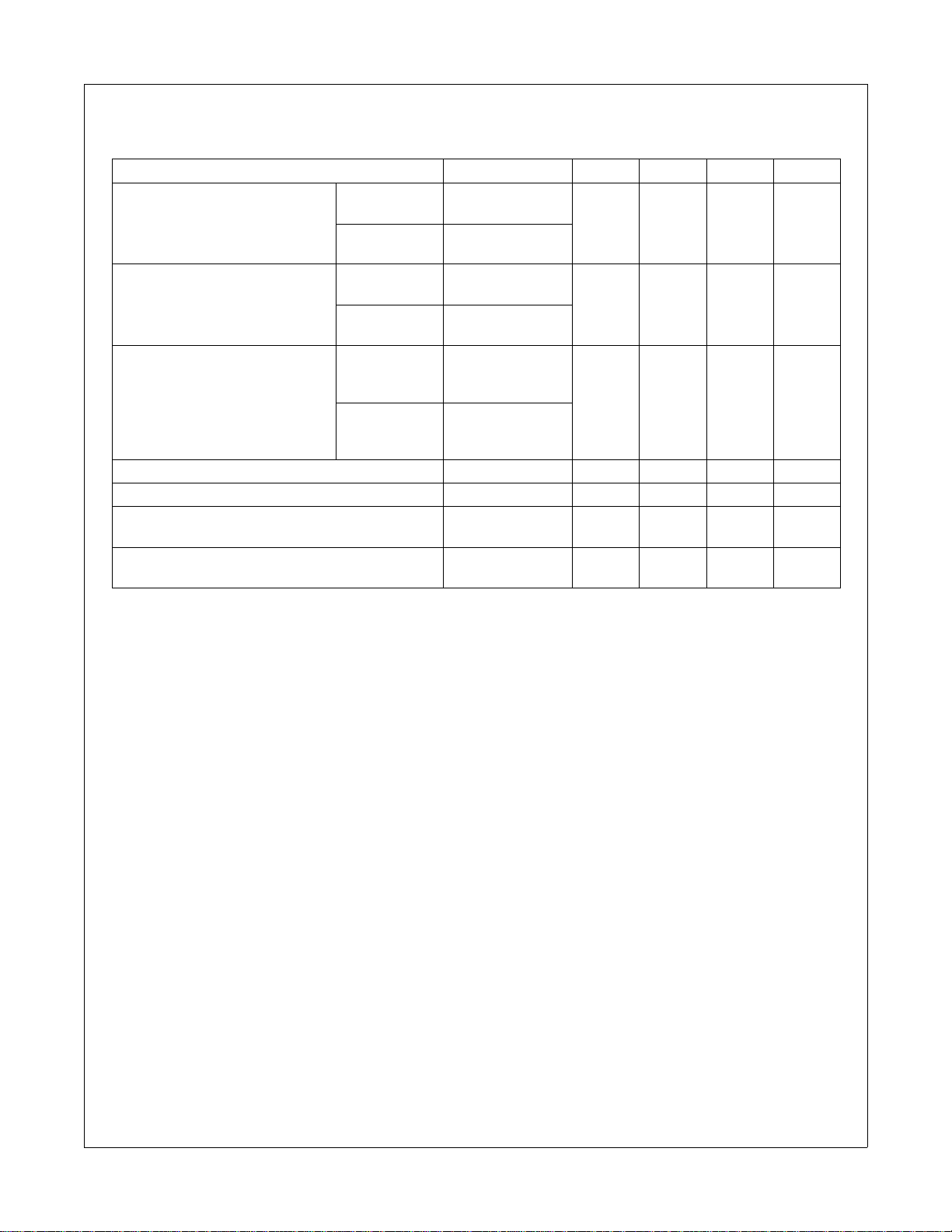
DC Electrical Characteristics
VIN = 3.3V to 5.5V, ENABLE = VIN, TA = 25°C unless otherwise noted.
Parameter Conditions Min. Typ. Max. Units
= 100µA
I
FAN5611/12/13
Current Gain
FAN5614
LED Current (Per Diode)
FAN5611/12/13
FAN5614
FAN5611/12/13
LED to LED Current Matching
FAN5614
Peak Efficiency V
Current in OFF Mode (I
Minimum ENABLE “ON Voltage”
and II)V
SET
(2)
(FAN5612, FAN5613, FAN5614)
Maximum ENABLE “OFF Volt age”
(2)
(FAN5612, FAN5613 FAN5614)
Table 5. DC Electrical Characteristics
Notes:
3. ENABLE “ON” is V
where II1>20mA @ VI1=0.3V, while ENABLE “OFF” is V
EN
SET
V
= 300mV
SAT
I
= 100µA
SET
V
= 150mV
SAT
= 300mV
V
SAT
I
= 100µA
SET
= 150mV
V
SAT
= 100µA
I
SET
V
= 300mV
SAT
I
= 100µA
SET
TA = -40°C to 85°C
V
= 150mV
SAT
= 100µA
I
SET
TA = -40°C to 85°C
= 3V 90 %
IN
= 0V 1 µA
EN
I
= 150µA 2.8 V
SET
140 200 260
20 mA
-3 3
0.5 V
where II1<1μA @ VI1>0.3V.
EN
FAN5611/FAN5612/FAN5613/FAN5614
%
© 2003 Fairchild Semiconductor Corporation www.fairchildsemi.com
FAN5611/FAN5612/FAN5613/FAN5614 Rev. 1.0.9 5
Page 6
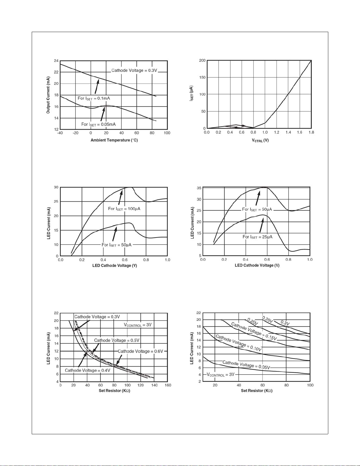
Typical Performance Characteristics
FAN5611/FAN5612/FAN5613/FAN5614
Figure 3. FAN5611/12/13
Output Current vs. Temerature
Figure 5. FAN5611/12/13
LED Current vs. LED Cathode Voltage
Figure 4. I
SET
vs. V
CTRL
Figure 6. FAN5614
LED Current vs. LED Cathode Voltage
Figure 7. FAN5611/12/13
Figure 8. FAN5614 LED Current vs. Set Resistor
LED Current vs. Set Resistor
© 2003 Fairchild Semiconductor Corporation www.fairchildsemi.com
FAN5611/FAN5612/FAN5613/FAN5614 Rev. 1.0.9 6
Page 7
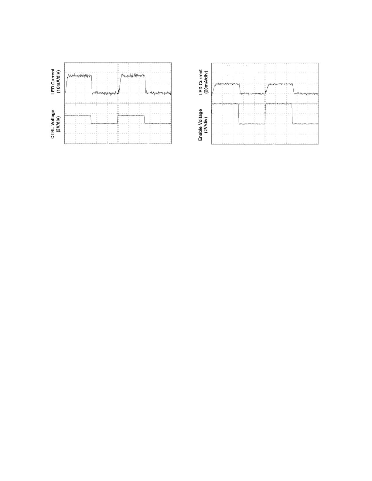
Typical Performance Characteristics (Continued)
FAN5611/FAN5612/FAN5613/FAN5614
Figure 9. FAN5611/12/13/14
Control Voltage Transient Response
Figure 10. FAN5612/13/14
Enable Voltage Transient Response
© 2003 Fairchild Semiconductor Corporation www.fairchildsemi.com
FAN5611/FAN5612/FAN5613/FAN5614 Rev. 1.0.9 7
Page 8
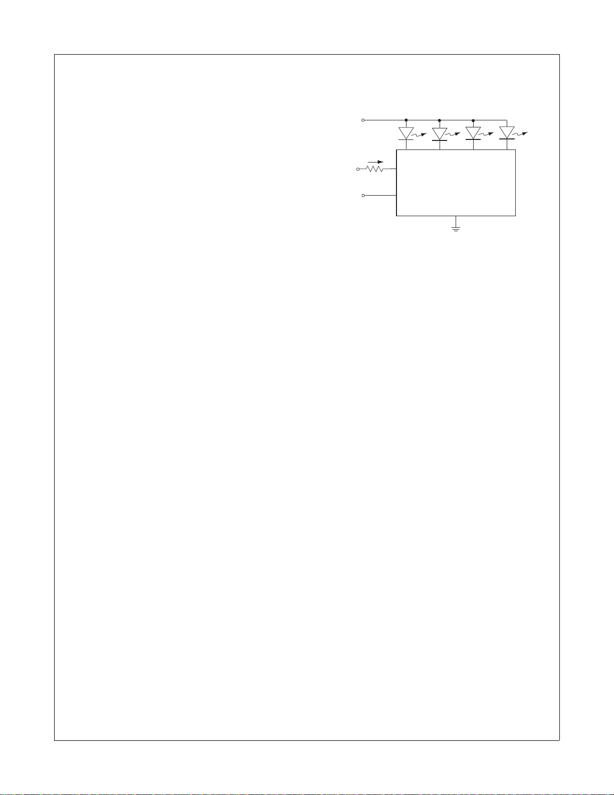
Application Information
Operational Descripton
The regulated current through each LED is a multiplication of the I
the R
SET
I
= I
SET
LED
Reference Figure 4, the I
mate V
CTRL
to the formula:
R
= (V
SET
For example, with V
through the LED results in I
to an approximate value of 1.2V for V
ure 4. The resulting R
ulation is 36kΩ.
The LED intensity can be adjusted by varying the duty
cycle of a square wave applied to the enable pin. Fr equency greater than 100Hz is best to avoid a "flickering"
effect. The maximum operation frequency is 10MHz.
Efficiency Considerations
The FAN561X driver’s low-dropout architecture can significantly improve the efficiency compared to using simple ballast resistors. The system efficiency, defined as
the ratio between the LEDs’ power and the input supplied power, can be calculated as:
Efficiency V
The lower the V
ciency. Efficiency can be further improved by using a
higher V
Application Notes
The ultra-low voltage drop across the FAN561X series of
LED drivers allows the devices to drive white, blue, and
other color LEDs in a wide range of input voltages. The
driver can be used in many applications. Although only
the FAN5613 is shown in all three examples, any of the
FAN561X-series LED drivers can be used in the applications presented, due to their similar operation.
Example 1: Drive low V
from single cell Li-ion
When using white or blue low VF LEDs, and utilizing the
drivers low voltage drop, only 3.4V in V
the full 20mA LED current. At 3.1V, there is 5mA typical
current available for the LEDs. The single cell Li-ion is
utilized in applications like cell phones or digital still cameras. In most cases, the Li-ion battery voltage level only
goes down to 3.0V voltage level, not down to the full discharge level (2.7V) before requesting the charger.
current. The I
SET
value. The I
SET
value is determined by
SET
value can be calculated as:
/ Current Gain
vs. V
. The value of R
CONTROL
INVCATHODE
CATHODE
with more LEDs, as shown in Example 3.
IN
SET
is calculated according
SET
- V
) / I
CTRL
CONTROL
SET
SET
= 3V, a 10mA current limit
= 50µA. That translates
SET
value that maintains 10mA reg-
–()VIN⁄=
, the higher the system effi-
white or blue LEDs directly
F
graph, to esti-
CTRL
, shown in Fig-
CTRL
is needed for
IN
V
IN
I
V
CONTROL
ENABLE
–V
DROP
–V
F (at 20mA)
–V
IN (at 20mA) =VDROP
–V
IN (at 5mA Typical)
where V
= Single cell Li-ion voltage.
IN
SET
CTRL
R
SET
ON/OFF
< 0.3V
< 3.1V (Low VF)
I4
~ 3.1V
I3
FAN5613
GND
+ VF = 3.4V
I2
I1
Key advantages:
• No boost circuit is needed for the LCD or keyboard
backlight.
• Drivers are directly connected to a Li-ion battery.
• No EMI, no switching noise, no boost efficiency lost,
no capacitor, and no inductor.
Example 2: Drive high VF white or blue LEDs from
existing bus from 4.0V to 5.5V
High VF white or blue LEDs have forward voltage drop in
the range of 3.2V to 4.0V. Driving these LEDs with the
maximum current of 20mA for maximum brightness,
usually requires a boost circuit for a single cell Li-ion
voltage range. In some cases, there is already a voltage
bus in the system, which can be utilized. Due to the ultralow voltage drop of the FAN561X series of LED drivers to
drive high-V
only 300mV higher than the highest V
–V
–V
–V
–V
where V
white or blue LEDs, the VIN needs to be
F
< 0.3V
DROP
F (at 20mA)
IN (at 20mA) =VDROP
IN (at 5mA Typical)
IN
< 3.3V to 4.0V (High VF)
+ VF = 3.6V to 4.3V
~ 3.3V
= existing bus = 3.3V to 4.3V.
in the circuit.
F
Key advantages:
• No boost circuit is needed for LCD or keyboard
backlight.
• Driver utilizes the existing bus.
• Ultra-low voltage drop provides the full 20mA LED
current at the lowest possible voltage level.
FAN5611/FAN5612/FAN5613/FAN5614
© 2003 Fairchild Semiconductor Corporation www.fairchildsemi.com
FAN5611/FAN5612/FAN5613/FAN5614 Rev. 1.0.9 8
Page 9
FAN5611/FAN5612/FAN5613/FAN5614
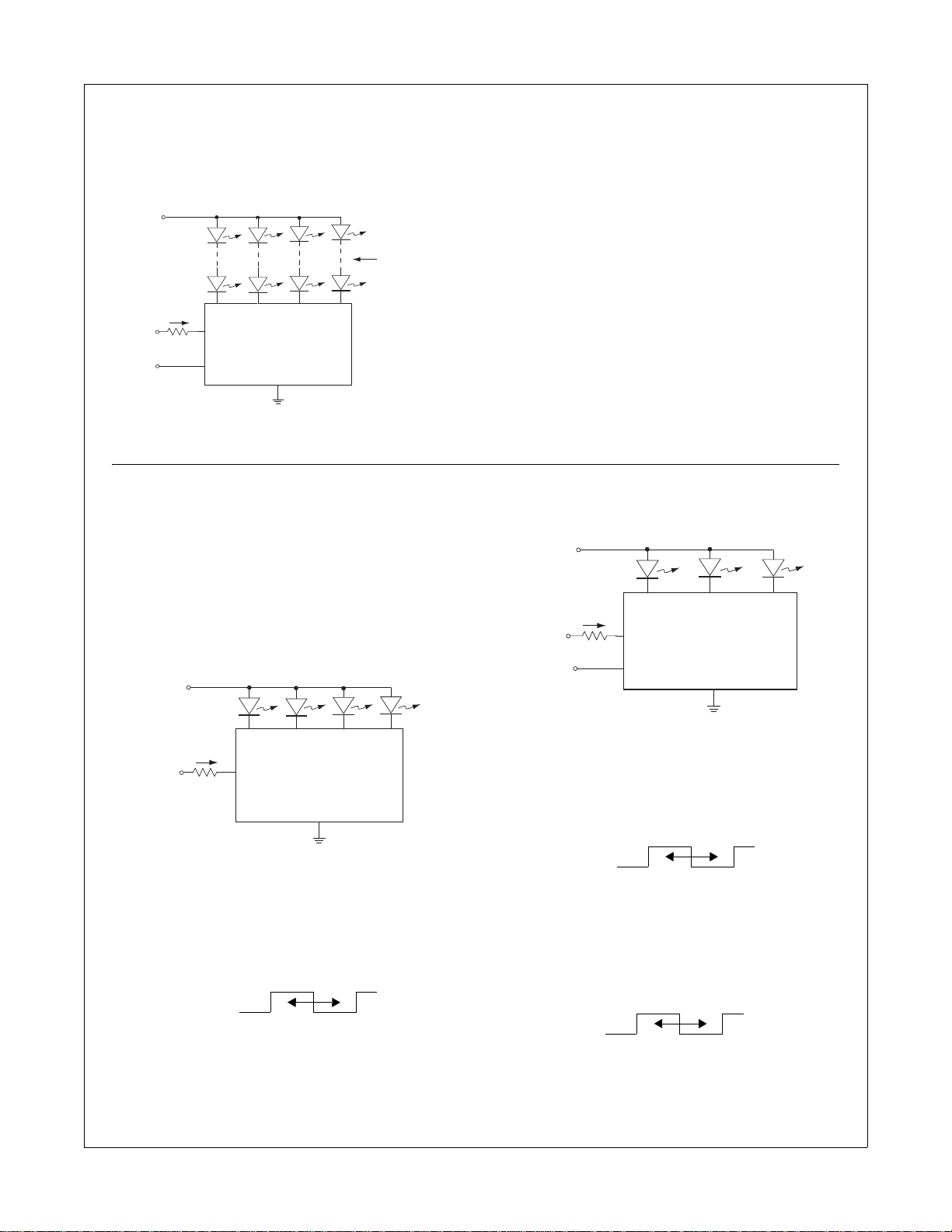
Example 3: Drive white, blue, red, amber LEDs string
Assuming a boost circuit or existing voltage bus, the
FAN561X series of LED drivers can be used to drive a
whole string of LEDs with flexible brightness control via
analog and/or PWM. .
V
IN
'N' number of
LEDs Per Branch
I
V
CONTROL
ENABLE
SET
CTRL
R
SET
FAN5613
ON/OFF
GND
I1I2I3I4
LED Brightness Control
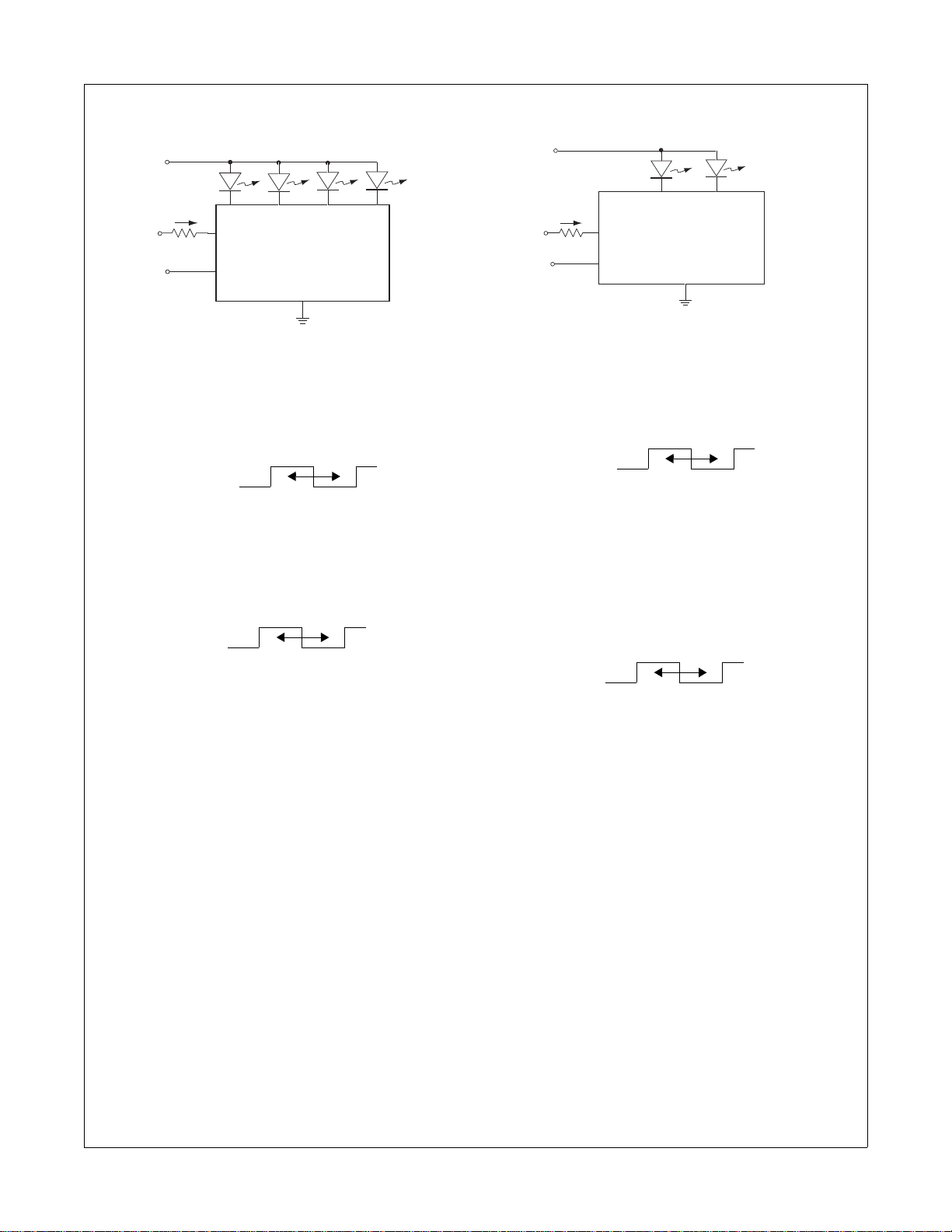
All of the FAN561X LED drivers feature analog and
PWM controls to give designers flexible brightness control. These control methods can be applied to the circuit
in two different ways to provide more flexibility than other
solutions. To determine the value of R
vs. V
graph in Figure 4.
CTRL
1. FAN5611
V
IN
, use the I
SET
SET
–V
–V
–V
< 0.3V
DROP
IN_MIN
IN _MAX
= N ¥ VF + V
DROP
= N ¥ VF + 5.5V
where VIN = existing bus, boost voltage.
Key advantage:
• No need for current matching resistors and discrete
transistor for brightness control.
2. FAN5612
V
IN
V
CONTROL
ENABLE
I
SET
R
SET
ON/OFF
I3
CTRL
I2
FAN5612
GND
I1
I
SET
(3V
V
CONTROL
)
R
SET
CTRL
FAN5611
GND
- Analog
Set V
I
LED
CONTROL
and R
200 V
-------------------------------------------------------------------------=
for LED current using:
SET
R
–()×
SET
CONTROLVCTRL
- PWM
V
CONTROL
= PWM
– Amplitude sets maximum LED current.
– Pulse width controls between 0 and maximum.
I1I2I3I4
- Analog
Set V
CONTROL
and R
for LED current using:
SET
- PWM - 1
I
LED
V
CONTROL
200 V
-------------------------------------------------------------------------=
= PWM
CONTROLVCTRL
R
–()×
SET
– Amplitude sets maximum LED current.
– Pulse width controls between 0 and maximum.
- PWM - 2
Set V
I
LED
CONTROL
200 I
×∼
and R
SET
for maximum LED current using:
SET
ON/OFF = PWM
– Amplitude has no effect on current.
– Pulse width controls between 0 and maximum.
© 2003 Fairchild Semiconductor Corporation www.fairchildsemi.com
FAN5611/FAN5612/FAN5613/FAN5614 Rev. 1.0.9 9
Page 10
FAN5611/FAN5612/FAN5613/FAN5614
3. FAN5613
V
IN
I
V
CONTROL
ENABLE
R
SET
I4
CTRL
SET
ON/OFF
- Analog
Set V
I
LED
CONTROL
and R
200 V
-------------------------------------------------------------------------=
CONTROLVCTRL
- PWM - 1
V
CONTROL
= PWM
– Amplitude sets maximum LED current.
– Pulse width controls between 0 and maximum.
- PWM - 2
Set V
I
LED
CONTROL
200 I
×∼
and R
SET
ON/OFF = PWM
– Amplitude has no effect on current.
– Pulse width controls between 0 and maximum.
I3
I2
I1
FAN5613
V
SS
for LED current using:
SET
–()×
R
SET
for maximum LED current using:
SET
4. FAN5614
V
IN
I
V
CONTROL
ENABLE
SET
R
SET
ON/OFF
CTRL
FAN5614
- Analog
Set V
I
LED
CONTROL
and R
200 V
-------------------------------------------------------------------------=
for LED current using:
SET
R
–()×
SET
CONTROLVCTRL
- PWM - 1
V
CONTROL
= PWM
– Amplitude sets maximum LED current.
– Pulse width controls between 0 and maximum.
- PWM - 2
Set V
I
LED
I
LED
CONTROL
200 I
×∼
200 V
-------------------------------------------------------------------------=
and R
SET
for maximum LED current using:
SET
R
–()×
SET
CONTROLVCTRL
ON/OFF = PWM
– Amplitude has no effect on current.
– Pulse width controls between 0 and maximum.
I3/I4I1/I2
V
SS
© 2003 Fairchild Semiconductor Corporation www.fairchildsemi.com
FAN5611/FAN5612/FAN5613/FAN5614 Rev. 1.0.9 10
Page 11
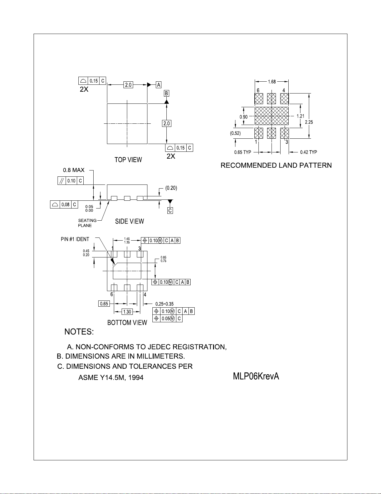
Mechanical Dimensions
2x2mm 6-Lead MLP
FAN5611/FAN5612/FAN5613/FAN5614
© 2003 Fairchild Semiconductor Corporation www.fairchildsemi.com
FAN5611/FAN5612/FAN5613/FAN5614 Rev. 1.0.9 11
Page 12
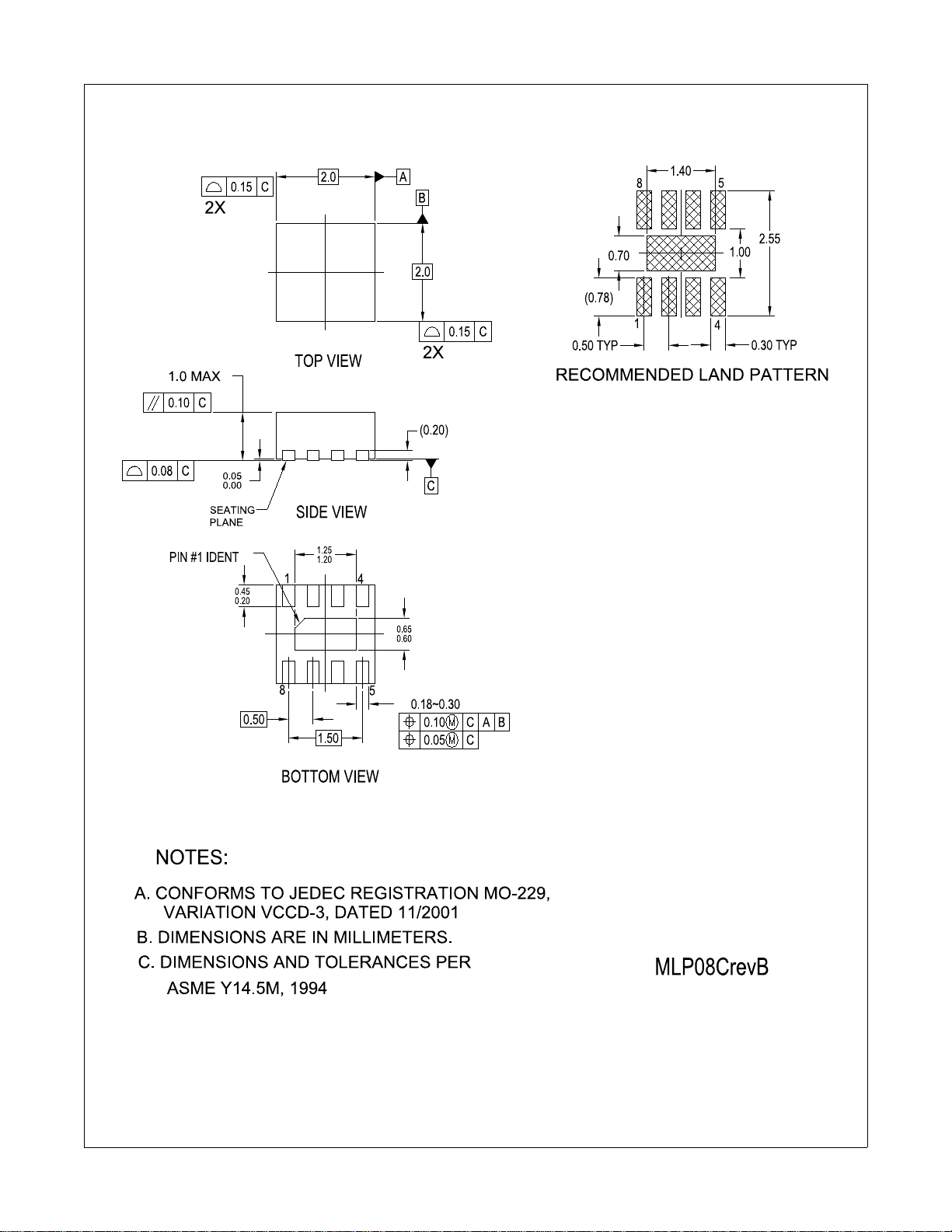
Mechanical Dimensions
2x2mm 8-Lead MLP
FAN5611/FAN5612/FAN5613/FAN5614
© 2003 Fairchild Semiconductor Corporation www.fairchildsemi.com
FAN5611/FAN5612/FAN5613/FAN5614 Rev. 1.0.9 12
Page 13
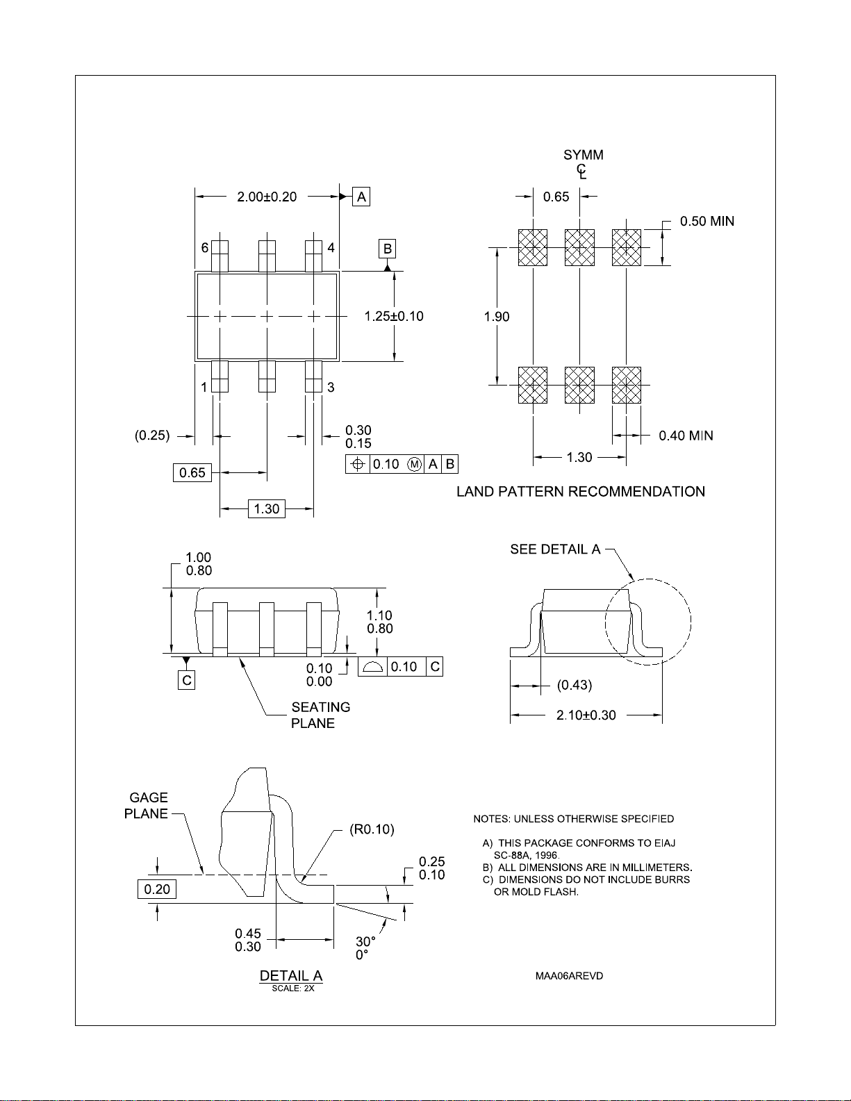
Mechanical Dimensions
6-Lead SC-70 Package
FAN5611/FAN5612/FAN5613/FAN5614
© 2003 Fairchild Semiconductor Corporation www.fairchildsemi.com
FAN5611/FAN5612/FAN5613/FAN5614 Rev. 1.0.9 13
Page 14
FAN5611/FAN5612/FAN5613/FAN5614
© 2003 Fairchild Semiconductor Corporation www.fairchildsemi.com
FAN5611/FAN5612/FAN5613/FAN5614 Rev. 1.0.9 14
 Loading...