

Page 1
FAN3213 / FAN3214
Dual-4A, High-Speed, Low-Side Gate Drivers
Features
Industry-Standard Pinouts
4.5 to 18V Operating Range
5A Peak Sink/Source at V
4.3A Sink / 2.8A Source at V
DD
= 12V
= 6V
OUT
TTL Input Thresholds
Two Versions of Dual Independent Drivers:
- Dual Inverting (FAN3213)
- Dual Non-Inverting (FAN3214)
Internal Resistors Turn Driver Off If No Inputs
MillerDrive™ Technology
12ns / 9ns Typical Rise/Fall Times with 2.2nF Load
Typical Propagation Delay Under 20ns Matched
within 1ns to the Other Channel
Double Current Capability by Paralleling Channels
Standard SOIC-8 Package
Rated from –40°C to +125°C Ambient
Applications
Switch-Mode Power Supplies
High-Efficiency MOSFET Switching
Synchronous Rectifier Circuits
DC-to-DC Converters
Motor Control
Description
The FAN3213 and FAN3214 dual 4A gate drivers are
designed to drive N-channel enhancement-mode
MOSFETs in low-side switching applications by
providing high peak current pulses during the short
switching intervals. They are both available with TTL
input thresholds. Internal circuitry provides an undervoltage lockout function by holding the output LOW until
the supply voltage is within the operating range. In
addition, the drivers feature matched internal
propagation delays between A and B channels for
applications requiring dual gate drives with critical
timing, such as synchronous rectifiers. This also
enables connecting two drivers in parallel to effectively
double the current capability driving a single MOSFET.
The FAN3213/14 drivers incorporate MillerDrive™
architecture for the final output stage. This bipolarMOSFET combination provides high current during the
Miller plateau stage of the MOSFET turn-on / turn-off
process to minimize switching loss, while providing railto-rail voltage swing and reverse current capability.
The FAN3213 offers two inverting drivers and the
FAN3214 offers two non-inverting drivers. Both are
offered in a standard 8-pin SOIC package.
FAN3213 / FAN3214 — Dual-4A, High-Speed, Low-Side Gate Drivers
July 2012
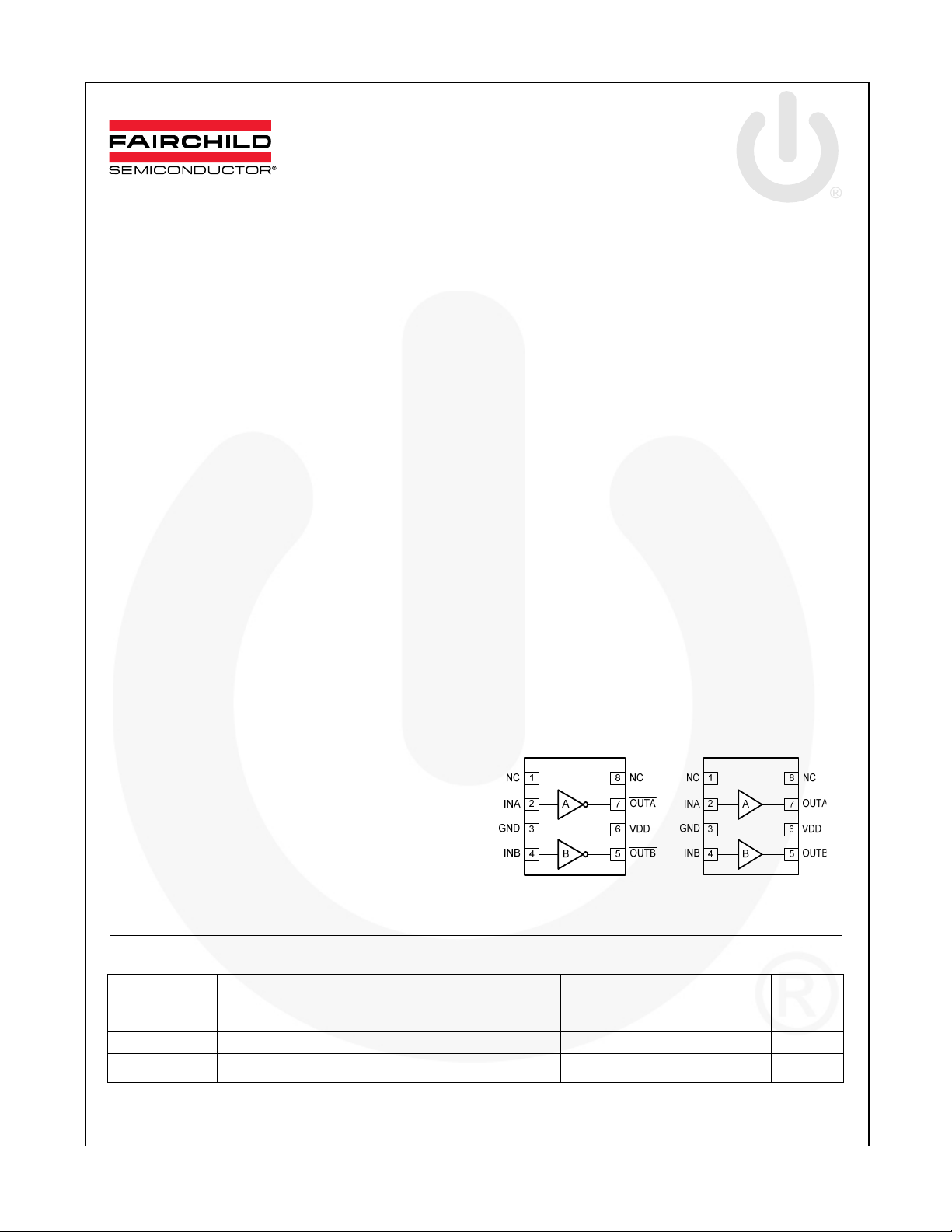
FAN3213 FAN3214
Figure 1. Pin Configurations
Ordering Information
Part Number Logic
FAN3213TMX Dual Inverting Channels TTL SOIC-8 Tape & Reel 2,500
FAN3214TMX Dual Non-Inverting Channels TTL SOIC-8 Tape & Reel 2,500
Input
Threshold
Package
Packing
Method
Quantity
per Reel
© 2008 Fairchild Semiconductor Corporation www.fairchildsemi.com
FAN3213 / FAN3214 • Rev. 1.0.4
Page 2
Package Outlines
FAN3213 / FAN3214 — Dual-4A, High-Speed, Low-Side Gate Drivers
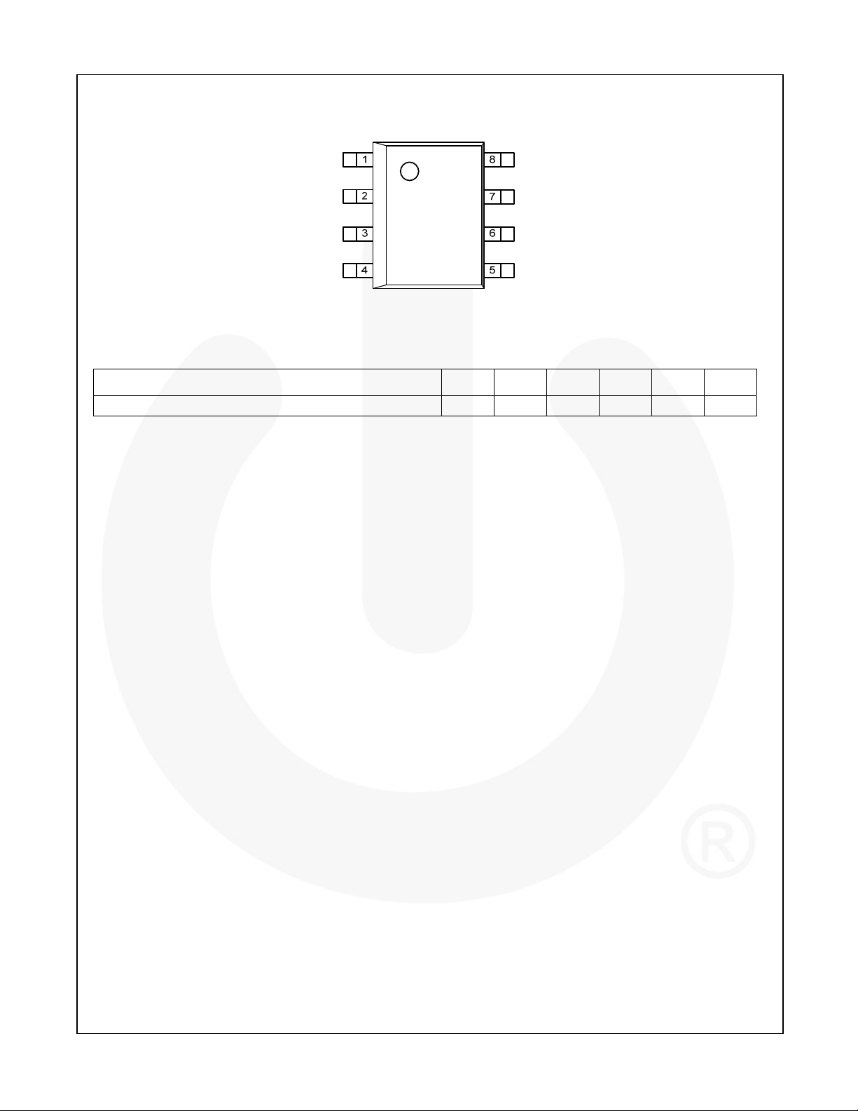
Figure 2. SOIC-8 (Top View)
Thermal Characteristics
Package
8-Pin Small Outline Integrated Circuit (SOIC)
Notes:
1. Estimates derived from thermal simulation; actual values depend on the application.
2. Theta_JL (
thermal pad) that are typically soldered to a PCB.
3. Theta_JT (
held at a uniform temperature by a top-side heatsink.
4. Theta_JA (Θ
The value given is for natural convection with no heatsink, using a 2S2P board, as specified in JEDEC standards JESD51-2,
JESD51-5, and JESD51-7, as appropriate.
5. Psi_JB (
application circuit board reference point for the thermal environment defined in Note 4. For the SOIC-8 package, the board
reference is defined as the PCB copper adjacent to pin 6.
6. Psi_JT (
the center of the top of the package for the thermal environment defined in Note 4.
): Thermal resistance between the semiconductor junction and the bottom surface of all the leads (including any
JL
): Thermal resistance between the semiconductor junction and the top surface of the package, assuming it is
JT
): Thermal resistance between junction and ambient, dependent on the PCB design, heat sinking, and airflow.
JA
): Thermal characterization parameter providing correlation between semiconductor junction temperature and an
JB
): Thermal characterization parameter providing correlation between the semiconductor junction temperature and
JT
(1)
(2)
JL
38 29 87 41 2.3 °C/W
(3)
JT
JA
(4)
JB
(5)
(6)
JT
Units
© 2008 Fairchild Semiconductor Corporation www.fairchildsemi.com
FAN3213 / FAN3214 • Rev. 1.0.4 2
Page 3
B
A
x
Pin Configurations
FAN3213 / FAN3214 — Dual-4A, High-Speed, Low-Side Gate Drivers
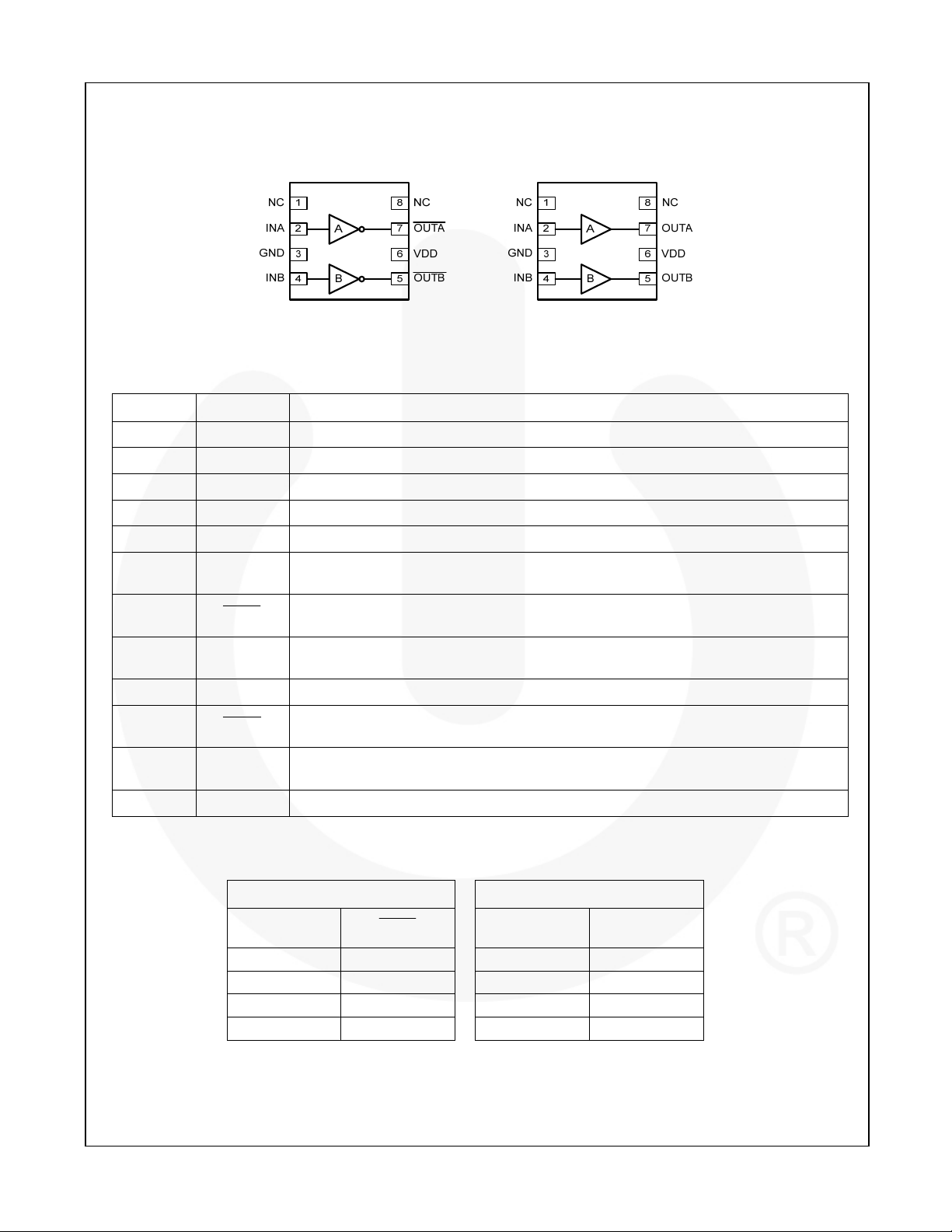
FAN3213 FAN3214
Figure 3. Pin Configurations (Repeated)
Pin Definitions
Pin Name Pin Description
1 NC
2 INA
3 GND
2 INA
4 INB
7
5
(FAN3213)
5
(FAN3214)
OUTA
OUT
OUTB
6 VDD
7
(FAN3213)
7
(FAN3214)
OUT
OUTA
8 NC
No Connect. This pin can be grounded or left floating.
Input to Channel A.
Ground. Common ground reference for input and output circuits.
Input to Channel A.
Input to Channel B.
Gate Drive Output A: Held LOW unless required input(s) are present and V
UVLO threshold.
Gate Drive Output B (inverted from the input): Held LOW unless required input is
present and V
is above UVLO threshold.
DD
Gate Drive Output B: Held LOW unless required input(s) are present and V
UVLO threshold.
Supply Voltage. Provides power to the IC.
Gate Drive Output A (inverted from the input): Held LOW unless required input is
present and V
is above UVLO threshold.
DD
Gate Drive Output A: Held LOW unless required input(s) are present and V
UVLO threshold.
No Connect. This pin can be grounded or left floating.
is above
DD
is above
DD
is above
DD
Output Logic
FAN3213 (x=A or B) FAN3214 (x=A or B)
INx
OUT
0 0 0
(7)
1
0 1 0
0 1 0
(7)
1
0 1 1
Note:
7. Default input signal if no external connection is made.
INx OUTx
(7)
0
(7)
0
© 2008 Fairchild Semiconductor Corporation www.fairchildsemi.com
FAN3213 / FAN3214 • Rev. 1.0.4 3
Page 4
Block Diagrams
FAN3213 / FAN3214 — Dual-4A, High-Speed, Low-Side Gate Drivers
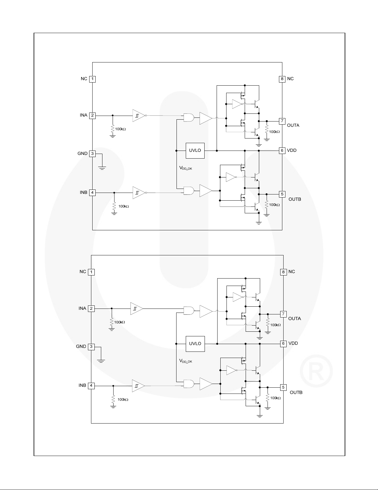
Figure 4. FAN3213 Block Diagram
Figure 5. FAN3214 Block Diagram
© 2008 Fairchild Semiconductor Corporation www.fairchildsemi.com
FAN3213 / FAN3214 • Rev. 1.0.4 4
Page 5
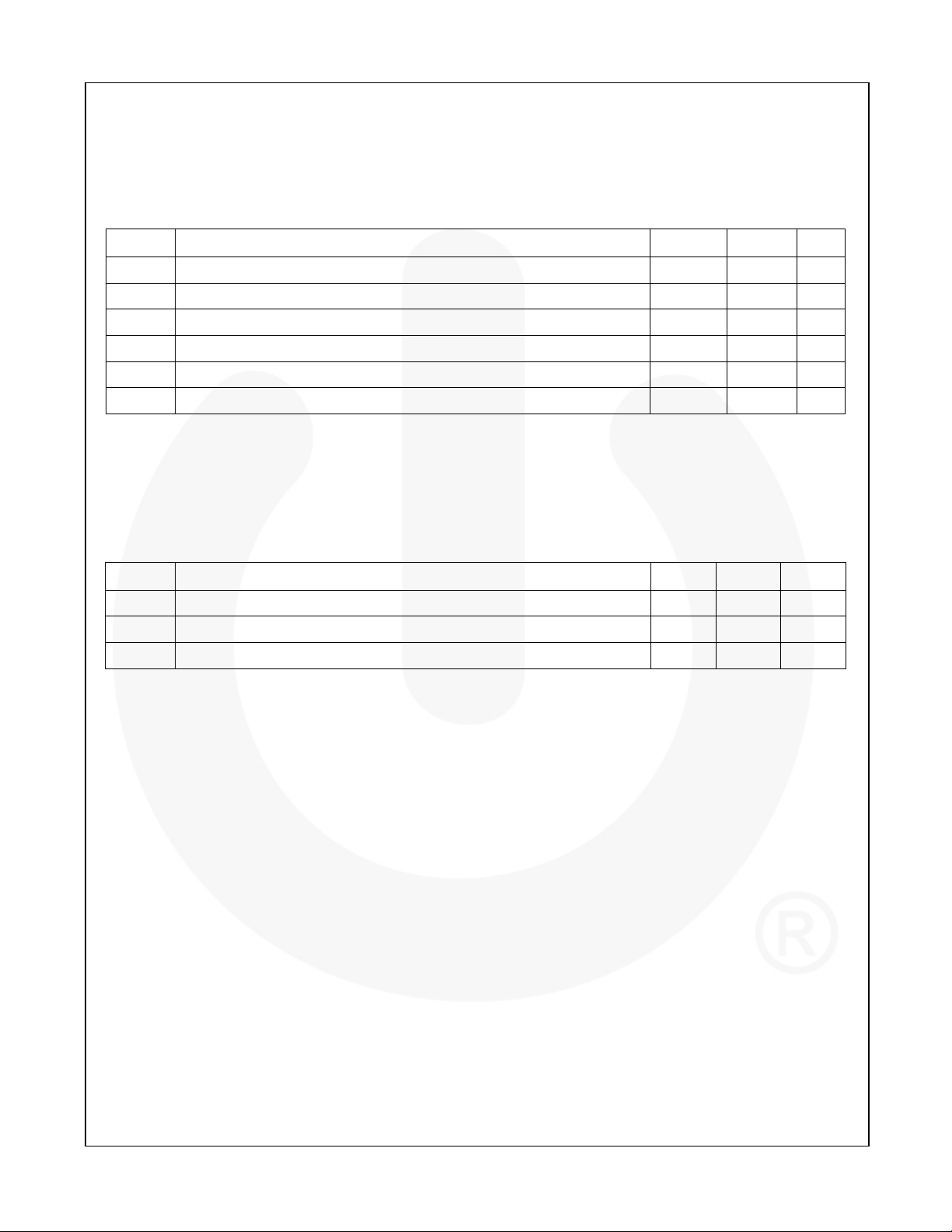
Absolute Maximum Ratings
Stresses exceeding the absolute maximum ratings may damage the device. The device may not function or be
operable above the recommended operating conditions and stressing the parts to these levels is not recommended.
In addition, extended exposure to stresses above the recommended operating conditions may affect device reliability.
The absolute maximum ratings are stress ratings only.
Symbol Parameter Min. Max. Unit
VDD VDD to PGND -0.3 20.0 V
VIN INA, INA+, INA–, INB, INB+ and INB– to GND GND - 0.3 VDD + 0.3 V
V
OUTA and OUTB to GND GND - 0.3 VDD + 0.3 V
OUT
TL Lead Soldering Temperature (10 Seconds) +260 ºC
TJ Junction Temperature -55 +150 ºC
T
Storage Temperature -65 +150 ºC
STG
Recommended Operating Conditions
The Recommended Operating Conditions table defines the conditions for actual device operation. Recommended
operating conditions are specified to ensure optimal performance to the datasheet specifications. Fairchild does not
recommend exceeding them or designing to Absolute Maximum Ratings.
FAN3213 / FAN3214 — Dual-4A, High-Speed, Low-Side Gate Drivers
Symbol Parameter Min. Max. Unit
VDD Supply Voltage Range 4.5 18.0 V
VIN Input Voltage INA, INA+, INA–, INB, INB+ and INB– 0 VDD V
TA Operating Ambient Temperature -40 +125 ºC
© 2008 Fairchild Semiconductor Corporation www.fairchildsemi.com
FAN3213 / FAN3214 • Rev. 1.0.4 5
Page 6
FAN3213 / FAN3214 — Dual-4A, High-Speed, Low-Side Gate Drivers
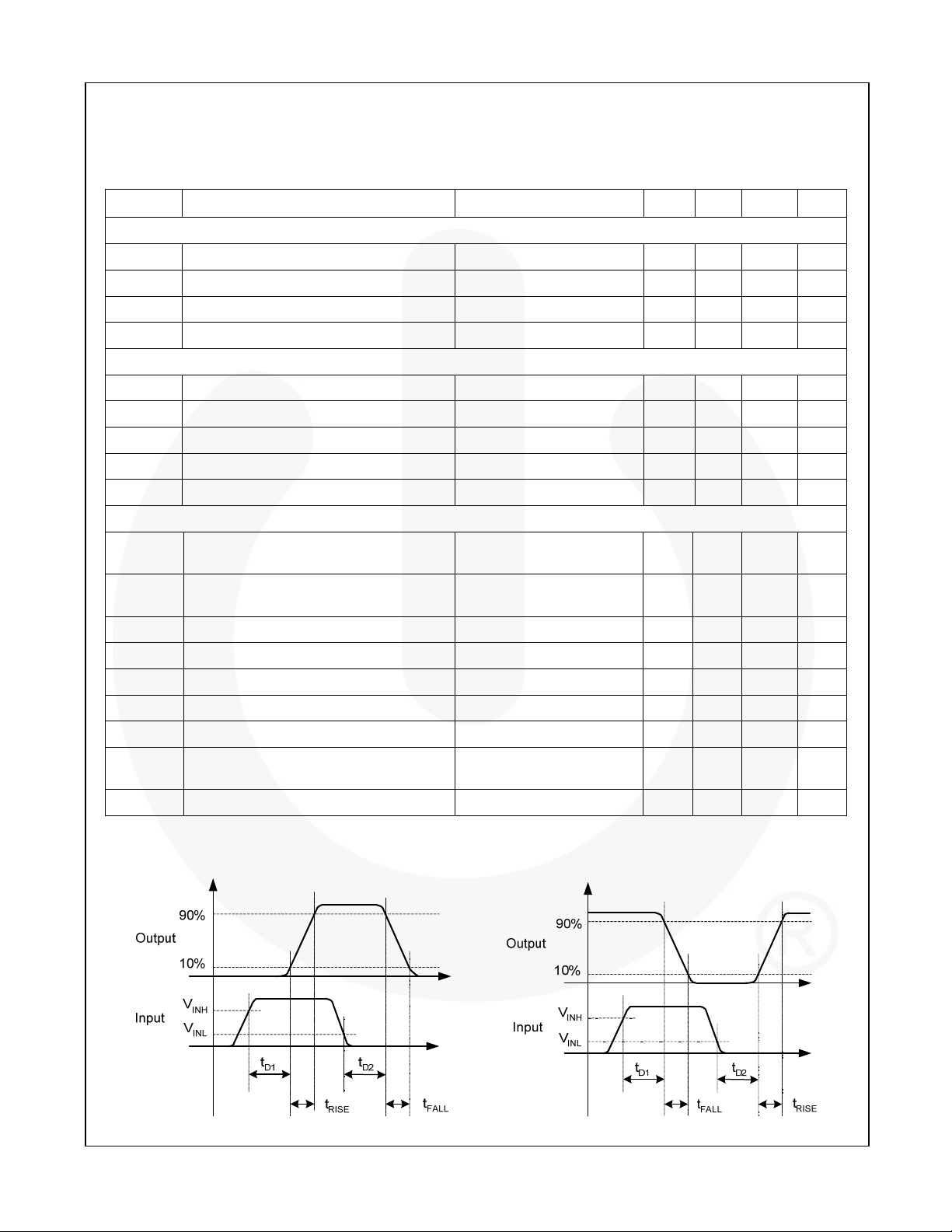
Electrical Characteristics
Unless otherwise noted, VDD=12V, TJ=-40°C to +125°C. Currents are defined as positive into the device and negative
out of the device.
Symbol Parameter Conditions Min. Typ. Max. Unit
Supply
VDD Operating Range 4.5 18.0 V
IDD Supply Current, Inputs Not Connected 0.70 0.95 mA
VON Turn-On Voltage INA = VDD, INB = 0V 3.5 3.9 4.3 V
V
Turn-Off Voltage INA = VDD, INB = 0V 3.3 3.7 4.1 V
OFF
Inputs
V
INx Logic Low Threshold 0.8 1.2 V
IL_T
V
INx Logic High Threshold 1.6 2.0 V
IH_T
I
Non-Inverting Input IN from 0 to VDD -1.5 175.0 µA
IN+
I
Inverting Input IN from 0 to VDD -175.0 1.5 µA
IN-
V
TTL Logic Hysteresis Voltage 0.2 0.4 0.8 V
HYS_T
Output
I
OUT Current, Mid-Voltage, Sinking
SINK
I
OUT Current, Mid-Voltage, Sourcing
SOURCE
I
OUT Current, Peak, Sinking
PK_SINK
I
PK_SOURCE
OUT Current, Peak, Sourcing
t
Output Rise Time
RISE
t
Output Fall Time
FALL
(9)
(9)
C
C
(8)
(8)
C
(8)
C
tD1, tD2 Output Propagation Delay, TTL Inputs
Propagation Matching Between Channels
I
Output Reverse Current Withstand
RVS
(8)
Notes:
8. Not tested in production.
9. See Timing Diagrams of Figu re 6 and Figure 7.
OUTx at VDD/2,
C
=0.22µF, f=1kHz
LOAD
OUTx at V
(8)
C
LOAD
LOAD
LOAD
LOAD
LOAD
(9)
0 - 5VIN, 1V/ns Slew Rate 9 17 29 ns
/2,
DD
=0.22µF, f=1kHz
=0.22µF, f=1kHz 5 A
=0.22µF, f=1kHz -5 A
=2200pF 12 20 ns
=2200pF 9 17 ns
INA=INB, OUTA and OUTB
at 50% Point
4.3 A
-2.8 A
2 4 ns
500 mA
Figure 6. Non-Inverting Timing Diagram Figure 7. Inverting Timing Diagram
© 2008 Fairchild Semiconductor Corporation www.fairchildsemi.com
FAN3213 / FAN3214 • Rev. 1.0.4 6
Page 7
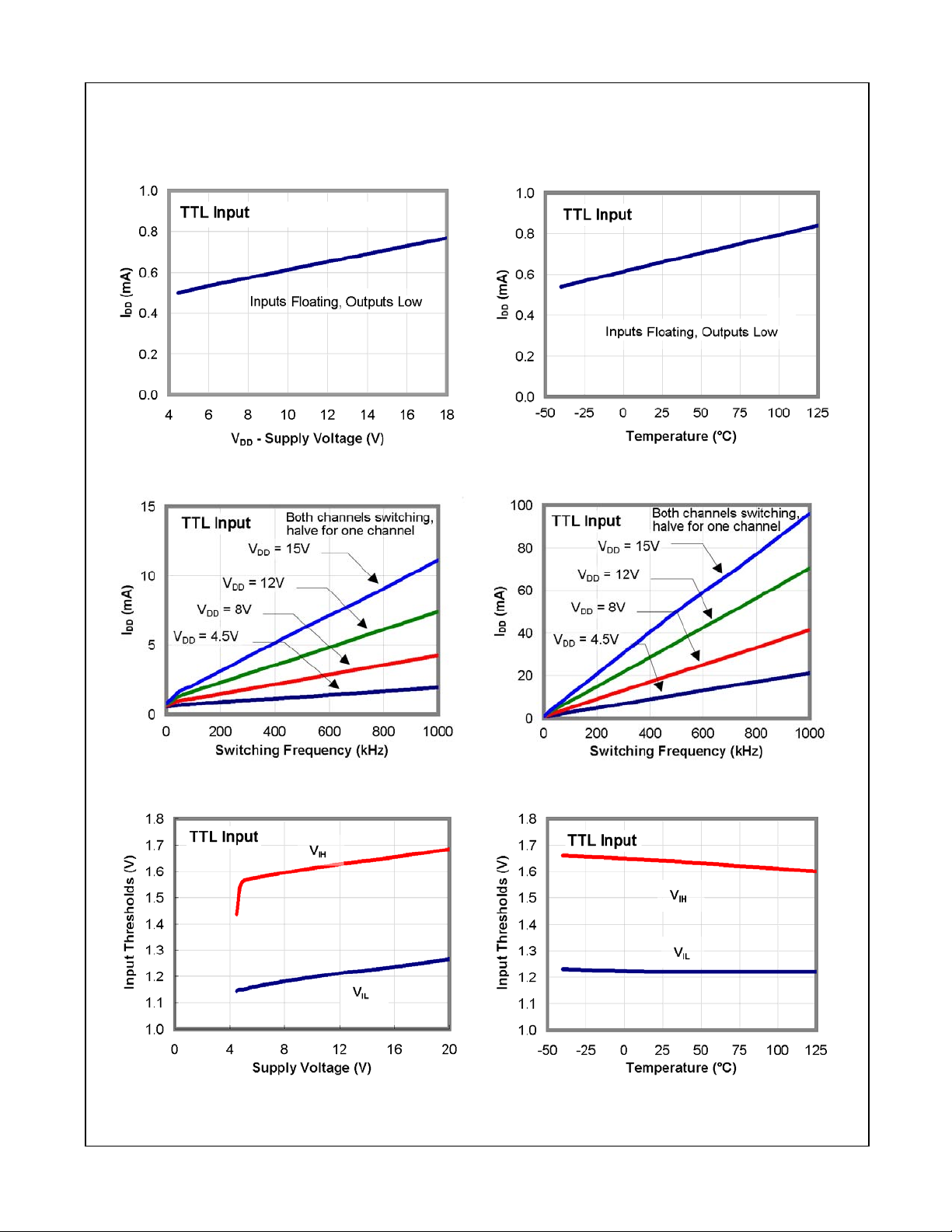
Typical Performance Characteristics
Typical characteristics are provided at TA=25°C and VDD=12V unless otherwise noted.
Figure 8. IDD (Static) vs. Supply Voltage
(10)
Figure 9. IDD (Static) vs. Temperature
(10)
FAN3213 / FAN3214 — Dual-4A, High-Speed, Low-Side Gate Drivers
Figure 10. IDD (No Load) vs. Frequency Figure 11. IDD (2.2nF Load) vs. Frequency
Figure 12. Input Thresholds vs. Supply Voltage Figure 13. Input Thresholds vs. Temperature
© 2008 Fairchild Semiconductor Corporation www.fairchildsemi.com
FAN3213 / FAN3214 • Rev. 1.0.4 7
Page 8
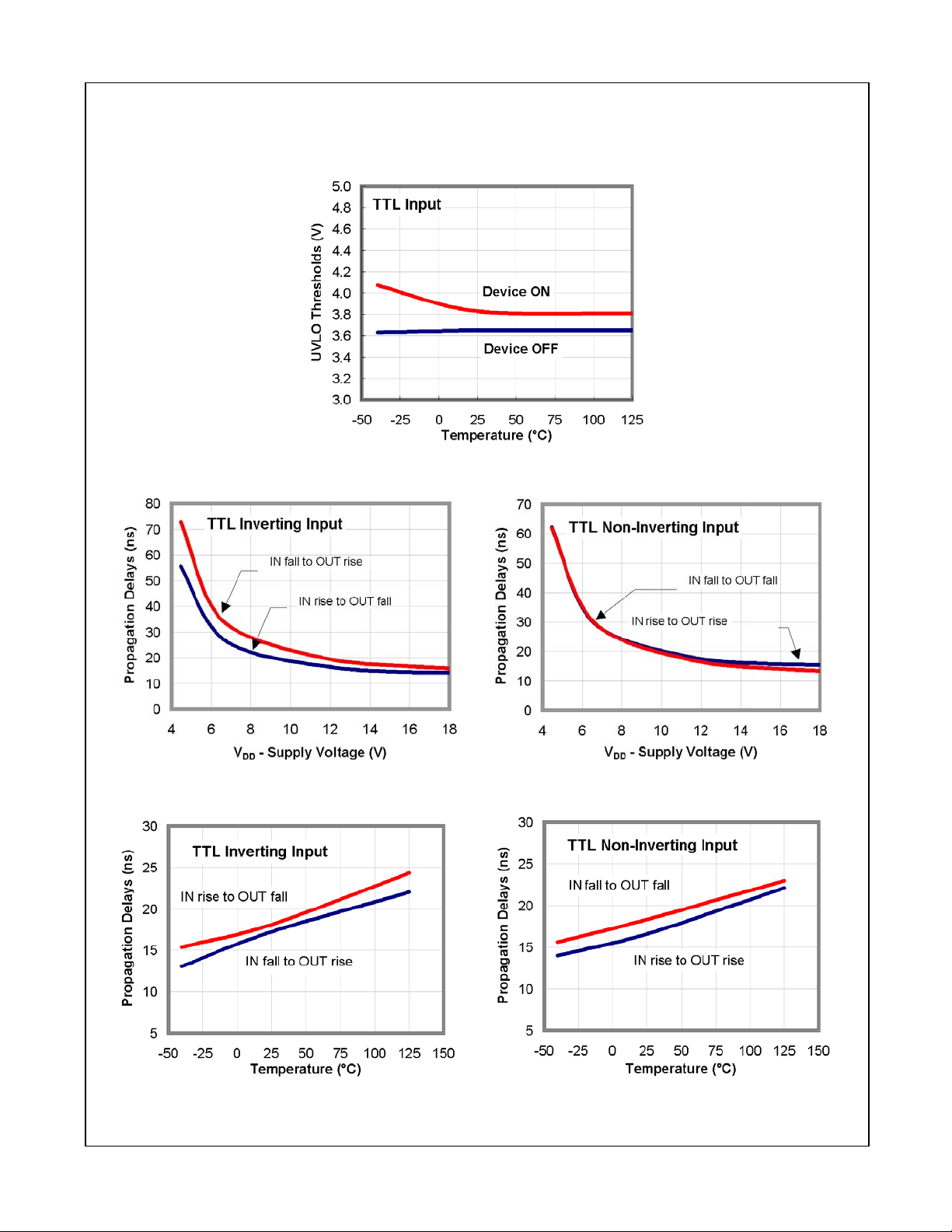
Typical Performance Characteristics
Typical characteristics are provided at TA=25°C and VDD=12V unless otherwise noted.
UVLO Threshold vs. Temperature
FAN3213 / FAN3214 — Dual-4A, High-Speed, Low-Side Gate Drivers
Figure 14. Propagation Delay vs. Supply Voltage Figure 15. Propagation Delay vs. Supply Voltage
Figure 16. Propagation Delays vs. Temperature Figure 17. Propagation Delays vs. Temperature
© 2008 Fairchild Semiconductor Corporation www.fairchildsemi.com
FAN3213 / FAN3214 • Rev. 1.0.4 8
Page 9
Typical Performance Characteristics
Typical characteristics are provided at TA=25°C and VDD=12V unless otherwise noted.
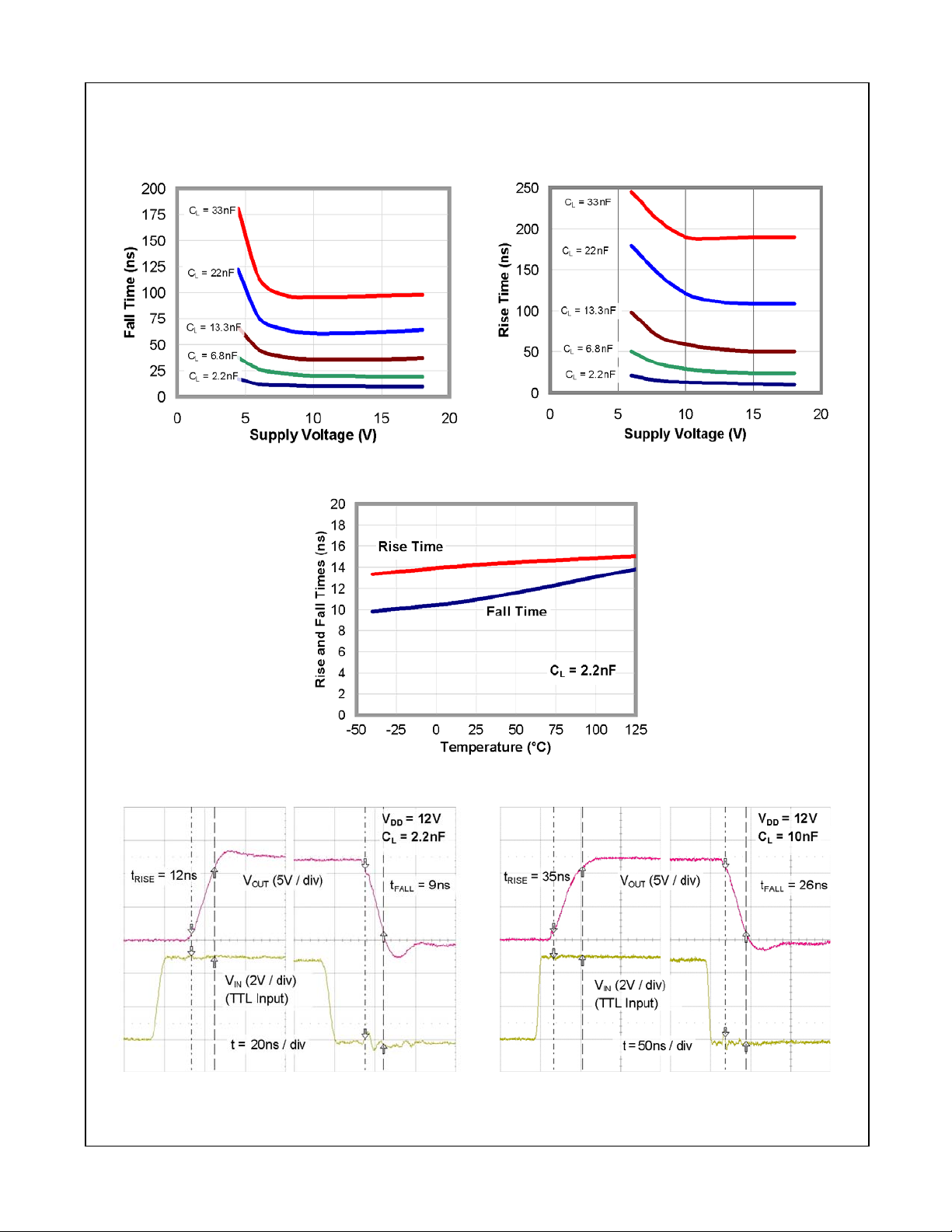
Figure 18. Fall Time vs. Supply Voltage Figure 19. Rise Time vs. Supply Voltage
FAN3213 / FAN3214 — Dual-4A, High-Speed, Low-Side Gate Drivers
Figure 20. Rise and Fall Times vs. Temperature
Figure 21. Rise/Fall Waveforms with 2.2nF Load Figure 22. Rise/Fall Waveforms with 10nF Load
© 2008 Fairchild Semiconductor Corporation www.fairchildsemi.com
FAN3213 / FAN3214 • Rev. 1.0.4 9
Page 10
Typical Performance Characteristics
Typical characteristics are provided at TA=25°C and VDD=12V unless otherwise noted.
FAN3213 / FAN3214 — Dual-4A, High-Speed, Low-Side Gate Drivers
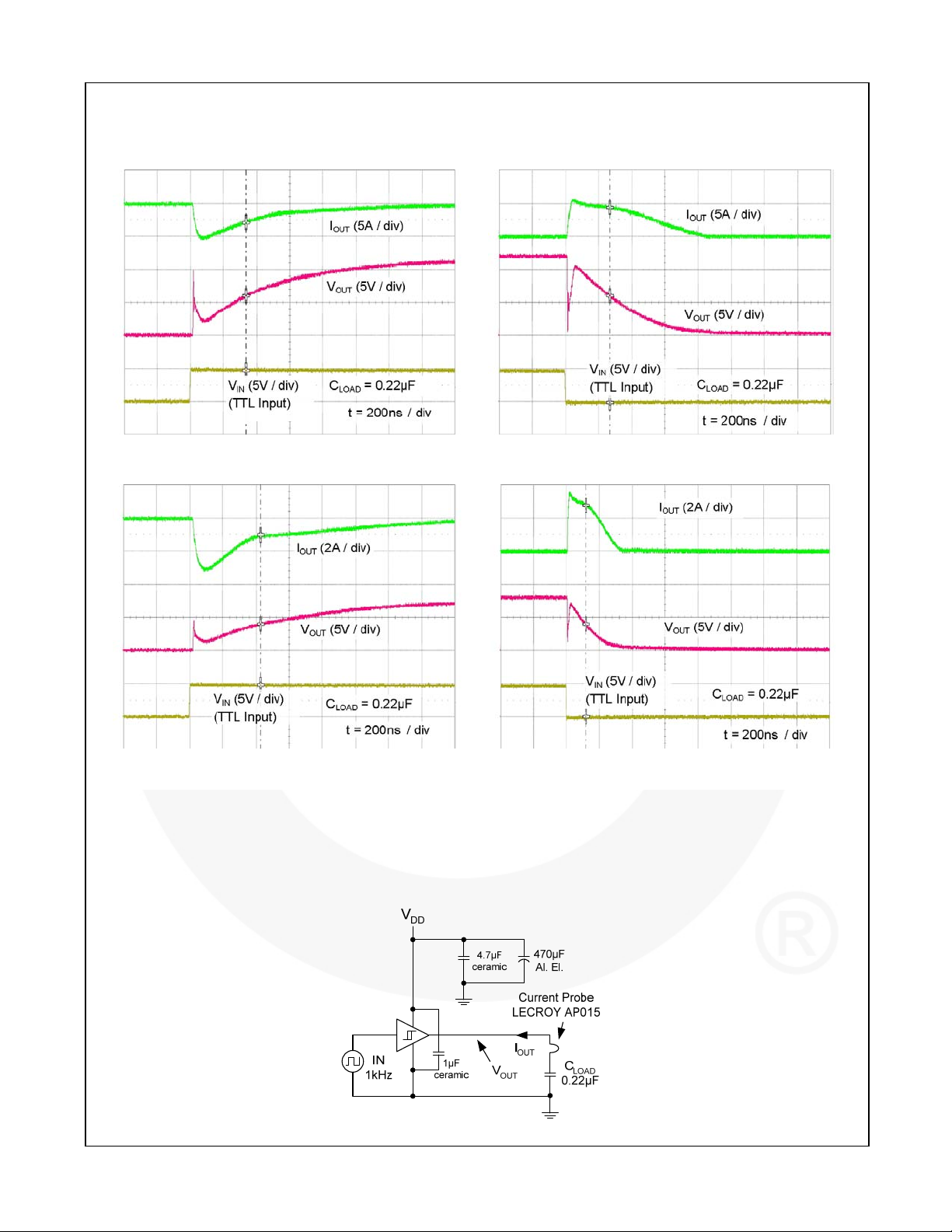
Figure 23. Quasi-Static Source Current
with VDD=12V
Figure 25. Quasi-Static Source Current
with VDD=8V
(11)
(11)
Figure 24. Quasi-Static Sink Current with VDD=12V
Figure 26. Quasi-Static Sink Current with VDD=8V
Notes:
10. For any inverting inputs pulled LOW, non-inverting inputs pulled HIGH, or outputs driven HIGH; static I
DD
increases by the current flowing through the corresponding pull-up/down resistor shown in Figure 4 and Figure 5.
11. The initial spike in each current waveform is a measurement artifact caused by the stray inductance of the
current-measurement loop.
(11)
(11)
Test Circuit
Figure 27. Quasi-Static I
© 2008 Fairchild Semiconductor Corporation www.fairchildsemi.com
FAN3213 / FAN3214 • Rev. 1.0.4 10
OUT
/ V
OUT
Test Circuit
Page 11
Applications Information
Input Thresholds
The FAN3213 and the FAN3214 drivers consist of two
identical channels that may be used independently at
rated current or connected in parallel to double the
individual current capacity.
The input thresholds meet industry-standard TTL-logic
thresholds independent of the V
a hysteresis voltage of approximately 0.4V. These levels
permit the inputs to be driven from a range of input logic
signal levels for which a voltage over 2V is considered
logic HIGH. The driving signal for the TTL inputs should
have fast rising and falling edges with a slew rate of
6V/µs or faster, so a rise time from 0 to 3.3V should be
550ns or less. With reduced slew rate, circuit noise
could cause the driver input voltage to exceed the
hysteresis voltage and retrigger the driver input, causing
erratic operation.
Static Supply Current
In the IDD (static) typical performance characteristics
shown in Figure 8 and Figure 9, each curve is produced
with both inputs floating and both outputs LOW to
indicate the lowest static I
additional current flows through the 100k resistors on
the inputs and outputs shown in the block diagram of
each part (see Figure 4 and Figure 5). In these cases,
the actual static I
current is the value obtained from
DD
the curves plus this additional current.
MillerDrive™ Gate Drive Technology
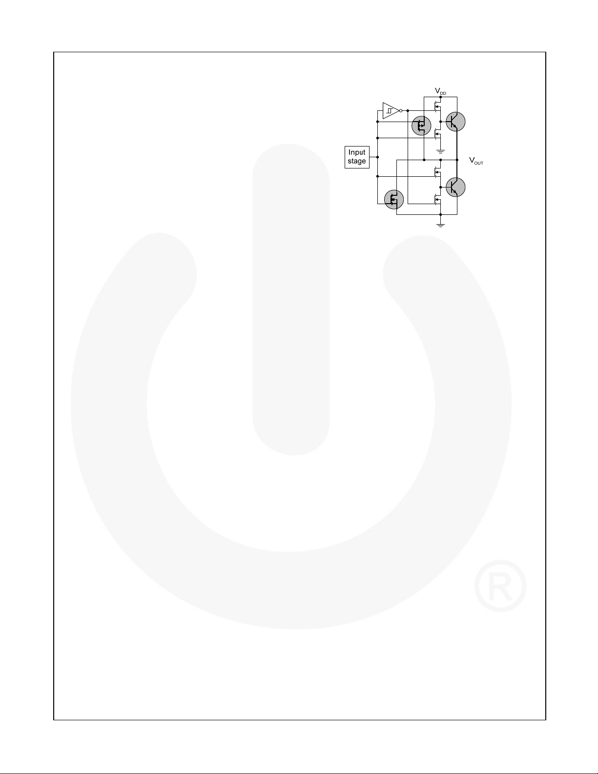
FAN3213 and FAN3214 gate drivers incorporate the
MillerDrive™ architecture shown in Figure 28. For the
output stage, a combination of bipolar and MOS devices
provide large currents over a wide range of supply
voltage and temperature variations. The bipolar devices
carry the bulk of the current as OUT swings between 1/3
to 2/3 VDD and the MOS devices pull the output to the
HIGH or LOW rail.
The purpose of the MillerDrive™ architecture is to
speed up switching by providing high current during the
Miller plateau region when the gate-drain capacitance of
the MOSFET is being charged or discharged as part of
the turn-on / turn-off process.
For applications with zero voltage switching during the
MOSFET turn-on or turn-off interval, the driver supplies
high peak current for fast switching even though the
Miller plateau is not present. This situation often occurs
in synchronous rectifier applications because the body
diode is generally conducting before the MOSFET is
switched ON.
The output pin slew rate is determined by VDD voltage
and the load on the output. It is not user adjustable, but
a series resistor can be added if a slower rise or fall time
at the MOSFET gate is needed.
voltage, and there is
DD
current. For other states,
DD
Figure 28. MillerDrive™ Output Architecture
Under-Voltage Lockout
The FAN321x startup logic is optimized to drive groundreferenced N-channel MOSFETs with an under-voltage
lockout (UVLO) function to ensure that the IC starts up
in an orderly fashion. When V
is rising, yet below the
DD
3.9V operational level, this circuit holds the output LOW,
regardless of the status of the input pins. After the part
is active, the supply voltage must drop 0.2V before the
part shuts down. This hysteresis helps prevent chatter
when low V
supply voltages have noise from the
DD
power switching. This configuration is not suitable for
driving high-side P-channel MOSFETs because the low
output voltage of the driver would turn the P-channel
MOSFET on with VDD below 3.9V.
VDD Bypass Capacitor Guidelines
To enable this IC to turn a device ON quickly, a local
high-frequency bypass capacitor, C
, with low ESR
BYP
and ESL should be connected between the VDD and
GND pins with minimal trace length. This capacitor is in
addition to bulk electrolytic capacitance of 10µF to 47µF
commonly found on driver and controller bias circuits.
A typical criterion for choosing the value of C
keep the ripple voltage on the V
supply to ≤ 5%. This
DD
BYP
is to
is often achieved with a value ≥ 20 times the equivalent
load capacitance C
, defined here as Q
EQV
GATE/VDD
Ceramic capacitors of 0.1µF to 1µF or larger are
common choices, as are dielectrics, such as X5R and
X7R, with good temperature characteristics and high
pulse current capability.
If circuit noise affects normal operation, the value of
may be increased, to 50-100 times the C
C
BYP
C
may be split into two capacitors. One should be a
BYP
EQV
larger value, based on equivalent load capacitance, and
the other a smaller value, such as 1-10nF mounted
closest to the VDD and GND pins to carry the higherfrequency components of the current pulses. The
bypass capacitor must provide the pulsed current from
both of the driver channels and, if the drivers are
switching simultaneously, the combined peak current
sourced from the C
would be twice as large as when
BYP
a single channel is switching.
FAN3213 / FAN3214 — Dual-4A, High-Speed, Low-Side Gate Drivers
.
, or
© 2008 Fairchild Semiconductor Corporation www.fairchildsemi.com
FAN3213 / FAN3214 • Rev. 1.0.4 11
Page 12
Layout and Connection Guidelines
The FAN3213 and FAN3214 gate drivers incorporate
fast-reacting input circuits, short propagation delays,
and powerful output stages capable of delivering current
peaks over 4A to facilitate voltage transition times from
under 10ns to over 150ns. The following layout and
connection guidelines are strongly recommended:
Keep high-current output and power ground paths
separate from logic input signals and signal ground
paths. This is especially critical for TTL-level logic
thresholds at driver input pins.
Keep the driver as close to the load as possible to
minimize the length of high-current traces. This
reduces the series inductance to improve highspeed switching, while reducing the loop area that
can radiate EMI to the driver inputs and
surrounding circuitry.
If the inputs to a channel are not externally
connected, the internal 100k resistors indicated
on block diagrams command a low output. In noisy
environments, it may be necessary to tie inputs of
an unused channel to VDD or GND using short
traces to prevent noise from causing spurious
output switching.
Many high-speed power circuits can be susceptible
to noise injected from their own output or other
external sources, possibly causing output retriggering. These effects can be obvious if the
circuit is tested in breadboard or non-optimal circuit
layouts with long input or output leads. For best
results, make connections to all pins as short and
direct as possible.
FAN3213 and FAN3214 are pin-compatible with
many other industry-standard drivers.
The turn-on and turn-off current paths should be
minimized, as discussed in the following section.
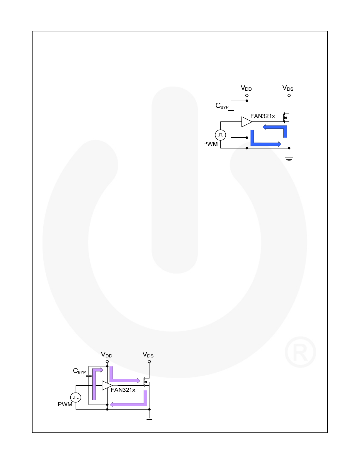
Figure 29 shows the pulsed gate drive current path
when the gate driver is supplying gate charge to turn the
MOSFET on. The current is supplied from the local
bypass capacitor, C
the MOSFET gate and to ground. To reach the high
peak currents possible, the resistance and inductance in
the path should be minimized. The localized C
to contain the high peak current pulses within this driverMOSFET circuit, preventing them from disturbing the
sensitive analog circuitry in the PWM controller.
, and flows through the driver to
BYP
BYP
acts
FAN3213 / FAN3214 — Dual-4A, High-Speed, Low-Side Gate Drivers
Figure 30 shows the current path when the gate driver
turns the MOSFET OFF. Ideally, the driver shunts the
current directly to the source of the MOSFET in a small
circuit loop. For fast turn-off times, the resistance and
inductance in this path should be minimized.
Figure 30. Current Path for MOSFET Turn-Off
Figure 29. Current Path for MOSFET Turn-On
© 2008 Fairchild Semiconductor Corporation www.fairchildsemi.com
FAN3213 / FAN3214 • Rev. 1.0.4 12
Page 13
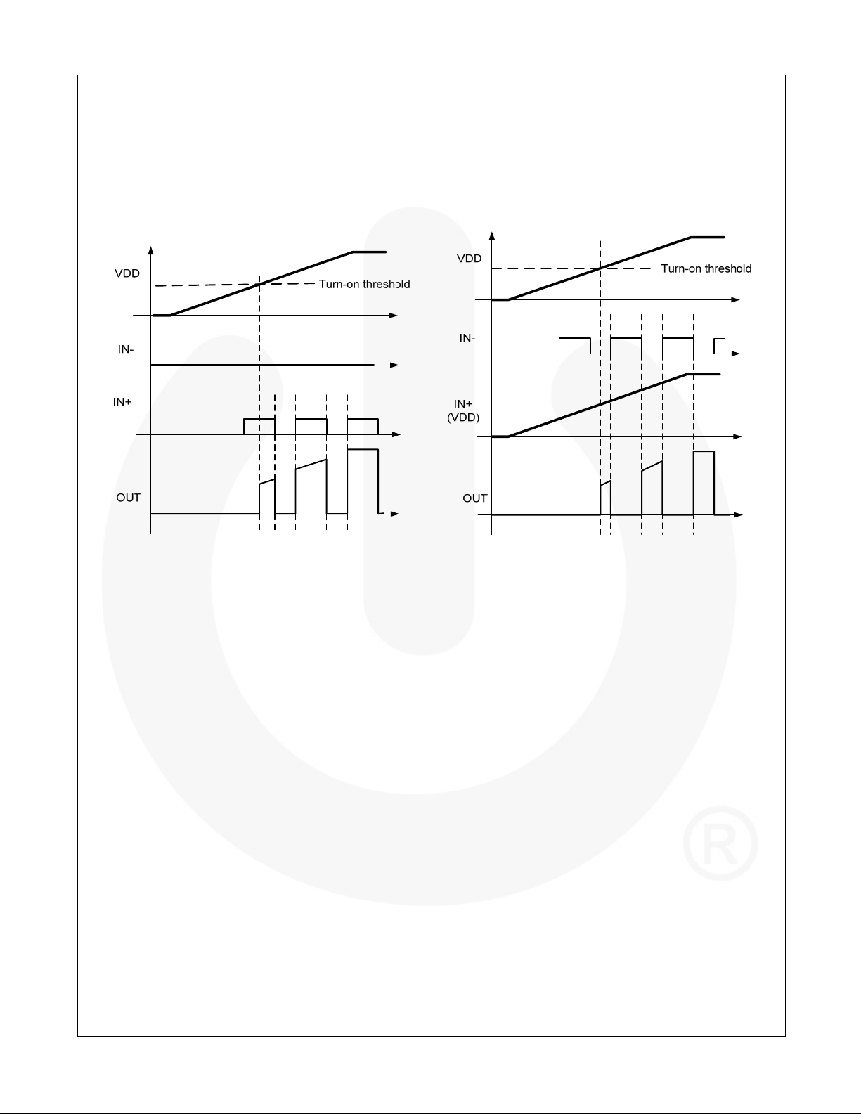
Operational Waveforms
At power-up, the driver output remains LOW until the
voltage reaches the turn-on threshold. The
V
DD
magnitude of the OUT pulses rises with V
steady-state V
is reached. The non-inverting
DD
operation illustrated in Figure 31 shows that the output
remains LOW until the UVLO threshold is reached, then
the output is in-phase with the input.
until
DD
The inverting configuration of startup waveforms are
shown in Figure 32. With IN+ tied to VDD and the input
signal applied to IN–, the OUT pulses are inverted with
respect to the input. At power-up, the inverted output
remains LOW until the V
threshold, then it follows the input with inverted phase.
voltage reaches the turn-on
DD
FAN3213 / FAN3214 — Dual-4A, High-Speed, Low-Side Gate Drivers
Figure 31. Non-Inverting Startup Waveforms
Figure 32. Inverting Startup Waveforms
© 2008 Fairchild Semiconductor Corporation www.fairchildsemi.com
FAN3213 / FAN3214 • Rev. 1.0.4 13
Page 14

Thermal Guidelines
Gate drivers used to switch MOSFETs and IGBTs at
high frequencies can dissipate significant amounts of
power. It is important to determine the driver power
dissipation and the resulting junction temperature in the
application to ensure that the part is operating within
acceptable temperature limits.
The total power dissipation in a gate driver is the sum of
+ P
GATE
DYNAMIC
and P
(1)
two components, P
P
= P
TOTAL
GATE
Gate Driving Loss: The most significant power loss
results from supplying gate current (charge per unit
time) to switch the load MOSFET on and off at the
switching frequency. The power dissipation that
results from driving a MOSFET at a specified gatesource voltage, VGS, with gate charge, QG, at
switching frequency, f
P
= QG • VGS • fSW • n (2)
GATE
, is determined by:
SW
where n is the number of driver channels in use (1 or 2).
Dynamic Pre-Drive / Shoot-through Current: A power
loss resulting from internal current consumption under
dynamic operating conditions, including pin pull-up /
pull-down resistors, can be obtained using the graphs
in Typical Performance Characteristics to determine
the current I
drawn from VDD under actual
DYNAMIC
operating conditions:
P
DYNAMIC
= I
• VDD • n (3)
DYNAMIC
Once the power dissipated in the driver is determined,
the driver junction rise with respect to circuit board can
be evaluated using the following thermal equation,
assuming
was determined for a similar thermal
JB
design (heat sinking and air flow):
TJ = P
TOTAL
•
+ TB (4)
JB
where:
= driver junction temperature;
T
J
= (psi) thermal characterization parameter
JB
relating temperature rise to total power
dissipation; and
= board temperature in location as defined in
T
B
the Thermal Characteristics table.
DYNAMIC
:
To give a numerical example, if the synchronous
rectifier switches in the forward converter of Figure 33
are FDMS8660S, the datasheet gives a total gate
charge of 60nC at V
would have 120nC gate charge. At a switching
frequency of 300kHz, the total power dissipation is:
P
= 120nC • 7V • 300kHz • 2 = 0.504W (5)
GATE
P
P
= 7.5mA • 7V • 2 = 0.011W (6)
DYNAMIC
= 0.515W ≈ 0.52W (7)
TOTAL
The SOIC-8 has a junction-to-board thermal
characterization parameter of
system application, the localized temperature around
the device is a function of the layout and construction of
the PCB along with airflow across the surfaces. To
ensure reliable operation, the maximum junction
temperature of the device must be prevented from
exceeding the maximum rating of 150°C; with 80%
derating, T
would be limited to 120°C. Rearranging
J
Equation 4 determines the board temperature required
to maintain the junction temperature below 120°C:
T
= TJ - P
B,MAX
T
= 120°C – 0.52W • 42°C/W = 98°C (9)
B,MAX
= 7V, so two devices in parallel
GS
= 42°C/W. In a
JB
•
TOTAL
(8)
JB
FAN3213 / FAN3214 — Dual-4A, High-Speed, Low-Side Gate Drivers
© 2008 Fairchild Semiconductor Corporation www.fairchildsemi.com
FAN3213 / FAN3214 • Rev. 1.0.4 14
Page 15
r
Typical Application Diagrams
FAN3213 / FAN3214 — Dual-4A, High-Speed, Low-Side Gate Drivers
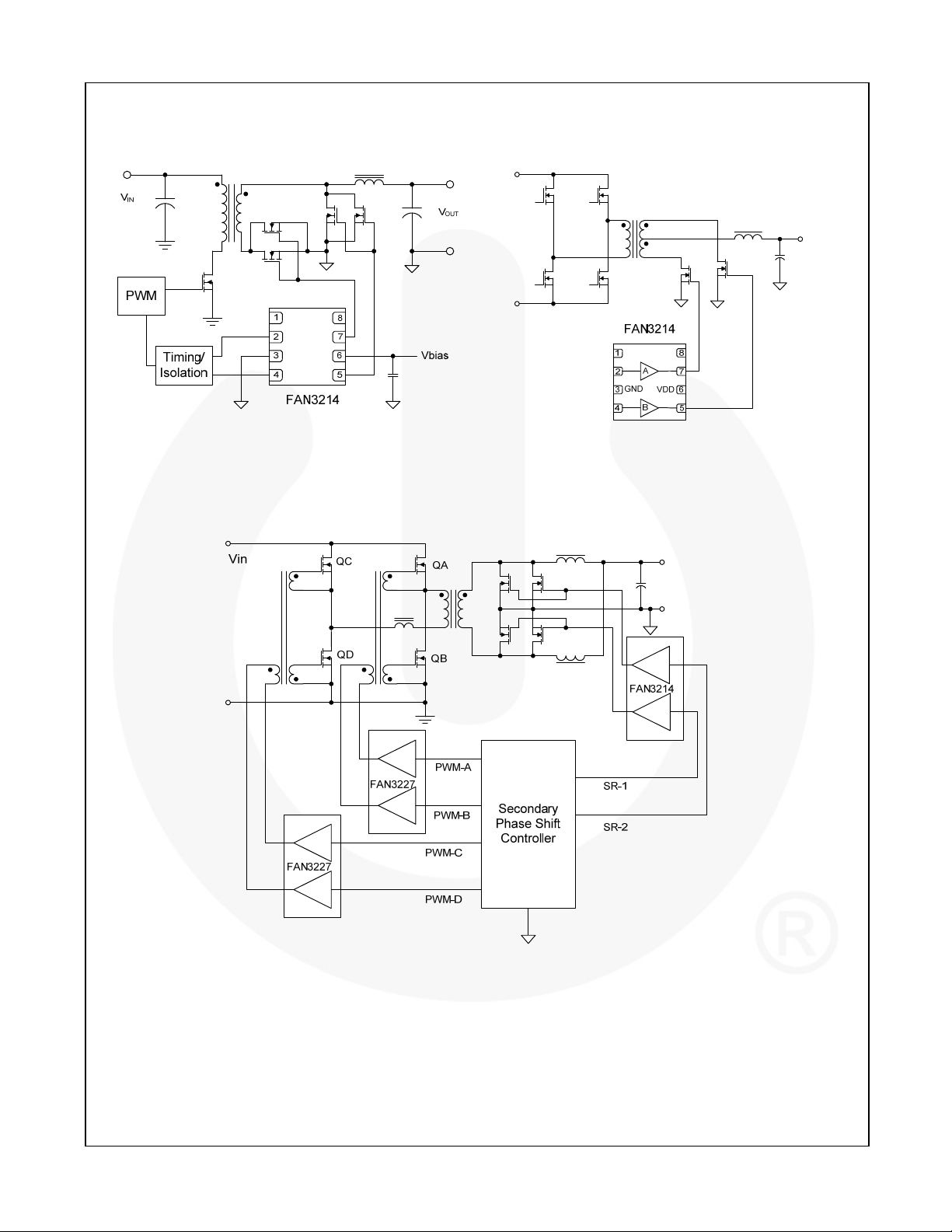
Figure 33. High-Current Forward Converter
with Synchronous Rectification
Figure 34. Cente
-Tapped Bridge Output with
Synchronous Rectifiers
Figure 35. Secondary Controlled Full Bridge with Current Doubler Output,
Synchronous Rectifiers (Simplified)
© 2008 Fairchild Semiconductor Corporation www.fairchildsemi.com
FAN3213 / FAN3214 • Rev. 1.0.4 15
Page 16
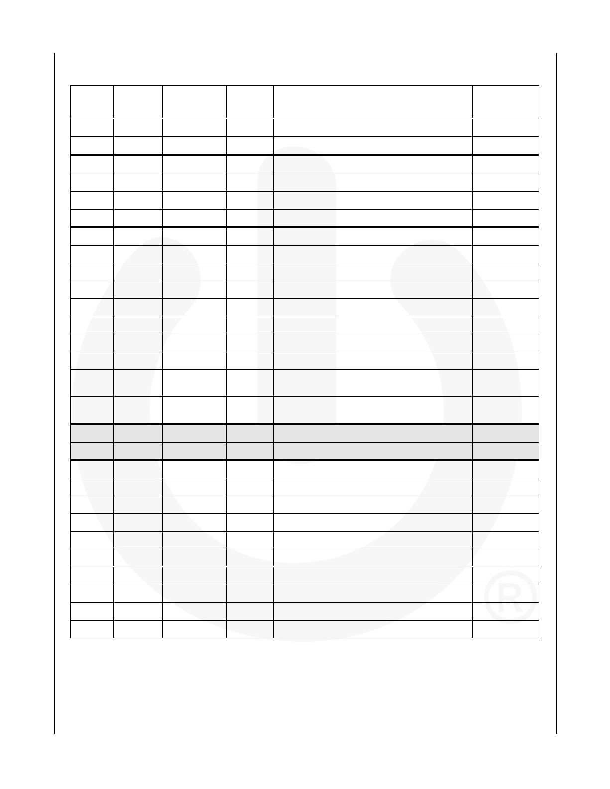
Table 1. Related Products
(12)
Type
Single 1A FAN3111C +1.1A / -0.9A CMOS Single Channel of Dual-Input/Single-Output SOT23-5, MLP6
Single 1A FAN3111E +1.1A / -0.9A External
Single 2A FAN3100C +2.5A / -1.8A CMOS Single Channel of Two-Input/One-Output SOT23-5, MLP6
Single 2A FAN3100T +2.5A / -1.8A TTL Single Channel of Two-Input/One-Output SOT23-5, MLP6
Dual 2A FAN3216T +2.5A / -1.8A TTL Dual Inverting Channels SOIC8
Dual 2A FAN3217T +2.5A / -1.8A TTL Dual Non-Inverting Channels SOIC8
Dual 2A FAN3226C +2.4A / -1.6A CMOS Dual Inverting Channels + Dual Enable SOIC8, MLP8
Dual 2A FAN3226T +2.4A / -1.6A TTL Dual Inverting Channels + Dual Enable SOIC8, MLP8
Dual 2A FAN3227C +2.4A / -1.6A CMOS Dual Non-Inverting Channels + Dual Enable SOIC8, MLP8
Dual 2A FAN3227T +2.4A / -1.6A TTL Dual Non-Inverting Channels + Dual Enable SOIC8, MLP8
Dual 2A FAN3228C +2.4A / -1.6A CMOS Dual Channels of Two-Input/One-Output, Pin Config.1 SOIC8, MLP8
Dual 2A FAN3228T +2.4A / -1.6A TTL Dual Channels of Two-Input/One-Output, Pin Config.1 SOIC8, MLP8
Part
Number
Gate Drive
(Sink/Src)
Input
Threshold
(13)
Logic Package
Single Non-Inverting Channel with External Reference SOT23-5, MLP6
FAN3213 / FAN3214 — Dual-4A, High-Speed, Low-Side Gate Drivers
Dual 2A FAN3229C +2.4A / -1.6A CMOS Dual Channels of Two-Input/One-Output, Pin Config.2 SOIC8, MLP8
Dual 2A FAN3229T +2.4A / -1.6A TTL Dual Channels of Two-Input/One-Output, Pin Config.2 SOIC8, MLP8
Dual 2A FAN3268T +2.4A / -1.6A TTL
Dual 2A FAN3278T +2.4A / -1.6A TTL
Dual 4A FAN3213T +2.5A / -1.8A TTL Dual Inverting Channels SOIC8
Dual 4A FAN3214T +2.5A / -1.8A TTL Dual Non-Inverting Channels SOIC8
Dual 4A FAN3223C +4.3A / -2.8A CMOS Dual Inverting Channels + Dual Enable SOIC8, MLP8
Dual 4A FAN3223T +4.3A / -2.8A TTL Dual Inverting Channels + Dual Enable SOIC8, MLP8
Dual 4A FAN3224C +4.3A / -2.8A CMOS Dual Non-Inverting Channels + Dual Enable SOIC8, MLP8
Dual 4A FAN3224T +4.3A / -2.8A TTL Dual Non-Inverting Channels + Dual Enable SOIC8, MLP8
Dual 4A FAN3225C +4.3A / -2.8A CMOS Dual Channels of Two-Input/One-Output SOIC8, MLP8
Dual 4A FAN3225T +4.3A / -2.8A TTL Dual Channels of Two-Input/One-Output SOIC8, MLP8
Single 9A FAN3121C +9.7A / -7.1A CMOS Single Inverting Channel + Enable SOIC8, MLP8
Single 9A FAN3121T +9.7A / -7.1A TTL Single Inverting Channel + Enable SOIC8, MLP8
Single 9A FAN3122T +9.7A / -7.1A CMOS Single Non-Inverting Channel + Enable SOIC8, MLP8
Single 9A FAN3122C +9.7A / -7.1A TTL Single Non-Inverting Channel + Enable SOIC8, MLP8
20V Non-Inverting Channel (NMOS) and Inverting
Channel (PMOS) + Dual Enables
30V Non-Inverting Channel (NMOS) and Inverting
Channel (PMOS) + Dual Enables
SOIC8
SOIC8
Notes:
12. Typical currents with OUTx at 6V and V
DD=
12V.
13. Thresholds proportional to an externally supplied reference voltage.
© 2008 Fairchild Semiconductor Corporation www.fairchildsemi.com
FAN3213 / FAN3214 • Rev. 1.0.4 16
Page 17
Physical Dimensions
8
5.00
4.80
3.81
FAN3213 / FAN3214 — Dual-4A, High-Speed, Low-Side Gate Drivers
A
0.65
5
B
6.20
5.80
4.00
1.75
5.60
3.80
PIN ONE
INDICATOR
(0.33)
1
0.25
4
1.27
1.27
CMBA0.25
LAND PATTERN RECOMMENDATION
SEE DETAIL A
0.10
0.25
1.75 MAX
0.51
0.33
0.50
R0.10
0.25
R0.10
8°
0°
0.90
0.406
Package drawings are provided as a service to customers considering Fairchild components. Drawings may change in any manner
without notice. Please note the revision and/or date on the drawing and contact a Fairchild Semiconductor representative to verify or
obtain the most recent revision. Package specifications do not expand the terms of Fairchild’s worldwide terms and conditions,
specifically the warranty therein, which covers Fairchild products.
Always visit Fairchild Semiconductor’s online packaging area for the most recent package drawings:
http://www.fairchildsemi.com/packaging/
(1.04)
DETAIL A
SCALE: 2:1
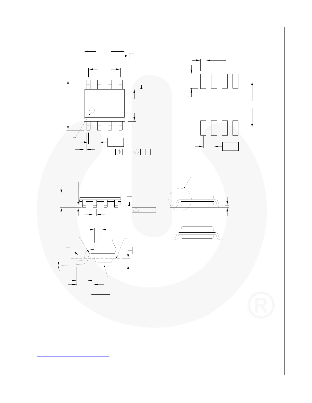
Figure 36. 8-Lead Small Outline Integrated Circuit (SOIC)
.
C
0.10 C
x 45°
GAGE PLANE
0.36
SEATING PLANE
0.19
OPTION A - BEVEL EDGE
OPTION B - NO BEVEL EDGE
NOTES: UNLESS OTHERWISE SPECIFIED
A) THIS PACKAGE CONFORMS TO JEDEC
MS-012, VARIATION AA, ISSUE C,
B) ALL DIMENSIONS ARE IN MILLIMETERS.
C) DIMENSIONS DO NOT INCLUDE MOLD
FLASH OR BURRS.
D) LANDPATTERN STANDARD: SOIC127P600X175-8M.
E) DRAWING FILENAME: M08AREV13
© 2008 Fairchild Semiconductor Corporation www.fairchildsemi.com
FAN3213 / FAN3214 • Rev. 1.0.4 17
Page 18
FAN3213 / FAN3214 — Dual-4A, High-Speed, Low-Side Gate Drivers
© 2008 Fairchild Semiconductor Corporation www.fairchildsemi.com
FAN3213 / FAN3214 • Rev. 1.0.4 18
 Loading...