

Page 1
Vishay Roederstein
AC-Capacitors, Suppression Capacitors
F1779
Class X2 AC 275 V
Dimensions in mm
L Max.
P
PCM
(mm)
PITCH CODE
POS. 10
15 F 0.5
22.5 I 0.5
27.5 K 0.5
37.5 P 0.5
LEAD LENGTH ORDERING CODE*
X (mm)
30
40
50
60
80
100
150
Dielectric
CODE POS. 12 1-4 5-7 8 9 10 11-13
+5
+5
+5
+5
+5
+10
+10
A1779. . ..2.A 0 0
B1779. . ..2.B 0 0
C1779. . ..2.C 0 0
E1779. . ..2.E 0 0
D1779. . ..2.D 0 0
L 1779 . . . . 2 . L 0 0
R1779. . ..2.R 0 0
Electrode
MAXIMUM PULSE RISE TIME: (du/dt) in V/µs
RATED
VOLTAGE
15.0 22.5 27.5
AC 275V 200 150 100
PITCH (mm)
RATED VOLTAGE:
AC 275 V, 50/60 Hz
PERMISSIBLE DC VOLTAGE:
DC 630 V
TERMINALS:
Insulated stranded copper wire, type LiY 0.5 mm2 (or AWG 20)
ends stripped and tinned
COATING:
Plastic case, epoxy resin sealed, flame retardant UL 94V-0
CLIMATIC TESTING CLASS ACC. TO EN 60068-1:
40/100/56
FURTHER TECHNICAL DATA:
See page 21 (Document No 26504)
W Max.
5.0 + 2.0
TERMINAL Ø d
H Max.
X
(mm)
Free margin
(Code pos. 9 = 2) (MKT)
FEATURES:
Product is completely lead (Pb)-free
Product is RoHS compliant
CAPACITANCE RANGE:
E12 series 0.01 µFX2 - 2.2 µFX2
preferred values acc. to E6
CAPACITANCE TOLERANCE:
Standard: ± 20 %/ ± 10 %
DISSIPATION FACTOR TANδ:
< 0.1 % measured at 1 kHz
INSULATION RESISTANCE: FOR C ≤ 0.33 µF:
30 GΩ average value
15 GΩ minimum value
TIME CONSTANT FOR C > 0.33 µF:
10 000 sec. average value
5000 sec. minimum value
TEST VOLTAGE:
(Electrode/electrode): DC 2150 V/2 sec.
REFERENCE STANDARDS:
EN 60068-1, EN 132 400, 1994
IEC 60384-14/2, 1993; UL 1283, UL 1414
CSA 22.2 No. 8-M 86, CSA 22.2 No. 1-M 90
DIELECTRIC:
Polypropylene film
ELECTRODES:
Metal evaporated
CONSTRUCTION:
Metallized film capacitor, single design
Between interconnected terminations and case (foil method):
AC 2500 V for 2 sec. at 25 °C
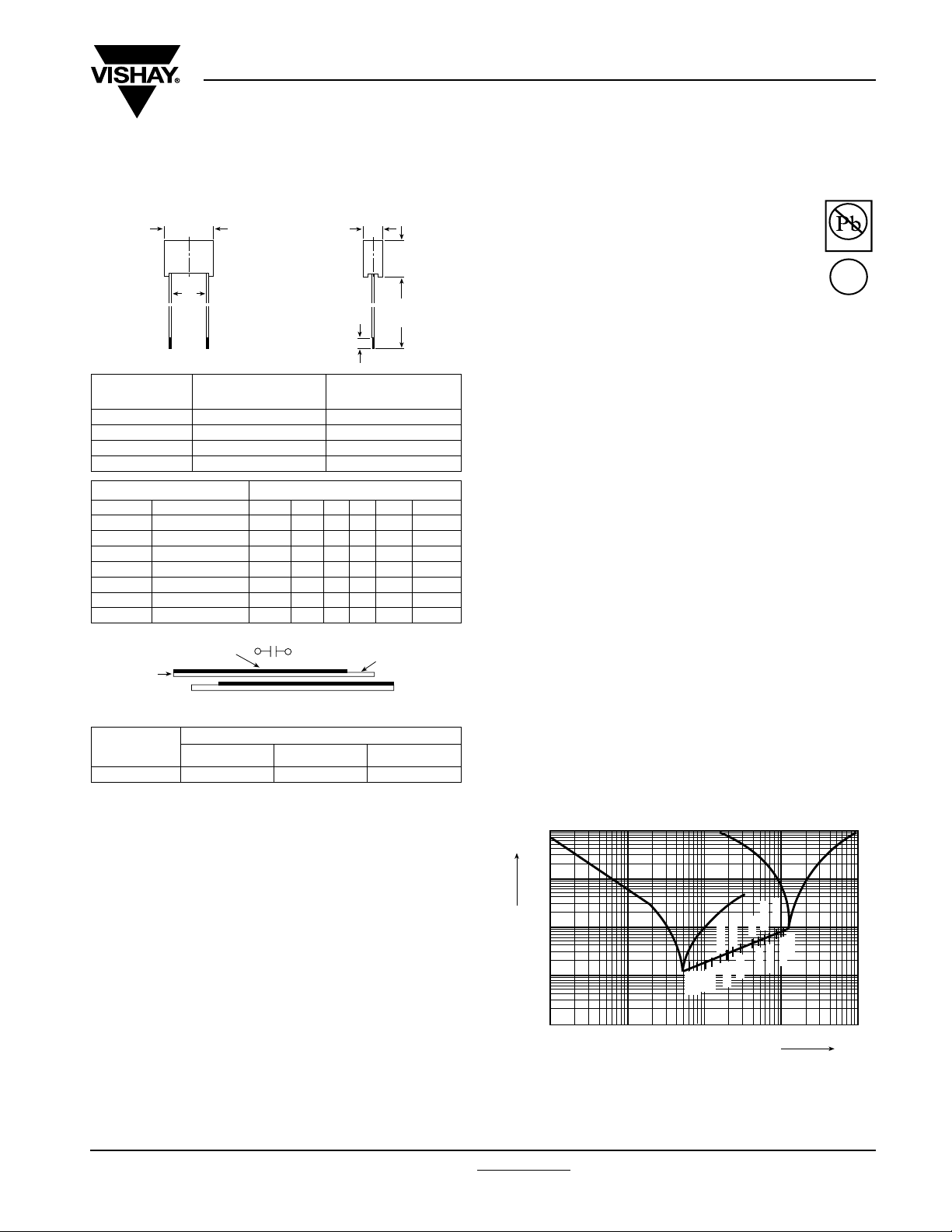
1
10
Z [Ω]
0
10
0.22 µF
0.15 µF
0.1 µF
0.068 µF
5.0
0.022 µF
0.047 µF
0.033 µF
10
f
0.01 µF
0.015 µF
-1
10
0.47 µF
-2
10
-3
10
0.01
0.05
0.1
0.5
0.33 µF
1 µF
1.5 µF
2.2 µF
0.68 µF
1.0
Impedance (Z) as a function of frequency (f) at Ta = 20 °C (average).
Measurement with lead length 6 mm.
Pb-free
e3
RoHS
COMPLIANT
100
50
[MHz]
Document Number: 26514 To contact us: RFI@vishay.com
www.vishay.com
Revision: 01-May-06 25
Page 2
F1779
Vishay Roederstein
AC-Capacitors, Suppression Capacitors
Class X2 275 V (Code pos. 9 = 2) (MKT)
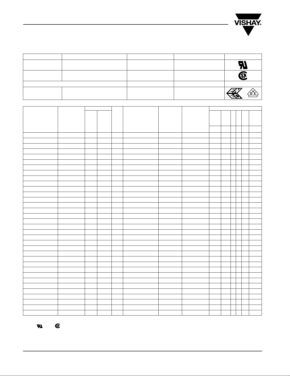
APPROVALS
COUNTRY SPECIFICATION ELECTRICAL VALUES APPROVAL REFERENCE APPROVAL MARK
U.S.A.
(for AC 250 V)
Canada
(for AC 250 V)
CB TEST-CERTIFICATE (for AC 275 V) 0.01 - 2.2 µFX2 DE 1-8222
Germany
CAPACITANCE
CODE POS. 5-7
0.047 µFX2 K/M 15.0 F 05 5.3 x 10.3 x 17.8 2.6 1000 1779 347 . 2 F . 00
0.056 µFX2 K 15.0 F 05 5.3 x 10.3 x 17.8 2.6 1000 1779 356 K 2 F . 00
0.068 µFX2 K/M 15.0 F 05 6.0 x 12.0 x 17.9 3.2 900 1779 368 . 2 F . 00
0.082 µFX2 K 15.0 F 49 6.0 x 12.0 x 17.9 3.2 900 1779 382 K 2 F . 00
0.1 µFX2 M 10.0 D 91 6.4 x 12.5 x 12.8 3.0 900 1779 410 K 2 D . 00
0.1 µFX2 K/M 15.0 F 49 6.0 x 12.0 x 17.9 3.2 900 1779 410 M 2 F . 00
0.12 µFX2 K 15.0 F 07 7.3 x 13.3 x 17.8 3.6 800 1779 412 K 2 F . 00
0.15 µFX2 K/M 15.0 F 07 7.3 x 13.3 x 17.8 3.6 800 1779 415 M 2 F . 00
0.15 µFX2 K/M 22.5 I 09 6.3 x 14.3 x 26.3 4.5 650 1779 415 M 2 I . 00
0.18 µFX2 K 15.0 F 28 8.3 x 17.3 x 17.8 4.7 600 1779 418 K 2 F . 00
0.22 µFX2 K 15.0 F 28 8.3 x 17.3 x 17.8 4.7 600 1779 422 K 2 F . 00
0.22 µFX2 M 15.0 F 28 8.3 x 17.3 x 17.8 4.7 600 1779 422 M 2 F . 00
0.22 µFX2 K/M 22.5 I 11 7.3 x 15.3 x 26.3 5.3 500 1779 422 . 2 I . 00
0.22 µFX2 M 22.5 I 09 6.3x 14.3 x 26.3 3.2 650 1779 422 M 2 I . 00
0.27 µFX2 K 22.5 I 12 8.3 x 16.3 x 26.3 4.8 500 1779 427 K 2 I . 00
0.33 µFX2 K 15.0 F 35 10.3 x 17.3 x 17.9 7.7 750 1779 433 K 2 F . 00
0.33 µFX2 M 15.0 F 46 10.0 x 16.0 x 17.9 7.4 750 1779 433 M 2 F . 00
0.33 µFX2 K/M 22.5 I 12 8.3 x 16.3 x 26.3 5.8 500 1779 433 M 2 I . 00
0.39 µFX2 K 22.5 I 01 8.3 x 16.3 x 26.3 6.7 500 1779 439 K 2 I . 00
0.47 µFX2 M 15.0 F 70 10.8 x 18.3 x 17.8 7.6 750 1779 447 M 2 F . . 0
0.47 µFX2 K/M 22.5 I 01 8.8 x 16.8 x 26.3 6.9 500 1779 447 . 2 I . 00
0.47 µFX2 K/M 27.5 K 23 8.8 x 16.3 x 31.3 8.0 500 1779 447 . 2 K . 00
0.56 µFX2 K 27.5 K 29 8.8 x 18.3 x 31.3 10.3 350 1779 456 K 2 K . 00
0.68 µFX2 K/M 22.5 I 45 10.8 x 20.8 x 26.3 9.0 500 1779 468 . 2 I . 00
0.68 µFX2 K/M 27.5 K 14 11.0 x 20.3 x 31.3 10.2 250 1779 468 . 2 K . 00
0.82 µFX2 K 27.5 K 14 11.0 x 20.3 x 31.3 10.2 300 1779 482 K 2 K . 00
1.0 µFX2 M 22.5 I 25 12.3 x 22.3 x 26.3 12.2 500 1779 510 M 2 I . 00
1.0 µFX2 K 27.5 K 15 13.0 x 23.3 x 31.3 14.1 300 1779 510 K 2 K . 00
1.0 µFX2 M 27.5 K 14 11.0 x 20.3 x 31.3 9.1 125 1779 510 M 2 K . . 0
1.2 µFX2 K 27.5 K 15 13.0 x 23.3 x 31.3 14.1 250 1779 512 K 2 K . 00
1.5 µFX2 K/M 27.5 K 18 14.5 x 24.3 x 31.3 16.2 250 1779 515 M 2 K . 00
1.8 µFX2 K 27.5 K 40 17.8 x 32.3 x 31.3 25.6 150 1779 518 K 2 K . 00
2.2 µFX2 K/M 27.5 K 40 17.8 x 32.4 x 31.2 25.6 80 1779 522 . 2 K . 00
2.2 µFX2 M 27.5 K 70 16.3 x 29.3 x 31.3 22.0 750 1779 447 M 2 F
Inbuilt discharging resistor on request (with larger case dimensions).
* With and mark, the ordering code is a 4 on digit 12.
Ordering example: 1779 410 M 2 F D40
IEC 60384-14, 2nd edition; 1995-06
TOL.
CODE POS. 8
K = ± 10 %
M = ± 20 %
(mm)
UL 1283
UL 1414
C 22.2 No. 8-M 1986
C 22.2 No. 1-M 1994
EN 132 400; 1999-06
PITCH
CODE
(mm)
POS.
10
BOX
NO.
0.01 - 2.2 µFX
0.01 - 1.0 µFX
0.01 - 2.2 µFX
0.01 - 1.0 µFX
0.01 - 4.7 µFX2 40000787
WEIGHT
DIMENSIONS
W x H x L
(+ 0.2/- 0.4 mm)
LEAD
LENGTH
D = 80 mm
(g)
E 76297
Pending
Pending
Pending
QUANTITY
PACKAGE
LEAD
LENGTH
D = 80 mm
(pcs)
10
ORDERING CODE*
TYPE
C-VALUE
TOL.
VO LTAG
PITCH
1-4 5-7 8 9 10 11-13
LEAD
. 00
LENGTH
DESIGN
www.vishay.com Document Number: 26514
26 Revision: 01-May-06
Page 3

Legal Disclaimer Notice
Vishay
Notice
Specifications of the products displayed herein are subject to change without notice. Vishay Intertechnology, Inc.,
or anyone on its behalf, assumes no responsibility or liability for any errors or inaccuracies.
Information contained herein is intended to provide a product description only. No license, express or implied, by
estoppel or otherwise, to any intellectual property rights is granted by this document. Except as provided in Vishay's
terms and conditions of sale for such products, Vishay assumes no liability whatsoever, and disclaims any express
or implied warranty, relating to sale and/or use of Vishay products including liability or warranties relating to fitness
for a particular purpose, merchantability, or infringement of any patent, copyright, or other intellectual property right.
The products shown herein are not designed for use in medical, life-saving, or life-sustaining applications.
Customers using or selling these products for use in such applications do so at their own risk and agree to fully
indemnify Vishay for any damages resulting from such improper use or sale.
Document Number: 91000 www.vishay.com
Revision: 08-Apr-05 1
 Loading...