

Page 1
XJ INSTRUMENT PANEL SYSTEMS 8E - 1
INSTRUMENT PANEL SYSTEMS
TABLE OF CONTENTS
page page
REMOVAL AND INSTALLATION
HEADLAMP LEVELING SWITCH..............1
REMOVAL AND INSTALLATION
HEADLAMP LEVELING SWITCH
REMOVAL
REAR FOG LAMP SWITCH..................1
INSTALLATION
(1) Install the instrument panel center bezel on
the I. P. Be certain headlamp leveling switch electrical harness is inserted through the hole in center
bezel.
(2) Connect the headlamp leveling switch electrical.
(3) Verify switch / system operation.
(4) Install the headlamp leveling switch in the
instrument panel center bezel by gently pushing
straight in.
(5) Connect the negative battery cable.
REAR FOG LAMP SWITCH
WARNING: ON VEHICLES EQUIPPED WITH AIRBAGS, REFER TO GROUP 8M - PASSIVE
RESTRAINT SYSTEMS BEFORE ATTEMPTING ANY
STEERING WHEEL, STEERING COLUMN, OR
INSTRUMENT PANEL COMPONENT DIAGNOSIS OR
SERVICE. FAILURE TO TAKE THE PROPER PRECAUTIONS COULD RESULT IN ACCIDENTAL AIRBAG DEPLOYMENT AND POSSIBLE PERSONAL
INJURY.
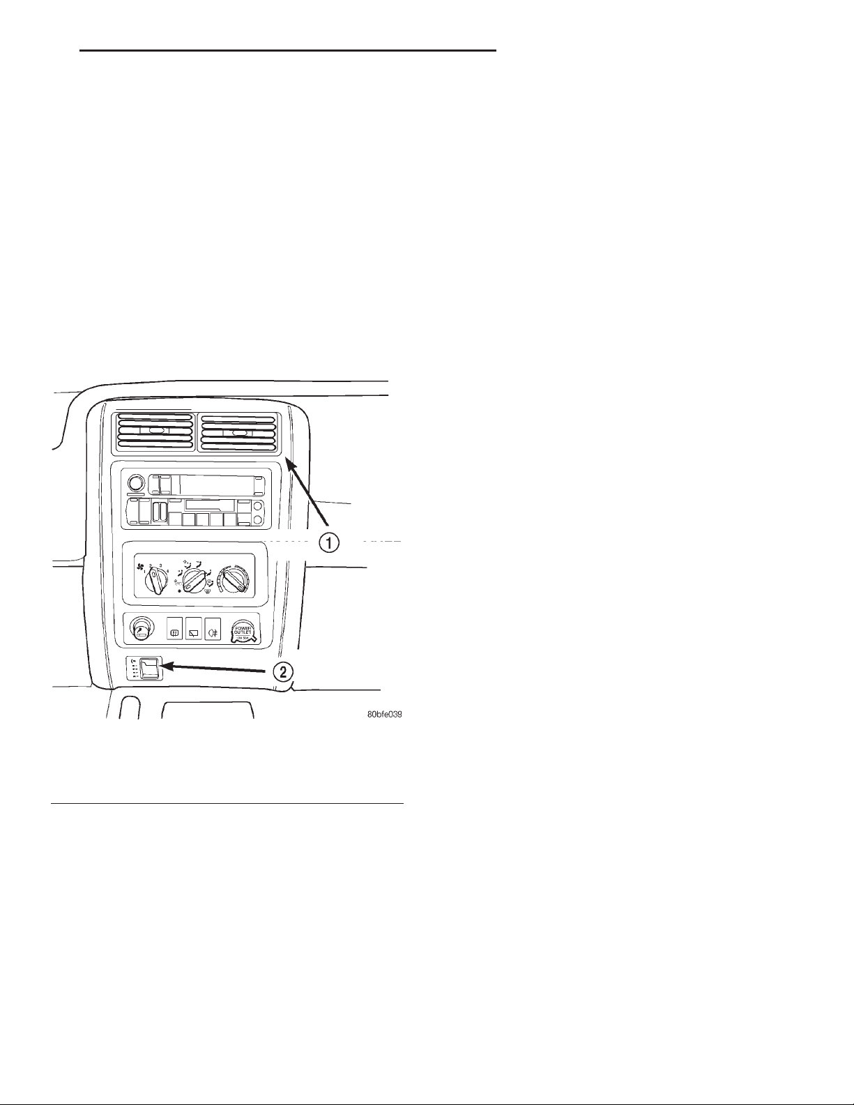
Fig. 1 Headlamp Leveling Switch Position &
Orientation
1 – INSTRUMENT PANEL CNETER BEZEL
2 – HEADLAMP LEVELING SWITCH
(1) Disconnect and isolate the negative battery
cable.
(2) Using a trim stick or another suitable wide
flat-bladed tool, gently pry the instrument panel center bezel away from the instrument panel to release
the four snap clip retainers (Fig. 1).
(3) Pull the center bezel away from the instrument
panel far enough to disconnect the wiring harness
from the headlamp leveling switch.
(4) Depress the switch retaining tabs to remove
the switch from the center bezel.
(1) Disconnect and isolate the battery negative
cable.
(2) Using a trim stick or another suitable wide
flat-bladed tool, gently pry the instrument panel center bezel away from the instrument panel to release
the six snap clip retainers.
(3) Remove the center bezel from the vehicle.
(4) Remove the three screws that secure the accessory switch bezel to the instrument panel
(5) Pull the accessory switch bezel out from the
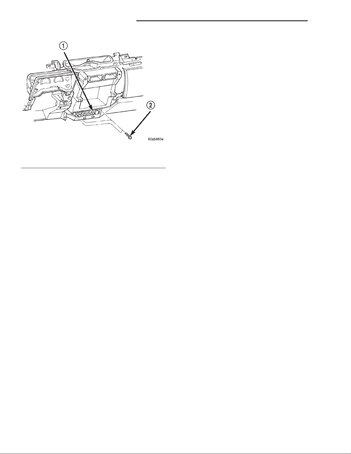
instrument panel far enough to unplug the wire harness connectors (Fig. 2).
(6) Remove the accessory switch bezel from the
instrument panel.
(7) Carefully pry the snap retainers at the top and
bottom of the rear fog lamp switch receptacle on the
back of the accessory switch bezel with a small thinbladed screwdriver and pull the switch out of the
receptacle.
Page 2
8E - 2 INSTRUMENT PANEL SYSTEMS XJ
REMOVAL AND INSTALLATION (Continued)
receptacle on the back of the accessory switch bezel
are fully engaged. Tighten the mounting screws to
2.2 N·m (20 in. lbs.).
Fig. 2 Accessory Switch Bezel Remove/Install
1 – ACCESSORY SWITCH BEZEL
2 – SCREW
(8) Reverse the removal procedures to install. Be
certain that both of the switch snap retainers in the
 Loading...