

Page 1
XJ STEERING 19 - 1
STEERING
CONTENTS
page page
POWER STEERING PUMP—2.5L VM DIESEL ... 2
POWER STEERING—2.5L VM DIESEL ........ 1
POWER STEERING—2.5L VM DIESEL
INDEX
page
GENERAL INFORMATION
POWER STEERING PUMP .................1
GENERAL INFORMATION
POWER STEERING PUMP
The power steering pump used with the 2.5L VM
Diesel engine operates the same way as the power
steering pump used with the 2.5/4.0L gasoline
engines. Refer to the Description and Operation section for the 2.5/4.0L gasoline engine power steering
pump for more information.
STEERING COLUMN ....................... 8
Page 2
19 - 2 STEERING XJ
POWER STEERING PUMP—2.5L VM DIESEL
INDEX
page page
SERVICE PROCEDURES
POWER STEERING PUMP – INITIAL
OPERATION ........................... 2
SERVICE PROCEDURES
POWER STEERING PUMP – INITIAL
OPERATION
WARNING: THE FLUID LEVEL SHOULD BE
CHECKED WITH ENGINE OFF TO PREVENT INJURY
FROM MOVING COMPONENTS.
CAUTION: Use MOPAR Power Steering Fluid or
equivalent. Do not use automatic transmission fluid
and do not overfill.
Wipe filler cap clean, then check the fluid level.
The dipstick should indicate COLD when the fluid is
at normal ambient temperature.
(1) Fill the pump fluid reservoir to the proper level
and let the fluid settle for at least two minutes.
(2) Start the engine and let run for a few seconds
then turn engine off.
(3) Add fluid if necessary. Repeat the above procedure until the fluid level remains constant after running the engine.
(4) Raise the front wheels off the ground.
(5) Slowly turn the steering wheel right and left,
lightly contacting the wheel stops at least 20 times.
(6) Check the fluid level add if necessary.
(7) Lower the vehicle, start the engine and turn
the steering wheel slowly from lock to lock.
(8) Stop the engine and check the fluid level and
refill as required.
(9) If the fluid is extremely foamy or milky looking, allow the vehicle to stand a few minutes and
repeat the procedure.
CAUTION: Do not run a vehicle with foamy fluid for
an extended period. This may cause pump damage.
REMOVAL AND INSTALLATION
POWER STEERING PUMP — LHD ...........2
POWER STEERING PUMP — RHD ........... 5
REMOVAL AND INSTALLATION
POWER STEERING PUMP — LHD
Removal
(1) Disconnect the negative battery cable.
(2) Remove the A/C line support bracket from the
rear of the rocker cover.
(3) Disconnect the A/C compressor electrical con-
nector.
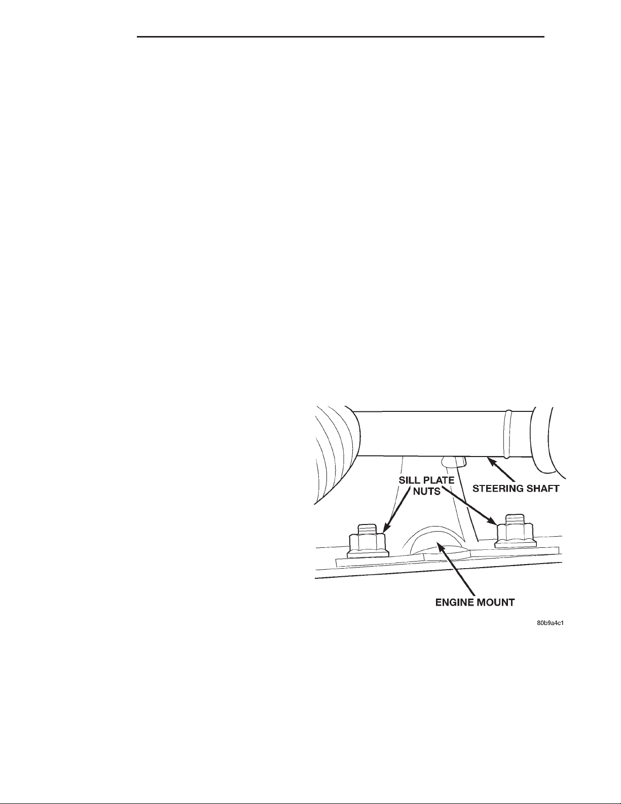
(4) Remove the (2) engine mount upper sill plate
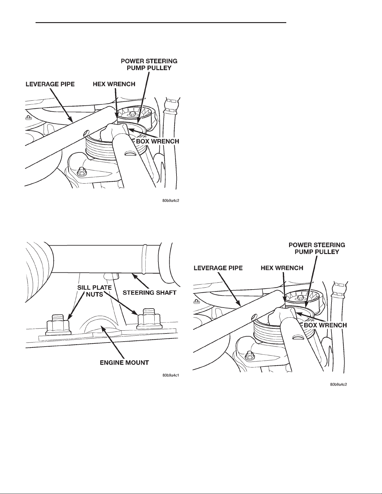
nuts (Fig. 1).
Fig. 1 Engine Mount Sill Plate Nuts
(5) Make sure the steering wheel is in the
unlocked position.
Page 3
XJ STEERING 19 - 3
REMOVAL AND INSTALLATION (Continued)
(6) Raise the vehicle on a hoist.
(7) Remove the steering shaft pinch bolt and slide
the steering shaft straight off the gearbox input
shaft, position the shaft aside.
CAUTION: Avoid turning the steering shaft while
disconnected from the steering gearbox. Damage to
steering column clockspring could occur.
(8) Remove the power steering fluid supply hose
from the pump and let the fluid drain.
(9) Loosen the (4) H-Block retaining bolts. Do not
remove the bolts at this time.
(10) Remove the accessory drive belt from the
power steering pump pulley. Refer to Group 7, Cooling System for procedure.
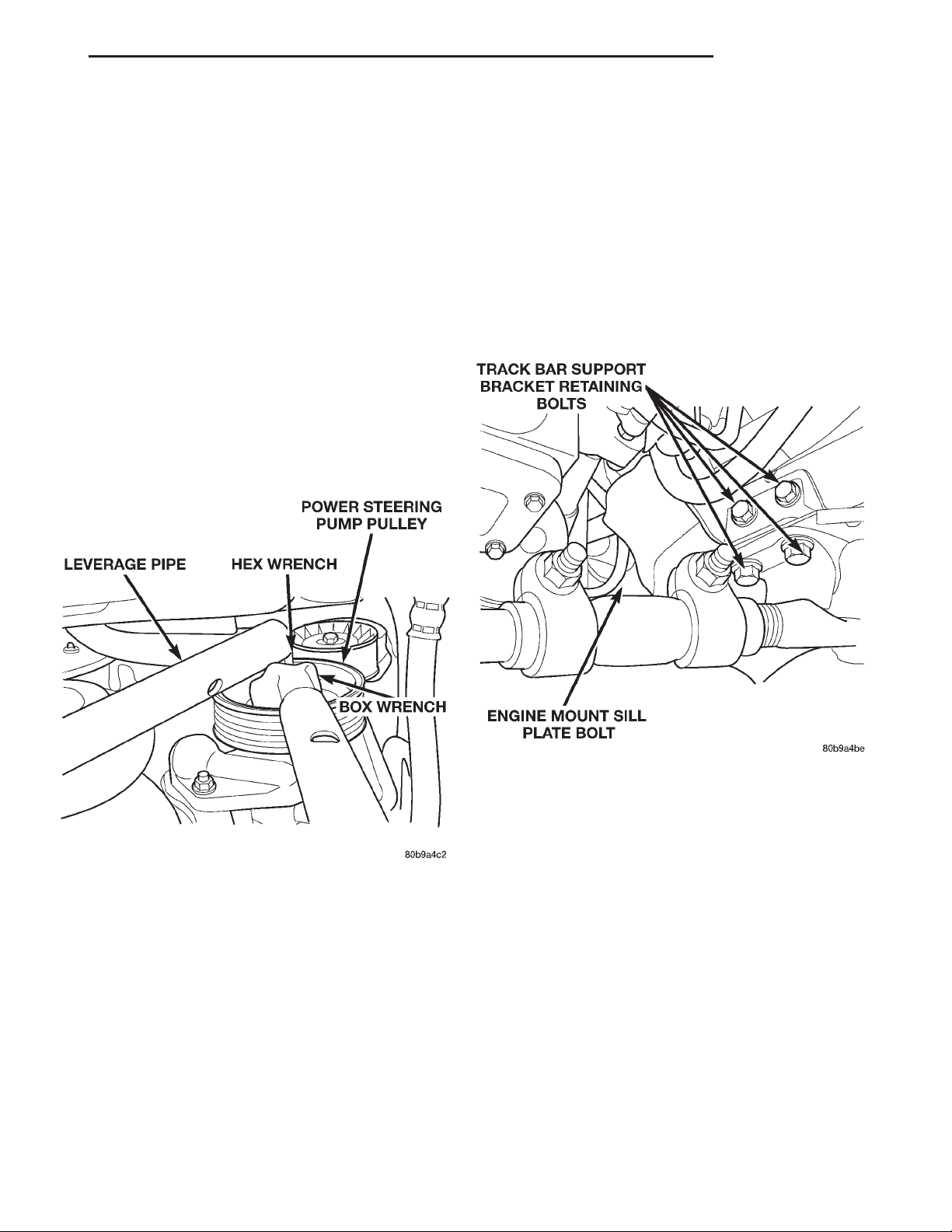
(11) Remove the power steering pump pulley. Use
a hex socket to secure the pump shaft while removing the pulley nut with a box wrench (Fig. 2).
(15) Remove the remaining 2 bolts from the
H-Block and remove the H-Block from the compressor.
(16) Support the A/C compressor with mechanics
wire before proceding to the next step.
(17) Remove the (4) A/C compressor retaining
bolts.
(18) Remove the left engine mount throughbolt nut
only. Do not remove the bolt at this time.
(19) Position a jack stand and raise weight off left
engine mount.
(20) Remove the track bar support bracket retaining bolts and remove bracket (Fig. 3).
Fig. 2 Removing the Power Steering Pump Pulley
NOTE: Mark the position of the H-Block in relation
to the A/C Compressor so it may be reinstalled in
the same position.
(12) Remove the (2) bolts retaining the H-Block to
the power steering pump shaft coupler.
(13) Loosen the coupler pinch bolt and slide the
coupler towards the pump.
(14) Remove the power steering pump pressure
line from the steering gear. This is more accessible,
but will require you to install the pressure line on
the new pump prior to installation.
Fig. 3 Engine Mount Retaining Bolts
(21) Remove the lower engine mount bolt from the
sill plate (Fig. 3).
(22) Remove the (4) engine mount bracket bolts
from the engine block.
(23) Remove the engine mount throughbolt.
(24) Remove the engine mount and engine mount
bracket from the vehicle.
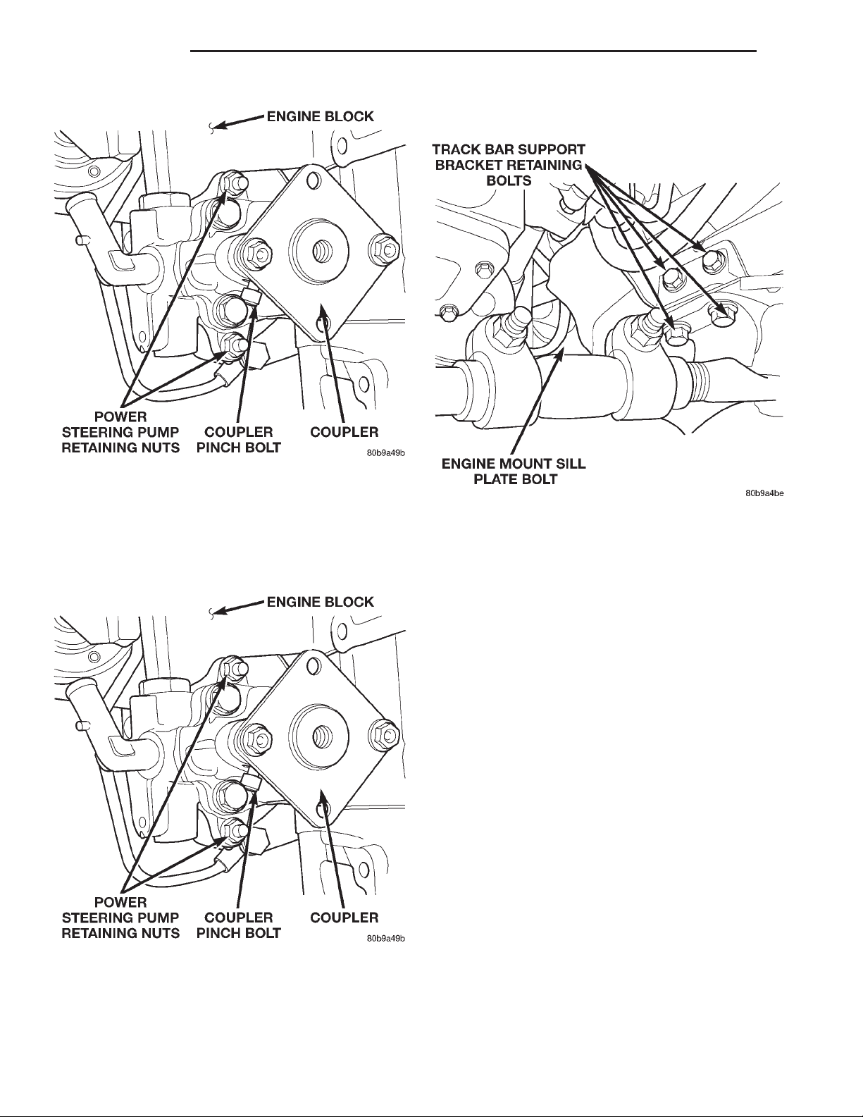
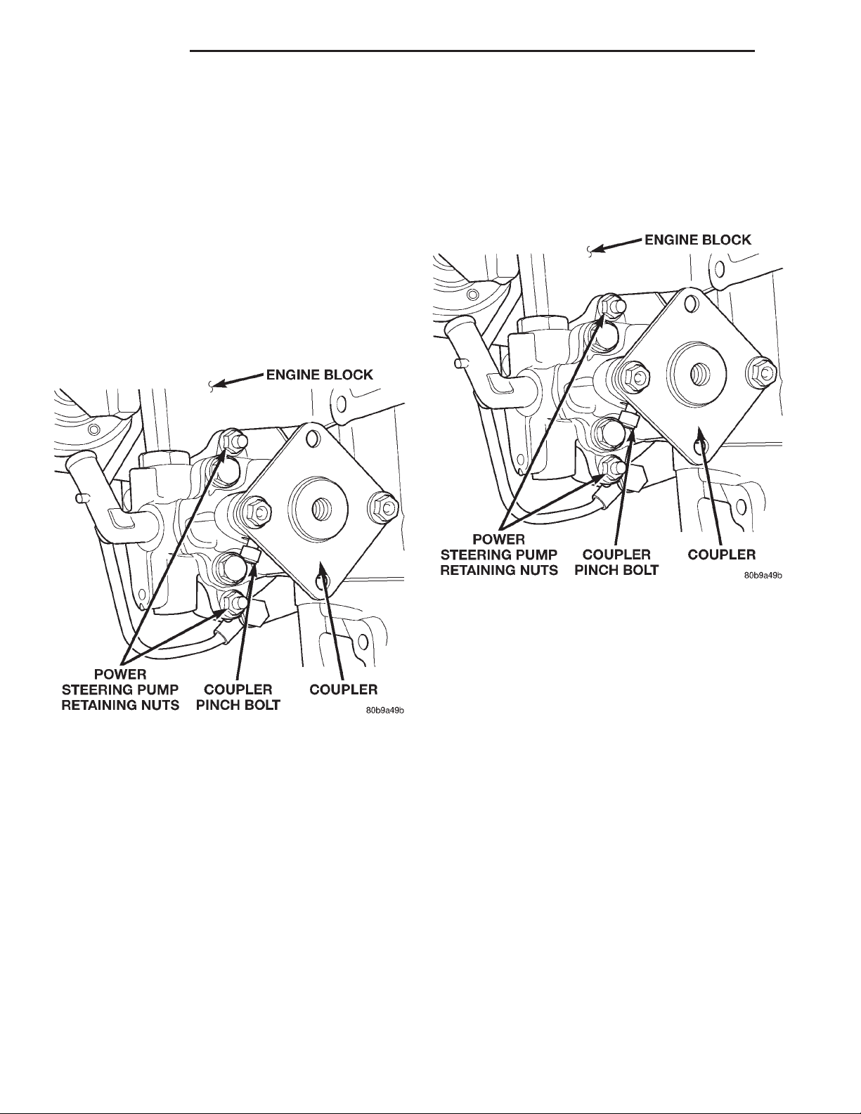
(25) Remove the (2) power steering pump retaining
nuts (Fig. 4).
(26) Remove the power steering pump from the
vehicle.
Installation
WARNING: Power steering system fluid may be
contaminated with metal shavings, overheated or
improper fluid. All fluid should be drained from the
system. After component replacement, system
should be flushed and filled with Mopar Power
Steering Fluid, or equivalent.
Page 4
19 - 4 STEERING XJ
REMOVAL AND INSTALLATION (Continued)
(6) Install, but do not torque the engine mount
and track bar support bracket bolts (Fig. 6).
Fig. 4 Power Steering Pump
(1) Transfer the pressure line to the new pump ,
making sure line is in original position.
(2) Transfer the coupler to the new pump leaving
pinch bolt lose at this time (Fig. 5).
(3) Install the power steering pump (Fig. 5).
Fig. 5 Power Steering Pump
(4) Install the engine mount and the engine mount
bracket in the vehicle.
(5) Install the engine mount throughbolt and leave
loose at this time.
Fig. 6 Engine Mount Retaining Bolts
(7) Install the (4) engine mount bracket to engine
block retaining bolts. Torque bolts to 47 N·m (35 ft.
lbs.).
(8) Torque the engine mount sill plate bolts to 41
N·m (30 ft. lbs.).
(9) Torque the larger trackbar support bracket
bolts to 125 N·m (92ft. lbs.).
(10) Remove the jack stand.
(11) Install the H-Block on the A/C compressor in
its original position and leave the bolts loose at this
time.
(12) Position and install the A/C compressor.
(13) Slide the drive coupler in its original position
and install the remaining (2) H-Block bolts.
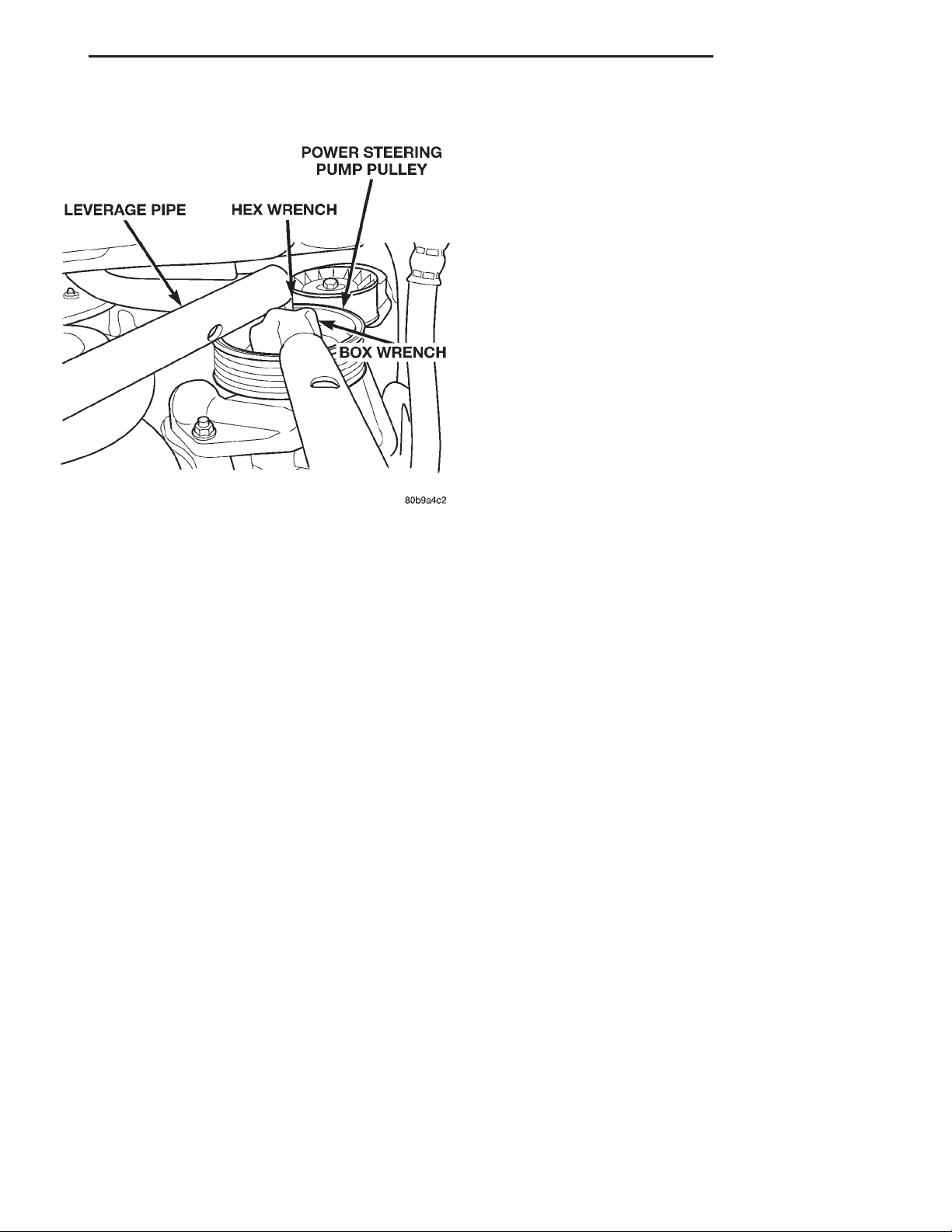
(14) Install the power steering pump pulley (Fig.
7). Torque nut to 166 N·m (120 ft. lbs.).
(15) Install the accessory drive belt. See Group 7,
Cooling System for procedure.
(16) Torque all the H-Block bolts.
(17) Install the steering shaft. Torque the steering
shaft pinch bolt to 49 N·m (36 ft. lbs.).
(18) Install the pressure line on steering gear.
Torque nut to 28 N·m (21 ft. lbs.).
(19) Install the power steering fluid supply hose on
the pump.
(20) Lower the vehicle from the hoist.
(21) Install and torque the engine mount upper sill
plate nuts to 41 N·m (30 ft. lbs.) (Fig. 8).
(22) Connect the A/C compressor electrical connector.
Page 5
XJ STEERING 19 - 5
REMOVAL AND INSTALLATION (Continued)
POWER STEERING PUMP — RHD
Removal
(1) Disconnect the negative battery cable.
(2) Remove the refrigerent line support bracket
bolt from the top of the radiator.
(3) Remove the A/C filter-drier assembly support
bracket nuts from left fender well.
(4) Disconnect the A/C compressor electrical connector.
(5) Raise the vehicle on a hoist.
(6) Remove the power steering fluid supply hose
from pump and drain fluid.
(7) Remove power steering line support bracket
bolt from below radiator.
(8) Remove the engine mount upper sill plate nuts.
(9) Loosen the (4) H-Block retaining bolts. Do not
remove at this time.
(10) Remove the accessory drive belt from the
power steering pump pulley. See Group 7, Cooling
System for procedure.
Fig. 7 Installing Pump Pulley
(11) Remove the power steering pump pulley. Use
a hex socket to secure the pump shaft while removing the pulley nut with a box wrench (Fig. 9).
Fig. 8 Engine Mount Sill Plate Nuts
(23) Install the A/C line support bracket bolt at the
rear of the valve cover.
(24) Fill the power steering fluid. See Group 19,
Steering for Power Steering Pump-Initial operation
procedure.
(25) Connect the negative battery cable.
Fig. 9 Removing Pump Pulley
NOTE: Mark position of the H-Block in relation to
the A/C Compressor so it can be installed in the
same position.
(12) Remove the (2) bolts retaining the H-Block to
the power steering pump shaft coupler.
(13) Loosen the coupler pinch bolt and slide cou-
pler towards pump.
Page 6
19 - 6 STEERING XJ
REMOVAL AND INSTALLATION (Continued)
(14) Remove the left engine mount throughbolt nut
only. Do not remove the bolt at this time.
(15) Remove the remaining 2 bolts from the
H-Block and remove the H-Block from the compressor.
(16) Position a jack stand and raise weight off left
engine mount.
(17) Remove the (2) engine mount sill plate bolts.
(18) Remove the (4) engine mount bracket bolts
from the engine block.
(19) Remove the engine mount throughbolt.
(20) Remove the engine mount and engine mount
bracket from vehicle.
(21) Remove the (2) power steering pump retaining
nuts (Fig. 10).
(1) Install the pressure line on pump in original
position.
(2) Transfer the drive coupler to new pump leaving
pinch bolt lose at this time (Fig. 11).
(3) Install the power steering pump in the engine
block. Torque retaining nuts to 24 N·m (18 ft. lbs.)
(Fig. 11).
Fig. 10 Power Steering Pump
(22) Slide pump off mounting studs and position so
pressure line can be removed. This will require you
to install pressure line on the new pump prior to
installing it in the engine block.
(23) Remove the power steering pump from the
vehicle.
Installation
WARNING: Power steering system fluid may be
contaminated with metal shavings, overheated or
improper fluid. All fluid should be drained from the
system. After component replacement, system
should be flushed and filled with Mopar Power
Steering Fluid, or equivalent.
Fig. 11 Power Steering Pump
(4) Install the engine mount and engine mount
bracket in vehicle.
(5) Install the engine mount throughbolt and leave
loose at this time.
(6) Install, do not torque engine mount sill plate
nuts and bolts.
(7) Install (4) engine mount bracket to engine
block retaining bolts and Torque to 61 N·m (45 ft.
lbs.).
(8) Torque the engine mount sill plate nuts to 41
N·m (30 ft. lbs.).
(9) Torque the engine mount sill plate bolts to 41
N·m (30 ft. lbs.).
(10) Remove jack stand.
(11) Install the H-Block on the A/C compressor in
the original position and leave bolts loose at this
time.
(12) Position and install A/C compressor.
(13) Slide the drive coupler into its original position and start remaining (2) H-Block bolts.
(14) Install the power steering pump pulley (Fig.
12). Torque nut to 166 N·m (120 ft. lbs.).
Page 7
XJ STEERING 19 - 7
REMOVAL AND INSTALLATION (Continued)
(15) Install the accessory drive belt. See Group 7,
Cooling for procedure.
(16) Torque all the H-Block bolts.
(17) Torque the engine mount throughbolt nut to
65 N·m (48 ft. lbs.).
(18) Install the power steering fluid supply hose on
pump.
(19) Install the power steering line support
bracket bolt.
(20) Lower the vehicle from hoist.
(21) Install the refrigerent line support bracket
and bolt on the top of the radiator.
(22) Install the A/C filter-drier assembly support
bracket nuts on the left fender well.
(23) Reconnect the A/C compressor electrical connector.
(24) Re-fill the power steering fluid. Refer to
Group 19, Steering for Power Steering Pump-Initial
Operation for procedure.
(25) Connect the negative battery cable.
Fig. 12 Installing Pump Pulley
Page 8
19 - 8 STEERING XJ
STEERING COLUMN
INDEX
page page
GENERAL INFORMATION
STEERING COLUMN ...................... 8
DIAGNOSIS AND TESTING
IGNITION SWITCH ........................ 9
GENERAL INFORMATION
STEERING COLUMN
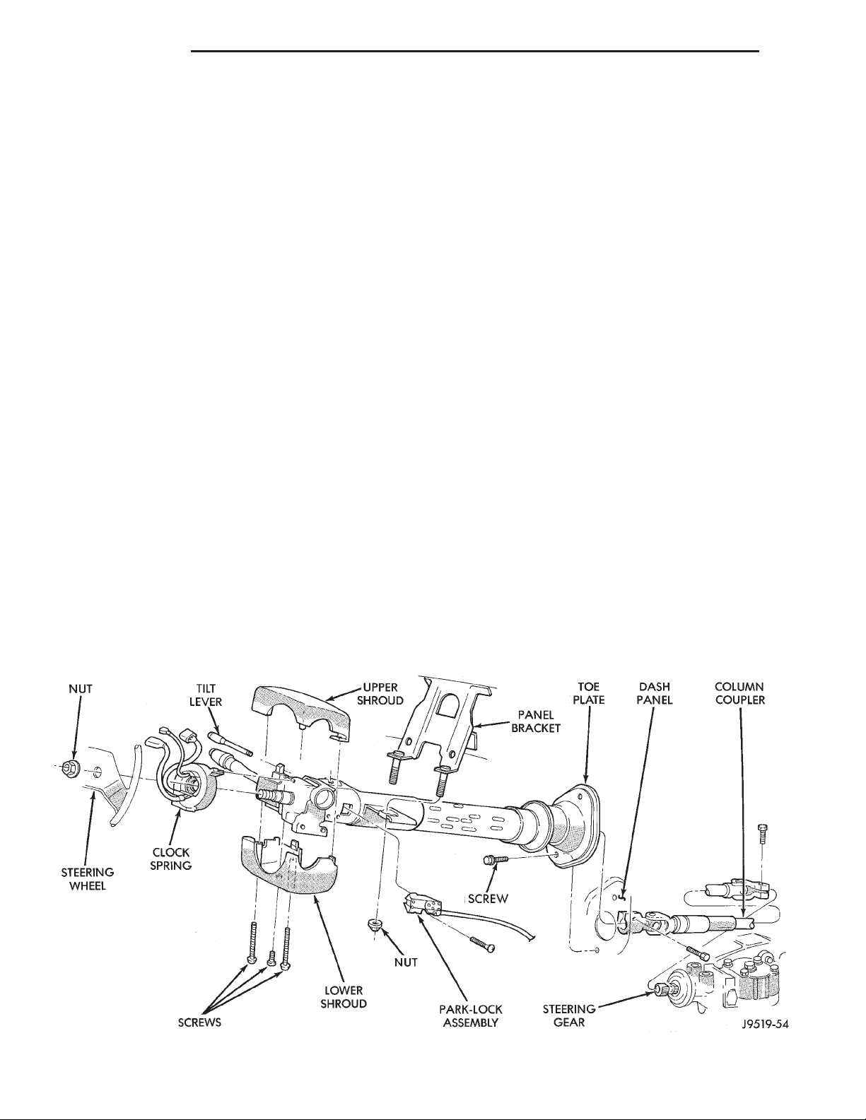
The tilt and standard column (Fig. 1) has been
designed to be serviced as an assembly; less wiring,
switches, shrouds, steering wheel, etc. Most steering
column components can be serviced without removing the steering column from the vehicle.
SERVICE PRECAUTIONS
Safety goggles should be worn at all times when
working on steering columns.
To service the steering wheel, switches or airbag,
refer to Group 8 M and follow all WARNINGS and
CAUTIONS.
WARNING: THE AIRBAG SYSTEM IS A SENSITIVE,
COMPLEX ELECTRO-MECHANICAL UNIT. BEFORE
REMOVAL AND INSTALLATION
STEERING COLUMN ...................... 9
SPECIFICATIONS
TORQUE CHART ........................ 11
ATTEMPTING TO DIAGNOSE, REMOVE OR INSTALL
THE AIRBAG SYSTEM COMPONENTS YOU MUST
FIRST DISARM THE AIRBAG FIRING MECHANISM.
FAILURE TO DO SO COULD RESULT IN ACCIDENTAL DEPLOYMENT OF THE AIRBAG AND POSSIBLE PERSONAL INJURY.
WARNING: THE FASTENERS, SCREWS, AND
BOLTS, ORIGINALLY USED FOR THE AIRBAG COMPONENTS, HAVE SPECIAL COATINGS AND ARE
SPECIFICALLY DESIGNED FOR THE AIRBAG SYSTEM. THEY MUST NEVER BE REPLACED WITH ANY
SUBSTITUTES. ANYTIME A NEW FASTENER IS
NEEDED, REPLACE WITH THE CORRECT FASTENERS PROVIDED IN THE SERVICE PACKAGE OR
FASTENERS LISTED IN THE PARTS BOOKS.
Fig. 1 Steering Column
Page 9
XJ STEERING 19 - 9
GENERAL INFORMATION (Continued)
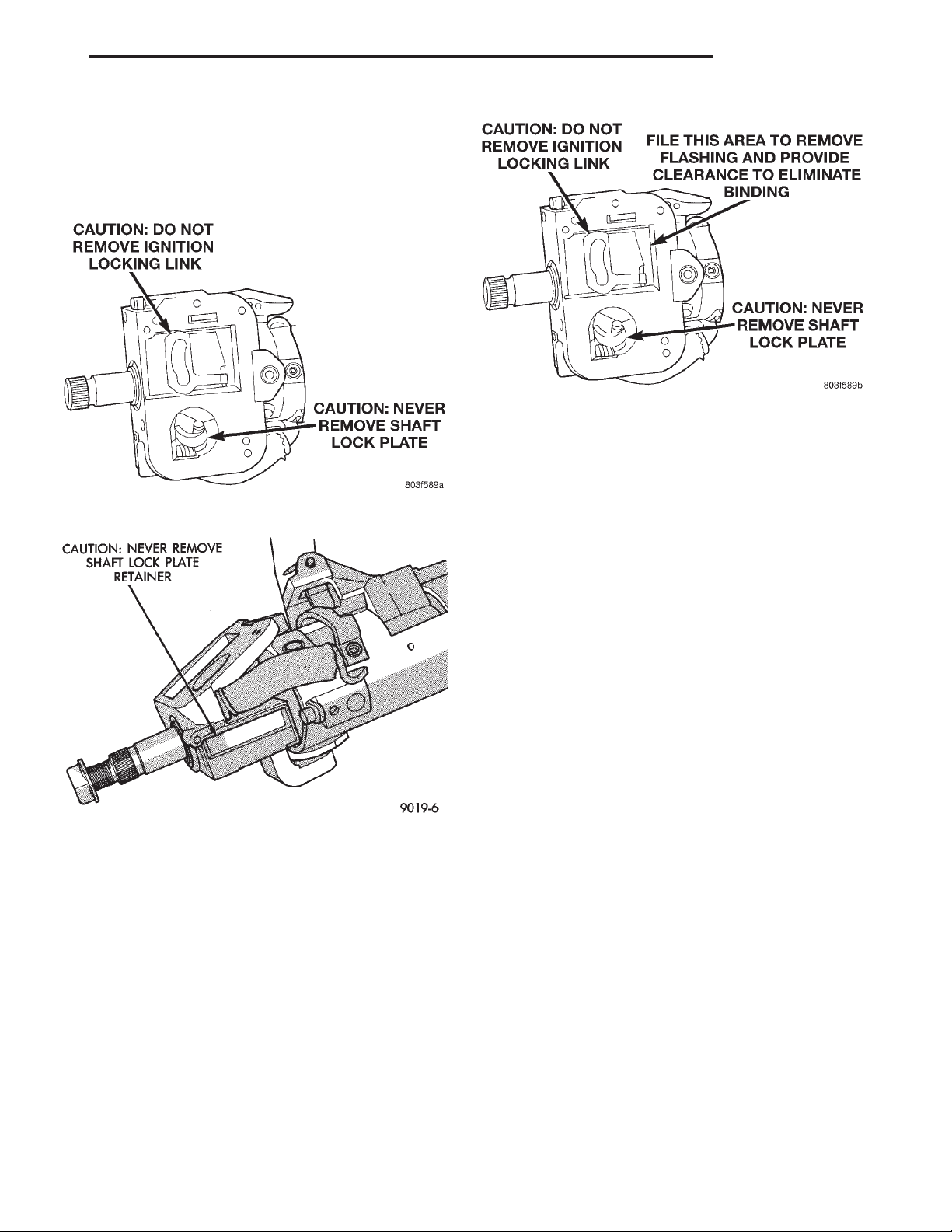
CAUTION: Do not attempt to remove the pivot pins
to disassemble the tilting mechanism. Do not
remove ignition locking link, shaft lock plate or
plate retainer. This will damage the column (Fig. 2)
and (Fig. 3).
Fig. 4 Steering Column Flash Removal And
Non-Serviceable Components
slot at any point lightly file the slider or slot until
clearance is achieved.
(3) If no binding is found, lightly file the ramp on
Fig. 2 Observe Cautions
the ignition switch, (The ramp fits into the casting)
until binding no longer occurs.
Fig. 3 Observe Cautions
DIAGNOSIS AND TESTING
IGNITION SWITCH
TEST AND REPAIR
If the ignition switch effort is excessive, remove the
ignition switch from the steering column. Refer to
Group 8D Ignition System. Using a key cylinder,
check the turning effort of the switch. If the ignition
switch binds look for the following conditions.
(1) Look for rough areas or flash in the casting
and if found remove with a file (Fig. 4).
(2) With the ignition switch removed, slide the
slider in its slot in the sleeve and verify a loose fit
over the length of the slot. If the slider binds in the
REMOVAL AND INSTALLATION
STEERING COLUMN
WARNING: BEFORE SERVICING THE STEERING
COLUMN THE AIRBAG SYSTEM MUST BE DISARMED, REFER TO GROUP 8M RESTRAINT SYSTEMS FOR SERVICE PROCEDURES. FAILURE TO
DO SO MAY RESULT IN ACCIDENTAL DEPLOYMENT OF THE AIRBAG AND POSSIBLE PERSONAL
INJURY.
REMOVAL
(1) Position the front wheels straight ahead .
(2) Remove the negative (ground) cable from the
battery.
(3) Disarm and remove airbag, steering wheel and
clockspring, refer to group 8M Restraint Systems for
service procedures.
(4) Remove lower instrument panel/knee blocker.
(5) Remove column coupler upper pinch bolt (Fig.
5).
(6) Remove relay box.
(7) Remove tilt lever (if equipped) from column.
(8) Remove upper and lower steering column
shrouds.
(9) Remove lower fixed column shroud.
(10) Remove column braces (Fig. 6).
(11) Remove column bracket mounting nuts and
lower column.
Page 10

19 - 10 STEERING XJ
REMOVAL AND INSTALLATION (Continued)
Fig. 5 Steering Column
Fig. 6 Steering Column Braces
(12) Remove upper fixed column shroud.
(13) Remove multi-function switch tamper proof
mounting screws and connector screw. Connector
screw will stay in the connector.
(14) Unplug wiring harness from the column
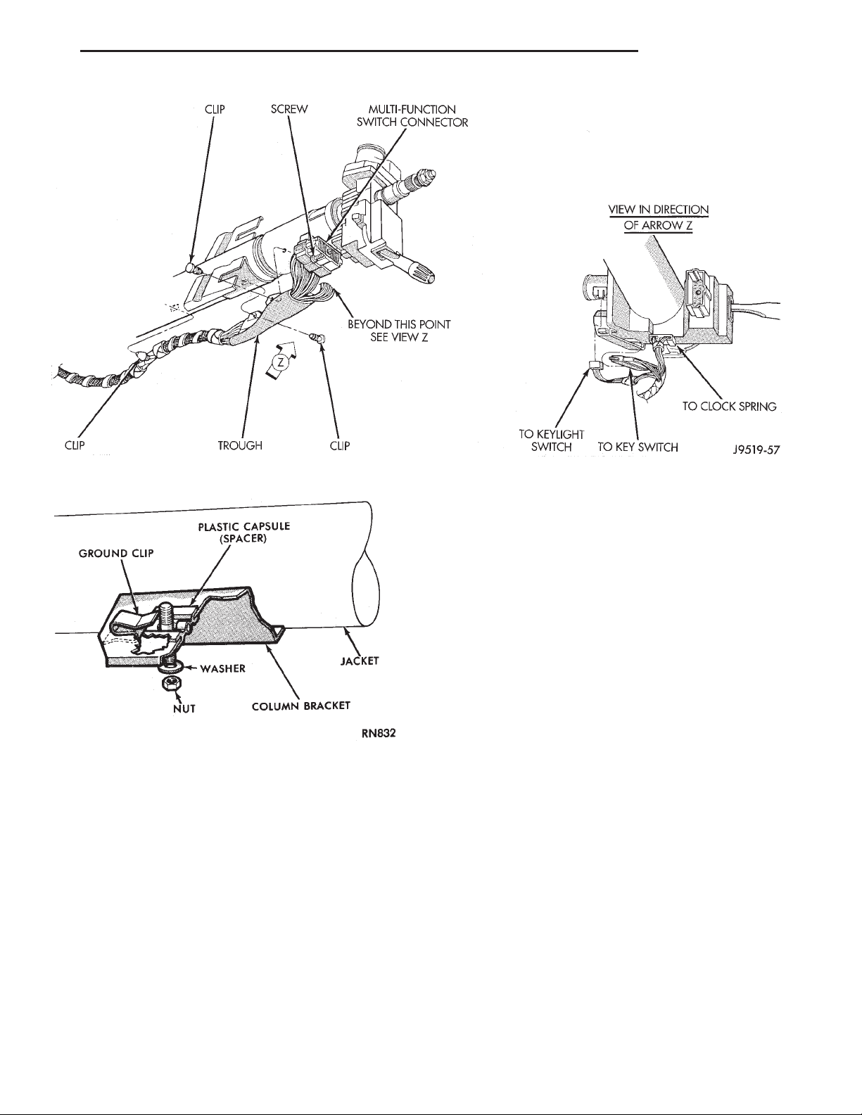
switches (Fig. 7).
(15) Remove the wiring harness from steering column.
(16) Remove ignition switch.
(17) Remove interlock cable from the steering column, refer to Group 21 Automatic Transmission
Shifter/Ignition Interlock.
(18) Remove the column.
INSTALLATION
(1) Align and install the column to the coupler. Do
not apply force at the top of the steering column shaft.
(2) Ensure the ground clip is position (Fig. 8).
(3) Install interlock cable from the steering column, refer to Group 21 Automatic Transmission
Shifter/Ignition Interlock.
(4) Install wiring harness connections to steering
column.Ensure the wiring is not pinched and all
connections are correctly locked in place.
(5) Install wiring harness connector onto multi
function switch. Tighten function switch wiring harness connector retaining bolt to 2 N·m (17 in. lbs.).
(6) Plug in wiring harness connector to remaining
switches.
(7) Install ignition switch.
(8) Install upper fixed column shroud cover.
(9) Install shaft coupler pinch bolt loose, load column up to panel bracket.
Page 11
XJ STEERING 19 - 11
REMOVAL AND INSTALLATION (Continued)
Fig. 7 Steering Column Wiring Harness
Fig. 8 Ground Clip & Spacer
(10) Be sure both spacers are fully seated in the
column support bracket. Tighten the column panel
bracket support nuts to 12 N·m (105 in. lbs.).
(11) Tighten the coupler pinch bolt to 47 N·m (35
ft. lbs.).
(12) Install lower fixed shroud.
(13) Install upper and lower shrouds. Install the
tilt lever (if equipped).
(14) Install relay box.
(15) Install lower instrument panel/knee blocker.
(16) Install clockspring, steering wheel and airbag.
Refer to Group 8M Restraint Systems for service procedures.
(17) Remove the column shaft shipping lock pin
(installed in service column).
(18) Connect the battery ground (negative) cable.
SPECIFICATIONS
TORQUE CHART
DESCRIPTION TORQUE
Tilt Steering Column
Steering Wheel Nut ........54N·m(40ft.lbs.)
Mounting Nuts ............23N·m(17ft.lbs.)
Coupler Bolt ..............49N·m(36ft.lbs.)
Non-Tilt Steering Column
Steering Wheel Nut ........54N·m(40ft.lbs.)
Mounting Nuts ............23N·m(17ft.lbs.)
Coupler Bolt ..............49N·m(36ft.lbs.)
Upper Bracket Nut ........17N·m(150 in. lbs.)
Page 12

 Loading...