

Page 1

20080310
Page 2

Table of Contents|DOP-EXIO Series
Revision March, 2008, Doc. Name: 2007PDD23000014 i
Table of Contents
Chapter 1 Getting Started .........................................................................................1-1
Chapter 2 HMI-WPLSoft Introduction........................................................................2-1
Chapter 3 Creating and Editing Programs ................................................................3-1
Chapter 4 I/O Point Indicators...................................................................................4-1
Chapter 5 Internal Memory Address .........................................................................5-1
Appendix A List of Devices......................................................................................... A-1
Appendix B List of Instructions ................................................................................... B-1
Appendix C Use of Basic Instructions......................................................................... C-1
Appendix D Use of Application Instructions ................................................................ D-1
Page 3

Table of Contents|DOP-EXIO Series
ii
Revision March, 2008, Doc. Name: 2007PDD23000014
This page intentionally left blank.
Page 4

Chapter 1 Getting Started|DOP-EXIO Series
Revision March, 2008, Doc. Name: 2007PDD23000014 1-1
Chapter 1 Getting Started
Delta Extension Digital I/O Module, DOP-EXIO14RAE and DOP-EXIO28RAE (hereinafter
called “DOP-EXIO series”) provided for DOP-AE series HMI only. Therefore, before using
Delta Extension Digital I/O Module, the user has to open the ScrEdit (Screen Editor)
programming software, click “File” > “New” to open a new project, and select the type of
DOP-AE series HMI being used (see Fig. 1.1).
Fig. 1.1 New project dialog box
After selecting the type of DOP-AE series HMI, press OK button to complet the setting. Then,
click “Options > “Configuration” to enter into “Other” tab in Configuration option (see Fig. 1.2).
Check the box next to “Enable EXIO (Compile Ladder)” to activate the function of Delta
Extension Digital I/O Module. The user can also select the digital input and output points here
by using the drop down list right below the “Enable EXIO (Compile Ladder)” option (see Fig.
1.3).
Page 5

Chapter 1 Getting Started|DOP-EXIO Series
1-2
Revision March, 2008, Doc. Name: 2007PDD23000014
Fig. 1.2 Configuration option
Page 6

Chapter 1 Getting Started|DOP-EXIO Series
Revision March, 2008, Doc. Name: 2007PDD23000014 1-3
Fig. 1.3 Other tab
When “Enable EXIO (Compile Ladder)” option is selected, the “Ladder Editor” icon will appear
and be available for use on the toolbar (See Fig. 1.4 and 1.5). The user can click this icon and
start ladder diagram editing directly or click “Tool” > “Ladder Editor” command from the menu
(See Fig. 1.6).
Fig. 1.4 Toolbar before “Enable EXIO (Compile Ladder)” option is selected
Fig. 1.5 Toolbar after “Enable EXIO (Compile Ladder)” option is selected
Page 7

Chapter 1 Getting Started|DOP-EXIO Series
1-4
Revision March, 2008, Doc. Name: 2007PDD23000014
Fig. 1.6 Ladder Editor option
Page 8

Chapter 2 HMI-WPLSoft Introduction|DOP-EXIO Series
Revision March, 2008, Doc. Name: 2007PDD23000014 2-1
Chapter 2 HMI-WPLSoft Introduction
Clicking the “Ladder Editor” icon can open HMI-WPLSoft editing window immediately
(see Fig. 2.1). At the same time, the window of ScrEdit (Screen Editor) will zoom out and hide
automatically. Please note that HMI-WPLSoft and ScrEdit programming software cannot be
used simultaneously. When the user is editing a ladder diagram and in the meantime the user
wants to edit a HMI program, the user must close the window of HMI-WPLSoft and then it is
possible for the user to edit a HMI program in the environment of ScrEdit programming
software successfully. There is no Open and Save option provided in the ladder diagrm editing
window. When the ladder diagrm editing window is closed, the ladder diagrm editing program
is saved automatically.
Fig. 2.1 HMI-WPLSoft editing window
There are five parts in the following for the window of HMI-WPLSoft.
Menu bar
There are nine functions for selection: File(F), Edit(E), Compiler(P), Comments(M),
Search(S), View(V), Options(O), Window(W), and Help(H). Each option has a pull-down
menu.
Menu Bar
Toolbar
Ladder Diagram
Editing Area
Instruction
Editing Area
Status Bar
Page 9

Chapter 2 HMI-WPLSoft Introduction|DOP-EXIO Series
2-2
Revision March, 2008, Doc. Name: 2007PDD23000014
Toolbar
There are many icons provided for the user to execute functions by clicking the mouse
directly. The followings are the available toolbar on HMI-WPLSoft.
1. Standard Toolbar
2. HMI-WPLSoft Toolbar
3. Ladder diagram Toolbar (display in Ladder Diagram Mode only)
Ladder Diagram Editing Area
This is the area for designing the editing the ladder diagram by requirement.
Instruction Editing Area
This is the area for designing the editing the instructions by requirement.
Status Bar
It is used to display messages, including replace/insert mode, the coordinate of the editing
diagram or object, etc.
2.1 File
The “File” function is shown as follows, including pull-down menu options:
Page 10

Chapter 2 HMI-WPLSoft Introduction|DOP-EXIO Series
Revision March, 2008, Doc. Name: 2007PDD23000014 2-3
Print(P) Ö Print current file (only print current window, i.e. one of ladder diagram or
instruction mode).
Method 1: Click “File(F)” > “Print (P)”.
Method 2: Click the icon from the toolbar.
Method 3: Use keyboard shortcuts by pressing keys (Ctrl) + (P).
After the editing is completed, the user can use the icon or click “File” > “Print (P)”
to print the editing program or instrucation and relevant data. In the different editing
window, the user can use Print(P) function to print the ladder diagram or instruction data.
Please refer to the following descriptions.
Print Ladder Diagram
In Ladder Diagram Mode (when the ladder diagram editing window is opened), click the
icon on toolbar or choose “Print(P)” command from the “File” menu, the print
selection dialog box will open allowing the user to set the print options, configure printed
diagrams layout and print the ladder diagrams shown on the screen. When the print
selection dialog box is opened, the user can choose “Whole Range” to print all ladder
diagrams displayed on the screen or choose “Step Range Specification” to print the
range specified by the user (Start and End). Also, the user can determine if the title,
page numbers and cover are printed or not. Click “Preview” button is to show the ladder
diagrams as they would look if printed. Click “Printer setup” button is to setup the printer
and configure the layout of the printed ladder diagrams.
The ladder diagrams displayed in the ladder diagram editing window is the same as the
printed file. It indicates that the comments will be printed also if there are comments
displayed on the ladder diagrams.
Print Instruction
In Instruction Mode (when the instruction editing window is opened), click the icon
on toolbar or choose “Print(P)” command from the “File” menu, the print selection dialog
box will open allowing the user to set the print options, configure printed instruction
layout and print the instructions. When the print selection dialog box is opened, the user
can choose “Whole Range” to print all instructions displayed on the screen or choose
“Step Range Specification” to print the range specified by the user (Start and End). Also,
the user can determine if the title, page numbers and cover are printed or not. Click
“Preview” button is to show the instructions as they would look if printed. Click “Printer
setup” button is to setup the printer and configure the layout of the printed instructions.
Page 11

Chapter 2 HMI-WPLSoft Introduction|DOP-EXIO Series
2-4
Revision March, 2008, Doc. Name: 2007PDD23000014
Printer Setup(Q) Ö Select and set printer.
Method 1: Click “File” > “Printer Setup(Q)”.
Method 2: Use keyboard shortcuts by pressing keys (Ctrl) + (Q).
Exit(X) Ö End HMI-WPLSoft
Method 1: Click “File(F)” > “Exit(X)”.
Method 2: Click the icon at the right upper corner of the window.
Method 3: Use keyboard shortcuts by pressing keys (Alt) + (X).
File Explanation:
There are six saved files which each one of them has different extension names created
simutaneously after finishing program editing and compiler. If the user wants to copy a
complete program (including all comments and settings in the program) to other disk or
another directory, it is recommended to copy all six saved files with different extension names.
If the user wants to make a complete backup copy of the program file, the following six
different files should be saved all together.
Extension Name Explanation
1
* .DLP
Ö
The instruction file for DOP-EXIO series.
2
* .LAD
Ö
Ladder diagram file
3
* .LMT
Ö
The file used to record ladder diagram segment comments.
4
* .LAB
Ö
The file used to record label P and I.
Page 12

Chapter 2 HMI-WPLSoft Introduction|DOP-EXIO Series
Revision March, 2008, Doc. Name: 2007PDD23000014 2-5
Extension Name Explanation
5
* .RCM
Ö
The default comment file for special D/special M.
6
* .DOP*
Ö
HMI ScrEdit (Screen Editor) file.
2.2 Edit
The “Exit” function is shown as follows, including pull-down menu options:
Undo(U) Ö Undo the most recent actions (the system allows the user to perform
undo action for max. 10 times)
Method 1: Click “Edit(E)” > “Undo(U)”.
Method 2: Click the icon
on the toolbar.
Method 3: Use keyboard shortcuts by pressing keys (Ctrl) + (Z).
Method 4: Right click the mouse to get a pop-up menu and select “Undo” in the
pop-up menu.
Redo(R) Ö Redo the undo action.
Method 1: Click “Edit(E)” > “Redo(R)”.
Method 2: Click the icon on the toolbar.
Method 3: Use keyboard shortcuts by pressing keys (Ctrl) + (Alt) + (Z).
Page 13

Chapter 2 HMI-WPLSoft Introduction|DOP-EXIO Series
2-6
Revision March, 2008, Doc. Name: 2007PDD23000014
Method 4: Right click the mouse to get a pop-up menu and select “Redo” in the
pop-up menu.
Select All(A) Ö Select everything in a program file.
Method 1: Click “Edit(E)” > “Select All (A)”.
Method 2: Use keyboard shortcuts by pressing keys (Ctrl) + (A).
Delete Ö Delete a selection (selected block or data) where the cursor is.
Method 1: Click “Edit(E)” > “Delete”.
Method 2: Click the icon on the toolbar.
Method 3: Use keyboard shortcuts by pressing key (Delete).
Method 4: Right click the mouse to get a pop-up menu and select “Delete” in the
pop-up menu.
Cut(T) Ö Cut a selection (selected block or data) in a program file.
Method 1: Click “Edit(E)” > “Cut(T)”.
Method 2: Click the icon on the toolbar.
Method 3: Use keyboard shortcuts by pressing keys (Ctrl) + (X).
Method 4: Right click the mouse to get a pop-up menu and select “Cut” in the
pop-up menu.
Copy(C) Ö Copy a selection (selected block or data) from a program file.
Method 1: Click “Edit(E)” > “Copy(C)”.
Method 2: Click the icon on the toolbar.
Method 3: Use keyboard shortcuts by pressing keys (Ctrl) + (C).
Method 4: Right click the mouse to get a pop-up menu and select “Copy” in the
pop-up menu.
Paste(P) Ö Paste a selection (selected block or data) on a program file.
Method 1: Click “Edit(E)” > “Paste(P)”.
Method 2: Click the icon on the toolbar.
Method 3: Use keyboard shortcuts by pressing keys (Ctrl) + (V).
Method 4: Right click the mouse to get a pop-up menu and select “Paste” in the
pop-up menu.
Page 14

Chapter 2 HMI-WPLSoft Introduction|DOP-EXIO Series
Revision March, 2008, Doc. Name: 2007PDD23000014 2-7
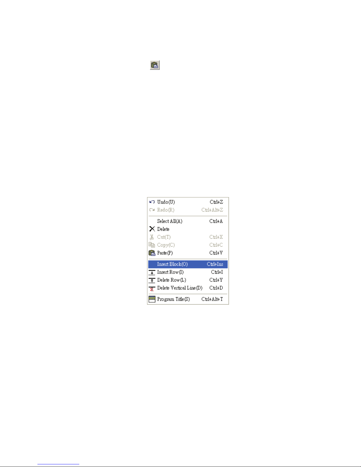
Insert Block(O) Ö Insert a selection (selected block or data) into a program file (This
function is valid for Ladder Diagram Mode only.).
Method 1: Click “Edit(E)” > “Insert Bock(O)”.
Method 2: Use keyboard shortcuts by pressing keys (Ctrl) + (Ins).
Method 3: Right click the mouse to get a pop-up menu and select “Insert Block” in
the pop-up menu.
Insert Row(I) Ö Insert a blank row into a program file.
Method 1: Click “Edit(E)” > “Insert Row(I)”.
Method 2: Use keyboard shortcuts by pressing keys (Ctrl) + (I).
Method 3: Right click the mouse to get a pop-up menu and select “Insert Row” in
the pop-up menu.
Delete Row(L) Ö Delete a row from a program file.
Method 1: Click “Edit(E)” > “Delete Row(L)”.
Method 2: Use keyboard shortcuts by pressing keys (Ctrl) + (Y).
Method 3: Right click the mouse to get a pop-up menu and select “Delete Row” in
the pop-up menu.
Delete Vertical Line(D) Ö Delete the vertical lines from a program file(This function is
valid for Ladder Diagram Mode only.).
Method 1: Click “Edit(E)” > “Delete Vertical Line(D)”.
Method 2: Click the icon
on the toolbar.
Method 3: Use keyboard shortcuts by pressing keys (Ctrl) + (D).
Method 4: Right click the mouse to get a pop-up menu and select “Delete Vertical
Line” in the pop-up menu.
Program Title(S) Ö The information of program title, file name, company name and
designer are shown here and can be printed as an easy cover.
Method 1: Click “Edit(E)” > “Program Title(S)”.
Method 2: Use keyboard shortcuts by pressing keys (Ctrl) + (Alt) + (T).
Page 15

Chapter 2 HMI-WPLSoft Introduction|DOP-EXIO Series
2-8
Revision March, 2008, Doc. Name: 2007PDD23000014
2.3 Compiler
The “Compiler” function is shown as follows, including pull-down menu options:
Ladder => Instruction(I) Ö Convert ladder diagrams to instruction codes.
Method 1: Click “Compiler(P)” > “Ladder => Instruction(I)”.
Method 2: Click the icon on the toolbar.
Method 3: Use keyboard shortcuts by pressing keys (Ctrl) + (F9).
Instruction => Ladder(L) Ö Convert instruction codes to ladder diagrams.
Method 1: Click “Compiler(P)” > “Instruction => Ladder(L)”.
Method 2: Click the icon
on the toolbar.
Method 3: Use keyboard shortcuts by pressing keys (Ctrl) + (F10).
2.4 Comments
The “Comments” function is shown as follows, including pull-down menu options:
Page 16

Chapter 2 HMI-WPLSoft Introduction|DOP-EXIO Series
Revision March, 2008, Doc. Name: 2007PDD23000014 2-9
Edit Device Comments(D) Ö Insert a comment for every operand of the device
where the cursor is positioned.
Method 1: Click “Comment(M)” > ” Edit Device Comments(D)”.
Method 2: Use keyboard shortcuts by pressing keys (Ctrl) + (Alt) + (D).
Method 3: Right click the mouse to get a pop-up menu and select “Edit Device
comments” in the pop-up menu.
Edit Segment Comments(B) Ö Insert a segment comment in the blank row (This
function is valid for Ladder Diagram Mode only.).
Method 1: Click “Comment(M)” > "Edit Segment Comments(B)”.
Method 2: Use keyboard shortcuts by pressing keys (Ctrl) + (Alt) + (B).
Method 3: Right click the mouse to get a pop-up menu and select “Edit Segment
Comments” in the pop-up menu.
Edit Row Comments(L) Ö Insert a row comment after output coil or instruction of
each row (This function is valid for Ladder Diagram Mode only.).
Method 1: Click “Comment(M)” > ” Edit Row Comments(L)”.
Method 2: Use keyboard shortcuts by pressing keys (Ctrl) + (Alt) + (L).
Method 3: Right click the mouse to get a pop-up menu and select “Edit Row
comments” in the pop-up menu.
2.5 Search
The “Search” function is shown as follows, including pull-down menu options:
Page 17

Chapter 2 HMI-WPLSoft Introduction|DOP-EXIO Series
2-10
Revision March, 2008, Doc. Name: 2007PDD23000014
Go to(J) Ö Jump to the designated location (unit: Step).
Method 1: Click “Search(S)” > ”Go to(J)”.
Method 2: Click the icon on the toolbar.
Method 3: Use keyboard shortcuts by pressing keys (Ctrl) + (J).
Search/Replace(F) Ö Search or replace the device name and instruction of the
designated device.
Method 1: Click “Search(S)” > ”Search/Replace(F)”.
Method 2: Click the icon on the toolbar.
Method 3: Use keyboard shortcuts by pressing keys (Ctrl) + (F).
Go to the Start(T) Ö Jump to the start of the program.
Method 1: Click “Search(S)” > ”Go to the Start(T)”.
Method 2: Use keyboard shortcuts by pressing keys (Ctrl) + (Home).
Go to the End(N) Ö Jump to the end of the program.
Method 1: Click “Search(S)” > ”Go to the End(N)”.
Method 2: Use keyboard shortcuts by pressing keys (Ctrl) + (End).
2.6 View
The “View” function is shown as follows, including pull-down menu options:
Page 18

Chapter 2 HMI-WPLSoft Introduction|DOP-EXIO Series
Revision March, 2008, Doc. Name: 2007PDD23000014 2-11
Toolbars(T) Ö Display a list of the toolbars available in HMI-WPLSoft, including
Status Bar, Standard, PLC and Ladder Diagram toolbars.
~ Status Bar: display or hide status bar.
Method: Click “View(V)” > “Toolbars(T)” > “Status Bar”.
~ Standard: display or hide standard toolbar.
Method: Click “View(V)” > “Toolbars(T)” > “Standard”.
~ PLC: display or hide HMI-WPLSoft toolbar.
Method: Click “View(V)” > “Toolbars(T)” > “PLC”.
~ Ladder Diagram toolbar: display or hide Ladder Diagram toolbar (display in
Ladder Diagram Mode only).
Method: Click “View(V)” > “Toolbars(T)” > “Ladder Diagram”.
Zoom(Z) Ö Let the user change and reduce the magnification level of the program.
Zoom In function is used to get a closer look of the program and Zoom Out
function is used to see more of the program. The default settings for zooming
provided by the system are Auto, 50 %, 75 %, 100 %, 125 %, 150 %, 175 % and
200 %.
Method 1: Click “View(V)” > “Zoom (Z)”.
Method 2: Zoom In. Use keyboard shortcuts by pressing keys (Shift) + (Alt) + (I)
or click the icon on the toolbar to zoom in.
Method 3: Zoom Out. Use keyboard shortcuts by pressing keys (Shift) + (Alt) +
(O) or click the icon on the toolbar to zoom out.
Page 19

Chapter 2 HMI-WPLSoft Introduction|DOP-EXIO Series
2-12
Revision March, 2008, Doc. Name: 2007PDD23000014
Instruction List(I) Ö Change to Instruction Mode.
Method 1: Click “View(V)” > “Instruction List(I)”.
Method 2: Click the icon on the toolbar.
Ladder Diagram(L) Ö Change to Ladder Diagram Mode.
Method 1: Click “View(V)” > “Ladder Diagram(L)”.
Click the icon on the toolbar.
List of Used Device(U) Ö Display all device usage status.
Method 1: Click “View(V)” > “List of Used Device(U)”.
Method 2: Use keyboard shortcuts by pressing keys (Ctrl)+ (Alt) + (U).
Show Comments(M) Ö Display or hide device comments.
Method 1: Click “View(V)” > “Show Comments(M)”.
Method 2: Click the icon on the toolbar.
2.7 Options
The “Options” function is shown as follows, including pull-down menu options:
Prompt to Edit Device Comment(H) Ö If this option is selected, in Instruction Mode
or Ladder Diagram Mode, the system will ask the user to enter the corresponding
device comment at the same time when the user uses the instruction code to edit a
DOP-EXIO series program.
Method: Click “Options(O)” > “Prompt to Edit Device Comment(H)”.
Page 20

Chapter 2 HMI-WPLSoft Introduction|DOP-EXIO Series
Revision March, 2008, Doc. Name: 2007PDD23000014 2-13
Language Setup(L) Ö Allow the user to change the display language of
HMI-WPLSoft by requirement. There are three available languages for selection,
Tranditional Chinese, Simplied Chinese and English.
Method: Click “Options(O)” > “Language Setup(L)”.
2.8 Window
The “Window” function is shown as follows, including pull-down menu options:
Cascade(C) Ö Arrange windows in an overlapping way.
Method: Click “Window(W)” > “Cascade(C)”.
Title Horizontally(H) Ö Arrange the file in a horizontal way.
Method: Click “Window(W)” > “Title Horizontally(H)”.
Title Vertically(V) Ö Arrange files in a vertical way.
Method: Click “Window(W)” > “Title Vertically(V)”.
The current files list Ö e.g. Instruction Mode and Ladder Diagram Mode.
Method: In HMI-WPLSoft editing window, activate Instruction Mode and Ladder
Diagram Mode and click “Window(W)”, and then the user can see
them show in Window drop-down menu.
Page 21

Chapter 2 HMI-WPLSoft Introduction|DOP-EXIO Series
2-14
Revision March, 2008, Doc. Name: 2007PDD23000014
2.9 Help
The “Help” function is shown as follows, including pull-down menu options:
About HMI-WPLSoft(A) Ö This command shows the version information of
HMI-WPLSoft.
Method: Click “Help(H)” > “About HMI-WPLSoft(A)”.
Page 22

Chapter 3 Creating and Editing Programs|DOP-EXIO Series
Revision March, 2008, Doc. Name: 2007PDD23000014 3-1
Chapter 3 Creating and Editing Programs
Activate HMI-WPLSoft, and then the system will enter into Ladder Diagram Mode as shown as
the Fig. 3.1 below.
Fig. 3.1 Ladder Diagram Mode
There is a ladder diagram toolbar shown on the top of the Ladder Diagram Mode window. To
create and edit a ladder diagram, the user can click the icon on toolbar directly by the mouse
or move the editing block to the proper position and enter instructions. Besides, the user also
can press F1 ~ F12 function keys on the keyboard to create and edit the ladder diagram.
Please refer to the following sections for how to create and edit ladder diagram.
3.1 Basic Operation
Example: Create the diagram shown below.
Using the mouse and F1 ~ F12 function keys on the keyboard.
Menu Bar
Toolbar
Ladder Diagram
Editing Area
Instruction
Editing Area
Status Bar
Page 23

Chapter 3 Creating and Editing Programs|DOP-EXIO Series
3-2
Revision March, 2008, Doc. Name: 2007PDD23000014
1. Click the Normally Open Contact icon on the toolbar or press F1 function key.
2. The “Device Input” dialog box will appear. The user can select device name (e.g. M) ,
device number (e.g. 10), and enter comments (e.g. Internal Relay). Then, press the
button “OK” to save the settings.
3. Click the Output Coil icon on the toolbar or press F7 function key. The “Device
Input” dialog box will appear next. The user can select device name (e.g. Y), device
number (e.g. 0), and enter comments (e.g. Output Relay). Then, press the button
“OK” to save the settings.
Page 24

Chapter 3 Creating and Editing Programs|DOP-EXIO Series
Revision March, 2008, Doc. Name: 2007PDD23000014 3-3
4. Click Application Instruction icon or press F6 function key. Choose “Function”
from the “Function” drop-down menu and select “END” instruction from the
“Application Instruction” drop-down menu. The user can also type in “END” instruction
directly in the field of "Application Instruction". Then, press the button “OK” to save
the settings.
Page 25

Chapter 3 Creating and Editing Programs|DOP-EXIO Series
3-4
Revision March, 2008, Doc. Name: 2007PDD23000014
5. Click the icon to compile the ladder diagram and convert it to instruction codes.
After compiler action is completed, the numbers of steps will show on the left-hand
side of the start of the ladder diagram.
6. If the ladder diagram is not correct, an error message dialog box will appear and point
out the exact erroneous rows and addresses after the compiler action is completed.
Page 26

Chapter 3 Creating and Editing Programs|DOP-EXIO Series
Revision March, 2008, Doc. Name: 2007PDD23000014 3-5
Keyboard Operation
1. Place the editing block at the start of the program (Row: 0, Col: 1), and type in “LD
M10” by using the keyboard. Then, press the Enter key on the keyboard, or click the
“OK” button to complete the settings.
2. Type in “OUT Y0” by using the keyboard and press Enter key on the keyboard. Then,
type in “END” by using the keyboard and press Enter key on the keyboard. Finally,
click the icon to compile the completed ladder diagram.
If the user wants to edit the comments at the same time when input an instruction by
using keyboard, the user can click the “Prompt to Edit Device Comment(H)” under the
“Options” menu. Then, the “Comment” dialog box (see the figure below) will appear for
the user to enter and edit the corresponding comments after an instruction is input
correctly.
Page 27

Chapter 3 Creating and Editing Programs|DOP-EXIO Series
3-6
Revision March, 2008, Doc. Name: 2007PDD23000014
3.2 Editing Example
Ladder Diagram
Operation steps for editing the Ladder Diagram
Step
Ladder
Symbol
Cursor
Location
Input by clicking the Icon on the
toolbar
Input by using the
Keyboard
1
Row: 0,
Column: 1 *Footnote 1
Device Name: X
Device Number: 1
LD X1 ↵ or A X1 ↵
2
Row: 0,
Column:2 *Footnote 2
Device Name: Y
Device Number:0
OUT Y0↵ or O Y0
3
Row: 1,
Column: 1
Device Name: X
Device Number:2
LD X2 ↵ or A X2 ↵
4
Row: 1,
Column: 2
F9
5
Row: 1,
Column: 2
Device Name: Y
Device Number:2
OUT Y2 ↵ or O Y2 ↵
6
Row: 2,
Column: 1
Device Name: X
Device Number:1
LD X1 ↵ or A X1 ↵
7
Row: 3,
Column: 1
Device Name: M
Device Number:0
LD M0 ↵ or A M0 ↵
8
Row: 3,
Column: 2 *Footnote 3
MOV Instruction
Operand 1: D Device
Number:1
Operand 2: D Device
Number:2
MOV D1 D2 ↵
9
Row: 4,
Column: 0
Double click the
mouse and enter P0
P0 ↵
Page 28

Chapter 3 Creating and Editing Programs|DOP-EXIO Series
Revision March, 2008, Doc. Name: 2007PDD23000014 3-7
Step
Ladder
Symbol
Cursor
Location
Input by clicking the Icon on the
toolbar
Input by using the
Keyboard
10
Row: 4,
Column: 1
Device Name: M
Device Number:1
LDP M1 ↵ or + M1 ↵
11
Row: 4,
Column: 2
F9
12
Row: 4,
Column: 2
CNT Instruction
Operand 1: C Device
Number: 0
Operand 2: K Device
Number: 100
CNT C0 K100 ↵
13
Row: 5,
Column: 1
Device Name: M
Device Number: 1
LDF M1 ↵ or – M1 ↵
14
Row: 6,
Column: 1
END Instruction
END ↵
After the ladder diagram is completed, the user can compile and convert the completed
ladder diagram to instruction codes. The ladder diagram which has been converted to
instruction codes is shown as the figure below.
Page 29

Chapter 3 Creating and Editing Programs|DOP-EXIO Series
3-8
Revision March, 2008, Doc. Name: 2007PDD23000014
*Footnote 1: Input Basic Instruction
1. Click the icon on the toolbar or press the F1 function key on the keyboard
and the “Device input” dialog box will appear. Then, the user can enter device
name, device number, and edit comments in this dialog box.
2. For example, select the device name “X” and device number “1” from the
drop-down menu or type in the device name “X” and device number “1” by using
the keyboard. Then, press Enter key on the keyboard or click the “OK” button to
save the settings.
*Footnote 2: Input Output Coil
1. Click the icon on the toolbar or press the F7 function key on the keyboard
and the “Device input” dialog box will appear. Then, the user can enter device
name, device number, and edit comments in this dialog box.
Page 30

Chapter 3 Creating and Editing Programs|DOP-EXIO Series
Revision March, 2008, Doc. Name: 2007PDD23000014 3-9
2. For example, select the device name “Y” and device number “1” from the
drop-down menu or type in the device name “Y” and device number “1” by using
the keyboard. Then, press Enter key on the keyboard or click the “OK” button to
save the settings.
*Footnote 3: Input Application Instruction
1. Click the icon on the toolbar or press the F6 function key on the keyboard
and the “Application Instructions” dialog box will appear.
2. First, choose one selection from the “Function List” drop-down menu (including
all application instructions and output commands, etc.). Then, select the “API
Number” and “Application Instruction”. The user can also type in the desired
instruction, e.g. MOV in the "Application Instruction" drop-down menu directly.
After all settings are completed, press Enter key on the keyboard.
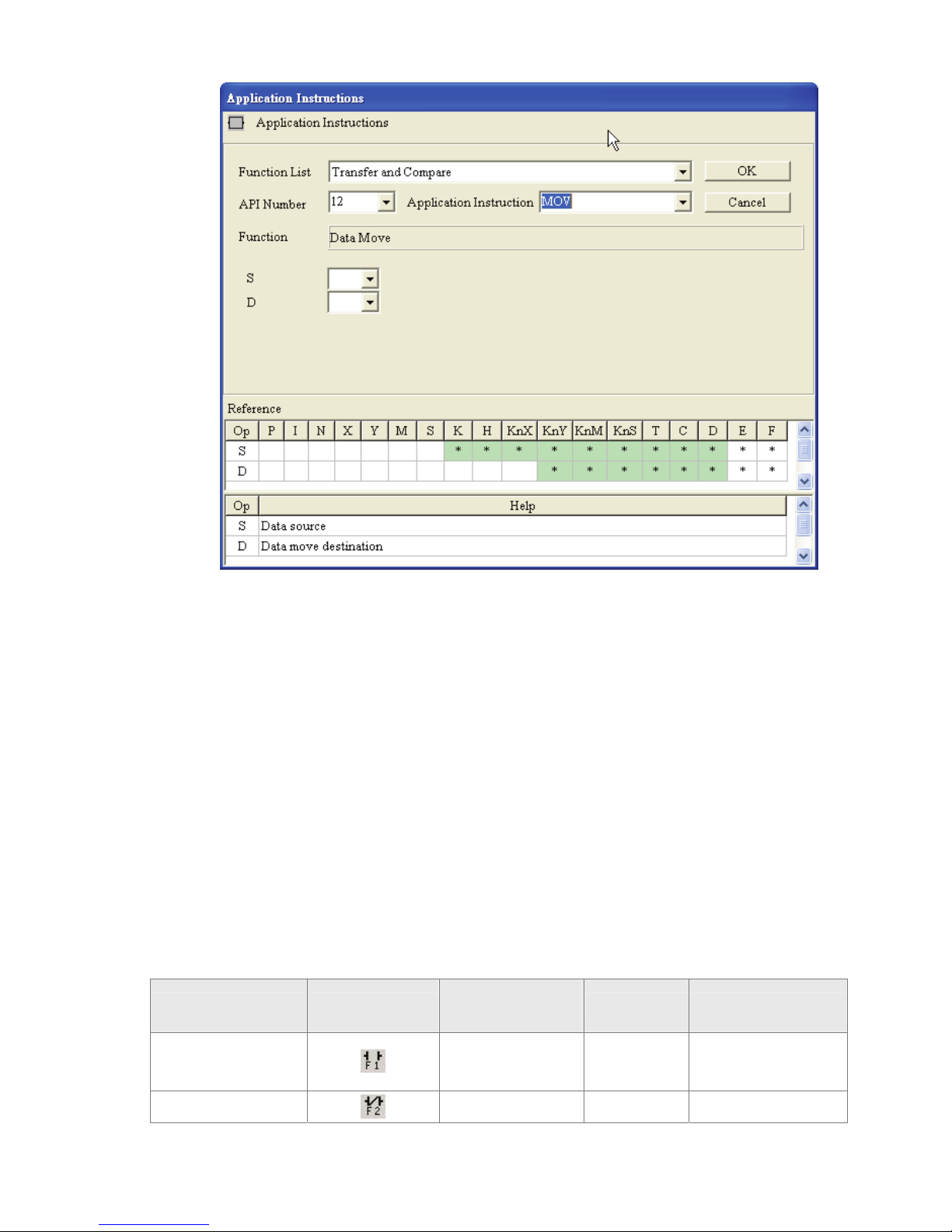
3. Select “Transfer and Compare” from the “Function List” drop-down menu and
type in “MOV” in the field of "Application Instruction" directly (or choose “MOV”
instruction from the “Application Instruction” drop-down menu). Then, press Enter
key on the keyboard, and the user can see the figure below on the screen.
Page 31
Chapter 3 Creating and Editing Programs|DOP-EXIO Series
3-10
Revision March, 2008, Doc. Name: 2007PDD23000014
4. Input device name in the field of “S” (Operand 1) and “D” (Operand 2), and input
device number in the field of “Device Number” in order. Select index register E or
F if it exists. Then, press the “OK” button to save the settings.
5. The user can also double click the mouse on the “@” or “*” symbol in the device
reference table (refer to the figure above) to designate the device name (The
symbol @ indicates this device can be modified by index register E or F and the
symbol * indicates this device can not be modified by index register E or F).
3.3 Ladder Diagram Editing Explanation
)
Keyboard Entry
HMI-WPLSoft provides several brevity codes for the user to input Instructions more quickly
and conveniently when editing a ladder diagram. Please refer to the following table.
Explanation Instruction Icon
Instruction Code
(Mnemonic Code)
Brevity Code Example
Normally open
contact
LD A LD M0 or A M0
Normally closed
LDI B LDI M0 or B M0
Page 32

Chapter 3 Creating and Editing Programs|DOP-EXIO Series
Revision March, 2008, Doc. Name: 2007PDD23000014 3-11
Explanation Instruction Icon
Instruction Code
(Mnemonic Code)
Brevity Code Example
contact
Rising pulse
LDP + LDP M0 or + M0
Falling pulse
LDF – LDF M0 or – M0
Output coil
OUT O OUT M0 or O M0
) Insert / Replace Mode
Using the “Insert” key on the keyboard can switch to the Insert Mode or the Replace Mode
when editing a ladder diagram.
If the “Replace” word is displayed on the status bar, pressing the Insert key on the
keyboard is to switch to the Insert Mode. In the Insert Mode, insert a new ladder
diagram to where the editing block is located, and the original ladder diagrams
following the new diagram will shift one space to the right.
If the “Insert” word is displayed on the status bar, pressing the Insert key on the
keyboard is to switch to the Replace Mode. In Replace Mode, inserting a new ladder
diagram can replace the original ladder diagram located in the editing block, and the
following other ladder diagrams will not be changed.
) Edit(E)
Undo(U) Ö Undo the most recent actions (the system allows the user to perform undo
action for max. 10 times)
Method 1: Click “Edit(E)” > “Undo(U)”.
Method 2: Click the icon on the toolbar.
Method 3: Use keyboard shortcuts by pressing keys (Ctrl) + (Z).
Method 4: Right click the mouse to get a pop-up menu and select “Undo” in the
pop-up menu.
Redo(R) Ö Redo the undo action.
Method 1: Click “Edit(E)” > “Redo(R)”.
Method 2: Click the icon on the toolbar.
Method 3: Use keyboard shortcuts by pressing keys (Ctrl) + (Alt) + (Z).
Method 4: Right click the mouse to get a pop-up menu and select “Redo” in the
pop-up menu.
Page 33
Chapter 3 Creating and Editing Programs|DOP-EXIO Series
3-12
Revision March, 2008, Doc. Name: 2007PDD23000014
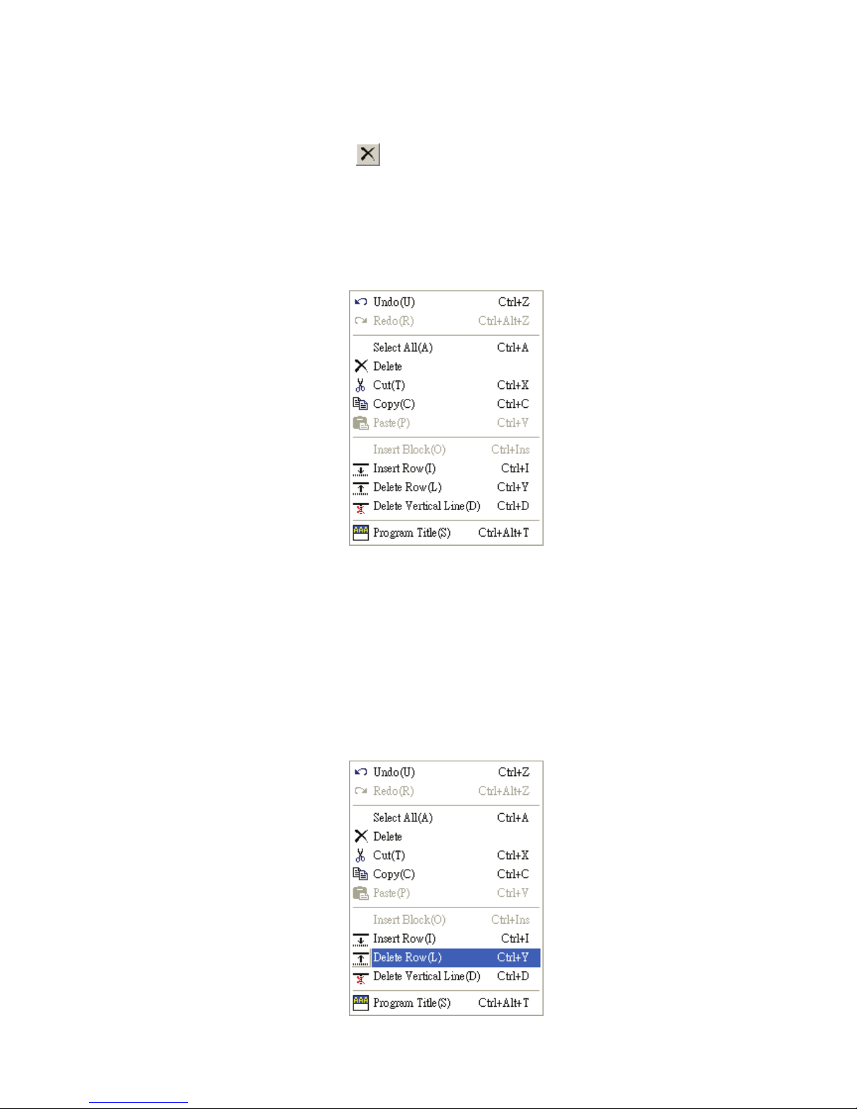
Delete Ö Delete a selection (selected block or data) where the cursor is.
Method 1: Click “Edit(E)” > “Delete”.
Method 2: Click the icon on the toolbar.
Method 3: Use keyboard shortcuts by pressing key (Delete).
Method 4: Move the cursor to the diagram block that the user wants to delete and
right click the mouse to get a pop-up menu and select “Delete” in the
pop-up menu to delete the selected diagram block.
Delete Row(L) Ö Delete a row or several rows in the ladder diagram
Method 1: Click “Edit(E)” > “Delete Row(L)”. Then, the row where the cursor is will
be deleted and the rows below the deleted row will move up.
Method 2: Use keyboard shortcuts by pressing keys (Ctrl) + (Y).
Method 3: Move the cursor to the row that the user wants to delete and right click
the mouse to get a pop-up menu and select “Delete Row(L)” in the
pop-up menu to delete the row.
Page 34
Chapter 3 Creating and Editing Programs|DOP-EXIO Series
Revision March, 2008, Doc. Name: 2007PDD23000014 3-13
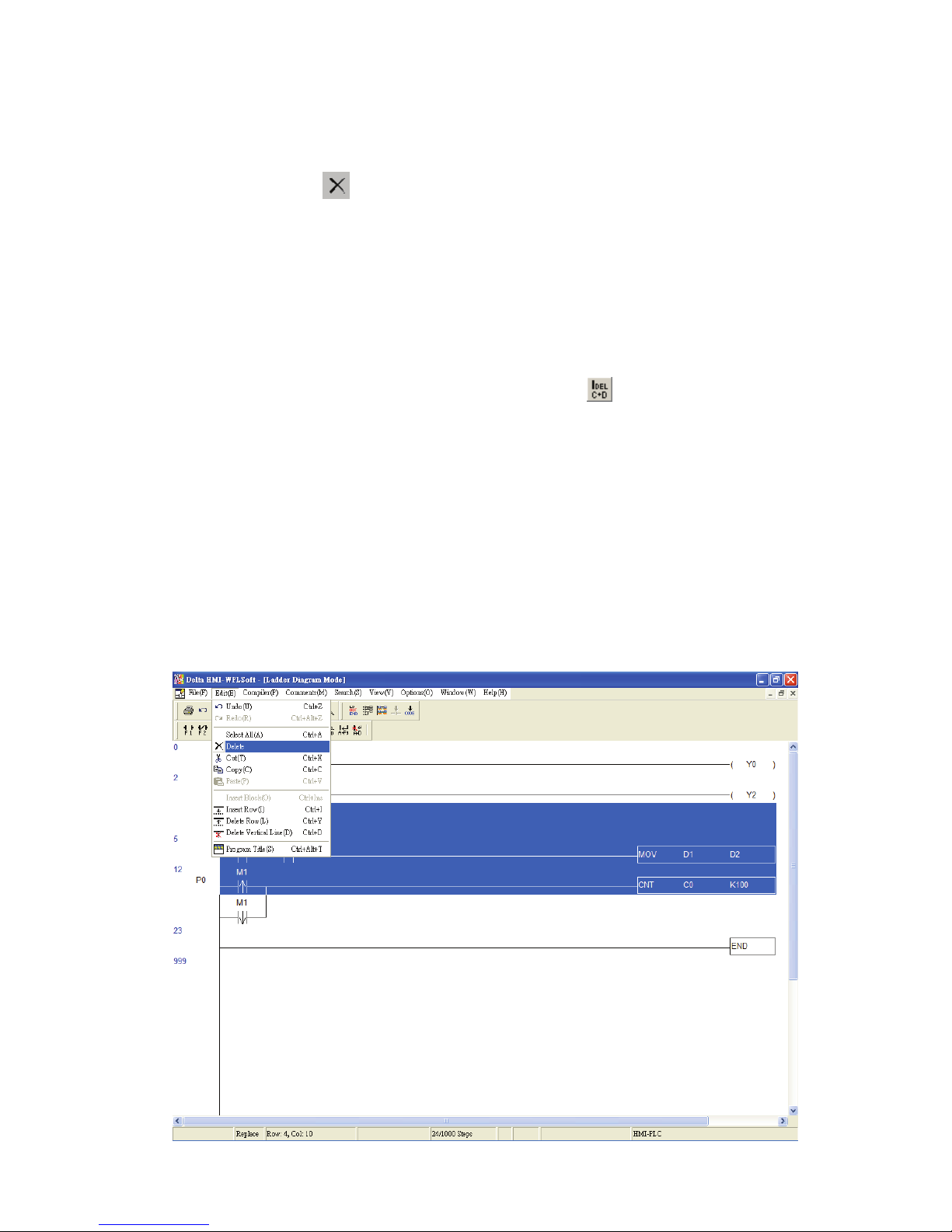
Method 4: Select the row that the user wants to delete. Right clicking the mouse to
select the “Delete” command in the pop-up menu can delete the selected
row immediately. Pressing the Delete key on the keyboard or clicking the
icon on the toolbar can also delete the selected row.
Delete Vertical Line(D) Ö Delete the vertical lines in the ladder diagram.
Method 1: Click “Edit(E)” > “Delete Vertical Line(D)”. Then, the vertical line on the
left-hand side of the editing block will be deleted.
Method 2: Use keyboard shortcuts by pressing keys (Ctrl) + (D).
Method 3: Move the editing block to the right-hand side of the vertical line that the
user wants to delete and click the icon on the toolbar. Then, the
vertical line on the left-hand side of the editing block will be deleted.
Method 4: Move the editing block to the right-hand side of the vertical line that the
user wants to delete. Right click the mouse to get a pop-up menu and
select “Delete Vertical Line(D)” in the pop-up menu. Then, the vertical
line on the left-hand side of the editing block will be deleted.
Delete Block Ö Delete the selected block.
Method 1: Click “Edit(E)” > “Delete”. Then, the selected block in the ladder diagram
that the user wants to delete will be deleted immediately.
Page 35
Chapter 3 Creating and Editing Programs|DOP-EXIO Series
3-14
Revision March, 2008, Doc. Name: 2007PDD23000014
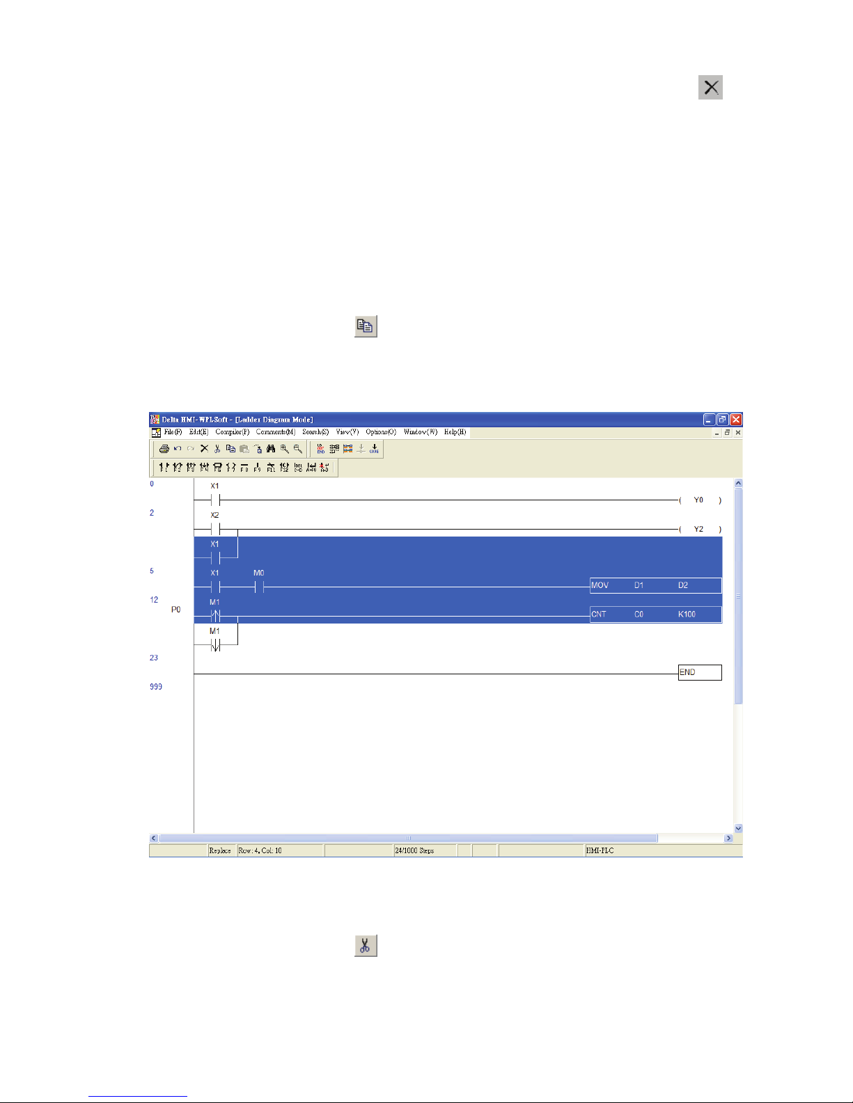
Method 2: Select the block that the user wants to delete and click the icon on
the toolbar.
Method 3: Select the block that the user wants to delete and right click the mouse to
select the “Delete” command in the pop-up menu.
Method 4: Select the block that the user wants to delete and press the Delete key
on the keyboard.
Copy Block Ö Copy the selected block.
Method 1: Click “Edit(E)” > “Copy(C)”.
Method 2: Click the icon on the toolbar.
Method 3: Use keyboard shortcuts by pressing keys (Ctrl) + (C).
Method 4: Right click the mouse to select the “Copy” command in the pop-up menu.
Cut Block Ö Cut the selected block.
Method 1: Click “Edit(E)” > “Cut(T)”.
Method 2: Click the icon on the toolbar.
Method 3: Use keyboard shortcuts by pressing keys (Ctrl) + (X).
Method 4: Right click the mouse to select the “Cut” command in the pop-up menu.
Page 36
Chapter 3 Creating and Editing Programs|DOP-EXIO Series
Revision March, 2008, Doc. Name: 2007PDD23000014 3-15
Paste Block Ö Paste the selected block.
Method 1: Click “Edit(E)” > “Paste(P)”.
Method 2: Click the icon on the toolbar.
Method 3: Use keyboard shortcuts by pressing keys (Ctrl) + (V).
Method 4: Right click the mouse to select the “Paste” command in the pop-up
menu.
Insert Block Ö Insert the selected block (This function is valid after the “Copy Block”
function is executed. Therefore, before inserting the selected block, perform “Copy
Block” action first).
Method 1: Click “Edit(E)” > “Insert Block(O)”.
Method 2: Use keyboard shortcuts by pressing keys (Ctrl) + (Ins).
Method 3: Right click the mouse to select the “Insert Block” command in the pop-up
menu.
) Compiler(P)
This function is used to compile current HMI-WPLSoft programs for DOP-EXIO series
product. If the user completes the editing of the ladder diagram in the ladder diagram mode,
performing this function will check whether the ladder diagram is valid or not. If there is no
error occurred when converting the program, the ladder diagram can be converted to the
instruction program successfully; meanwhile, the program memory addresses (numbers of
steps) for each editing block will appear on the left-hand side of the start of the ladder
diagram. However, if there is any error occurred, a ladder diagram error message dialog
box will appear to display the error code and point out the exact erroneous addresses
(exact row and column where the error occurred) after the compiler action is completed.
If the user completes program editing in the instruction mode when performing this function,
the system will start to check if there is any error occurred or not. If there is no error, the
Page 37
Chapter 3 Creating and Editing Programs|DOP-EXIO Series
3-16
Revision March, 2008, Doc. Name: 2007PDD23000014
instruction program will be converted to the ladder diagram successfully. However, if there
is any error occurred, an error message dialog box will appear to display the error code
and point out the exact erroneous steps (where the error occurred) after the compiler
action is completed.
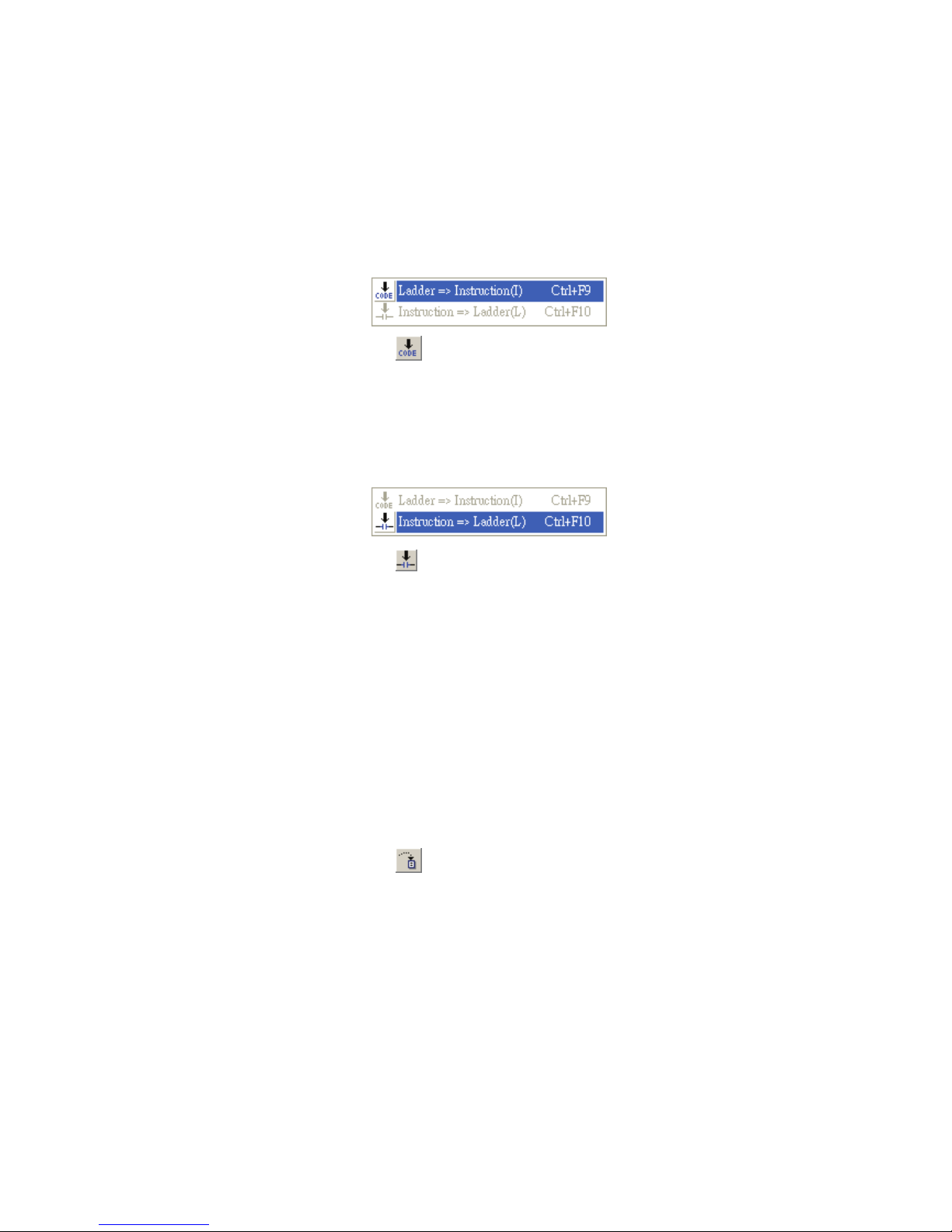
Ladder => Instruction(I) Ö This function is valid in Ladder Diagram Mode only.
Method 1: Click “Compiler(P)” > “Ladder => Instruction(I)”.
Method 2: Click the icon on the toolbar.
Method 3: Use keyboard shortcuts by pressing keys (Ctrl) + (F9).
Instruction => Ladder(L) Ö This function is valid in Instruction Mode only.
Method 1: Click “Compiler(P)” > “Instruction => Ladder(L)”.
Method 2: Click the icon on the toolbar.
Method 3: Use keyboard shortcuts by pressing keys (Ctrl) + (F10).
) Search(S)
Go to(J) Ö Jump to the designated location (unit: Step). This command is used to
specify the program to jump to a designated location. If the designated step already
exists, the program will jump to this existing designated step and put it in the first line.
Method 1: Click “Search(S)” > ”Go to(J)”. Enter the designated step where the user
want to jump to, and then the ladder diagram will put this designated step
in the first line.
Method 2: Click the icon on the toolbar.
Method 3: Use keyboard shortcuts by pressing keys (Ctrl) + (J).
Search/Replace(F)
The “Search/Replace(F)” command is used to search and replace the device and
instruction within the program (if only the “Search” command is used, just enter the
device name to be searched in the dialog box). If the device or the command is found,
the view will be scrolled to the device or the command. Also, the user can search and
replace the device and instruction by specifying the type of the device and instruction.
Method 1: Click “Search(S)” > ”Search/Replace(F)”.
Page 38
Chapter 3 Creating and Editing Programs|DOP-EXIO Series
Revision March, 2008, Doc. Name: 2007PDD23000014 3-17
Method 2: Click the icon on the toolbar.
Method 3: Use keyboard shortcuts by pressing keys (Ctrl) + (F).
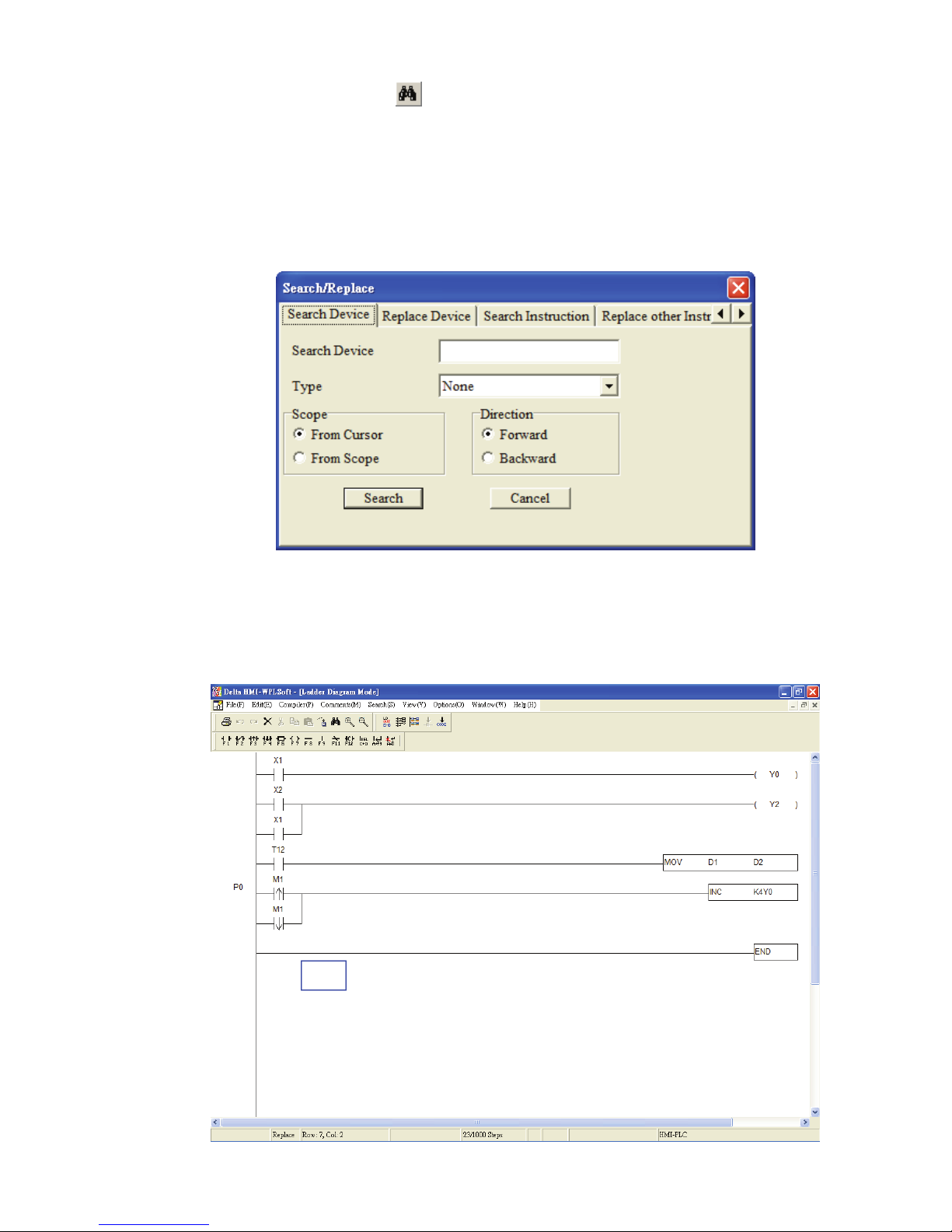
When the user selects the “Search/Replace” command, the following “Search/Replace”
dialog box will appear. There are “Search Device”, “Replace Device”, “Search
Instruction” and “Replace other Instruction” four functions in this dialog box for the user
to use.
Search Device
Use this command to search the specified device name match the search criteria in the
program. For example, in the ladder diagram shown below, the instructions that contain
device name Y0 are OUT Y0 and INC K4Y0.
Page 39
Chapter 3 Creating and Editing Programs|DOP-EXIO Series
3-18
Revision March, 2008, Doc. Name: 2007PDD23000014
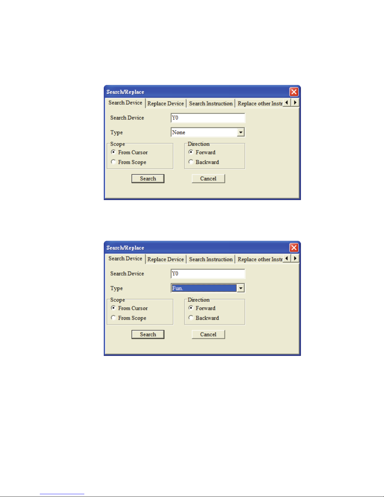
Activate “Search/Replace” fuction to open “Search/Replace” dialog box and choose the
“Search Device” tab. Enter device name “Y0” in the field of “Search Device” and select
the “None” in the field of “Type”. Then, press the “Search” button and the system will
find the instructions “OUT Y0” and “INC K4Y0”.
However, if enter the device name “Y0” in the field of “Search Device” still, but change
the “None” to “Fun.” in the field of “Type”, only the instruction “INC K4Y0” will be found
when “Search” button is pressed.
Replace Device
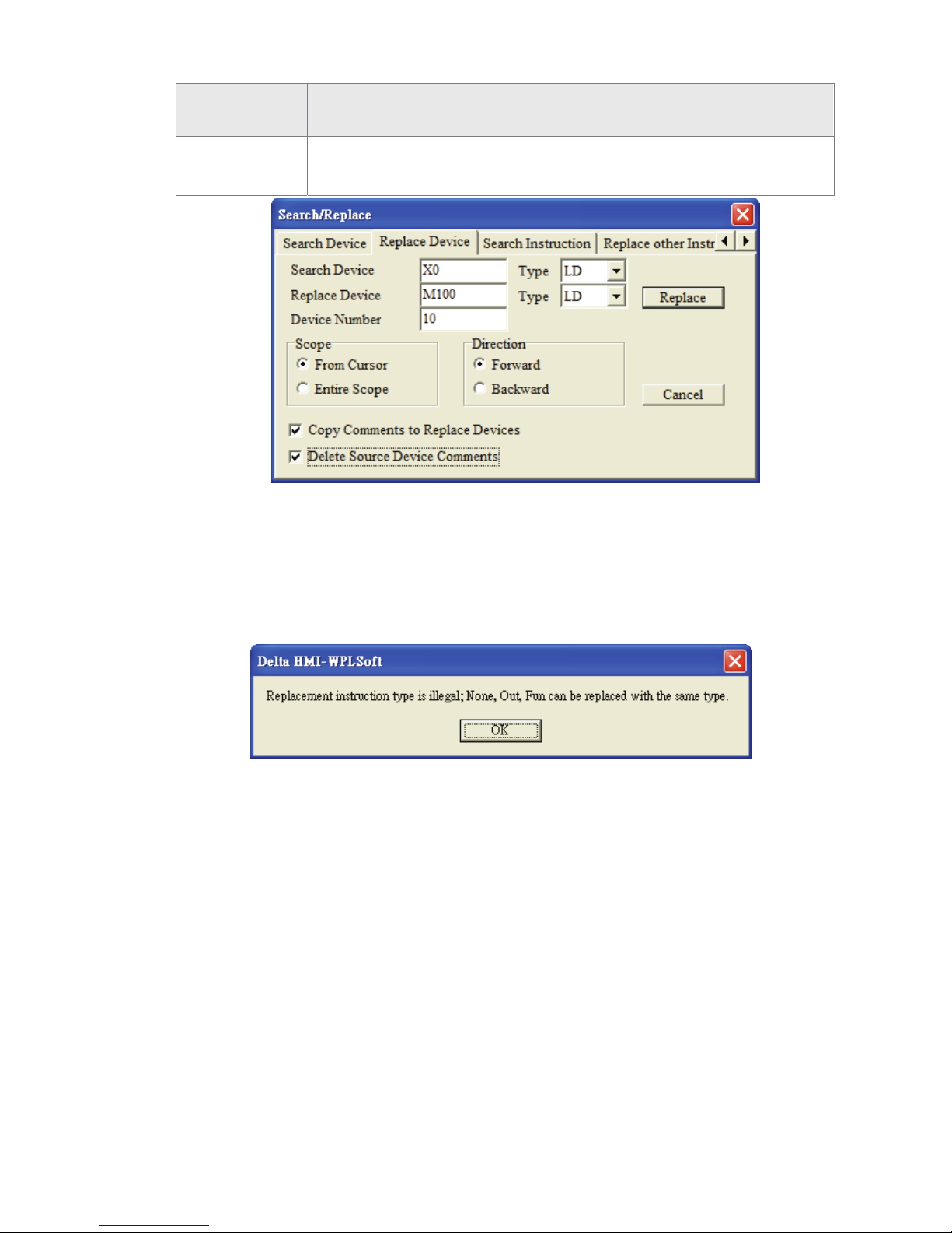
Use this command to replace the specified device name match the search criteria in the
program. For example, activate “Search/Replace” fuction and choose the “Replace
Device” tab. In “Replace Device” tab, enter the “X0” in the field of “Search Device” and
select the type of search device as “LD”. Then, enter the “M100” in the field of “Replace
Device” and select the type of replace device as “LD”. Next, type in “10” in the field of
“Device Number”. Finally, press the “Replace” button, and the instructions which match
the criteria will be changed to LD M100~M109.
Page 40
Chapter 3 Creating and Editing Programs|DOP-EXIO Series
Revision March, 2008, Doc. Name: 2007PDD23000014 3-19
Original
Command
Criteria
Replaced
Command
LD X0~X7
LD X10~X11
Type LD + Device X0 → Type LD + Device M100
Device Number: 10
LD M100~M107
LD M108~M109
If the user choose the device type as None, Out and Fun these three types, only the
same type of the device which the name match the replace criteria can be replaced.
When None, Out and Fun these three types are selected, if the user tries to replace the
different type of the device, a warning message dialog box looks like the figure below
will appear.
Besides, the user can use “Copy Comments to Replace Devices” this option to copy the
comments into the replace device. If “Delete Source Device Comments” this option is
also selected, the comments of the search device will be deleted after the comments of
the search device has been copied to the replace device. In this case, the boxes next to
“Copy Comments to Replace Devices” and “Delete Source Device Comments” are
checked both. It indicates that when the device name is replaced, i.e. the “Replace”
button is pressed, the comment of the search device “X0” will be copied to the replace
device “M100” and the comment of the search device “X0” will be deleted immediately
at the same time.
Limits
In “Replace Device” dialog box, only the devices of the same type can be replaced. For
example, if D1 is replaced by D11, it is thus viewed as successful replacement; but if it
Page 41
Chapter 3 Creating and Editing Programs|DOP-EXIO Series
3-20
Revision March, 2008, Doc. Name: 2007PDD23000014
is replaced by C100, it is then a failure.
Search Instruction
Use this command to search the specified instruction name match the search criteria in
the program. Click “Search Instruction” tab after the “Seach/Replace” function is
activated, and enter the instruction name that the user is looking for in the field of
“Search Instruction”. Then, press the “Search” button to start the search. The system
will memorize and record all the searched instruction names in the “Search Instruction”
drop-down menu. This is a useful function for the user to search more quickly and
conveniently next time.
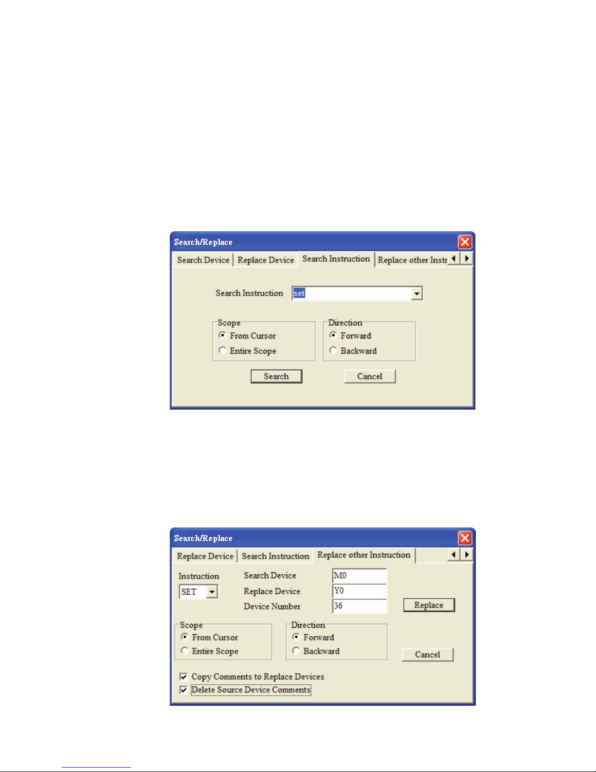
Replace other Instruction
In “Replace other Instruction” tab, the system provides the replace criteria for SET, RST,
PLS and PLF, these four kinds of instructions and allows the user to replace the devices
match the criteria of these instructions in the program. For example, if the user wants to
replace SET M0 ~ M35 with SET Y0 ~ Y43, in order to complete the replacement, the
user can set the settings as shown as the figure below.
Page 42

Chapter 3 Creating and Editing Programs|DOP-EXIO Series
Revision March, 2008, Doc. Name: 2007PDD23000014 3-21
Besides, as the boxes next to “Copy Comments to Replace Devices” and “Delete
Source Device Comments” are checked both, it indicates that when the device name is
replaced, the comments of the search device “M0 ~ M35” will be copied to the replace
device “Y0 ~ Y43” and the comments of the search device “M0 ~ M35” will be deleted
immediately at the same time.
Go to the Start(T) Ö Jump to the start of the program.
Method 1: Click “Search(S)” > ”Go to the Start(T)”.
Method 2: Use keyboard shortcuts by pressing keys (Ctrl) + (Home).
Go to the End(N) Ö Jump to the end of the program.
Method 1: Click “Search(S)” > ”Go to the End(N)”.
Method 2: Use keyboard shortcuts by pressing keys (Ctrl) + (End).
3.4 Editng Instructions
Input DOP-EXIO Series Instructions
After entering the instruction mode, the user may type an instruction directly. If the
instruction format is valid, press the Enter key on the keyboard to complete the settings.
The input instructions will be located in the editing area and the program memory
address of DOP-EXIO series will appear on the left-hand side of the program. Thus, the
user can get the corresponding program memory addresses of the instructions clearly.
For the introductions of the formats of all instructions, please refer to Appendix A and
Appendix B in this manual.
3.5 Editing Comments
In the ladder diagram mode, there are three operating modes for editing comments: Device
comments, Segment comments and Row comments. Please refer to the following sections for
more introductions on editing comments.
Ladder Diagram Mode:
Page 43
Chapter 3 Creating and Editing Programs|DOP-EXIO Series
3-22
Revision March, 2008, Doc. Name: 2007PDD23000014
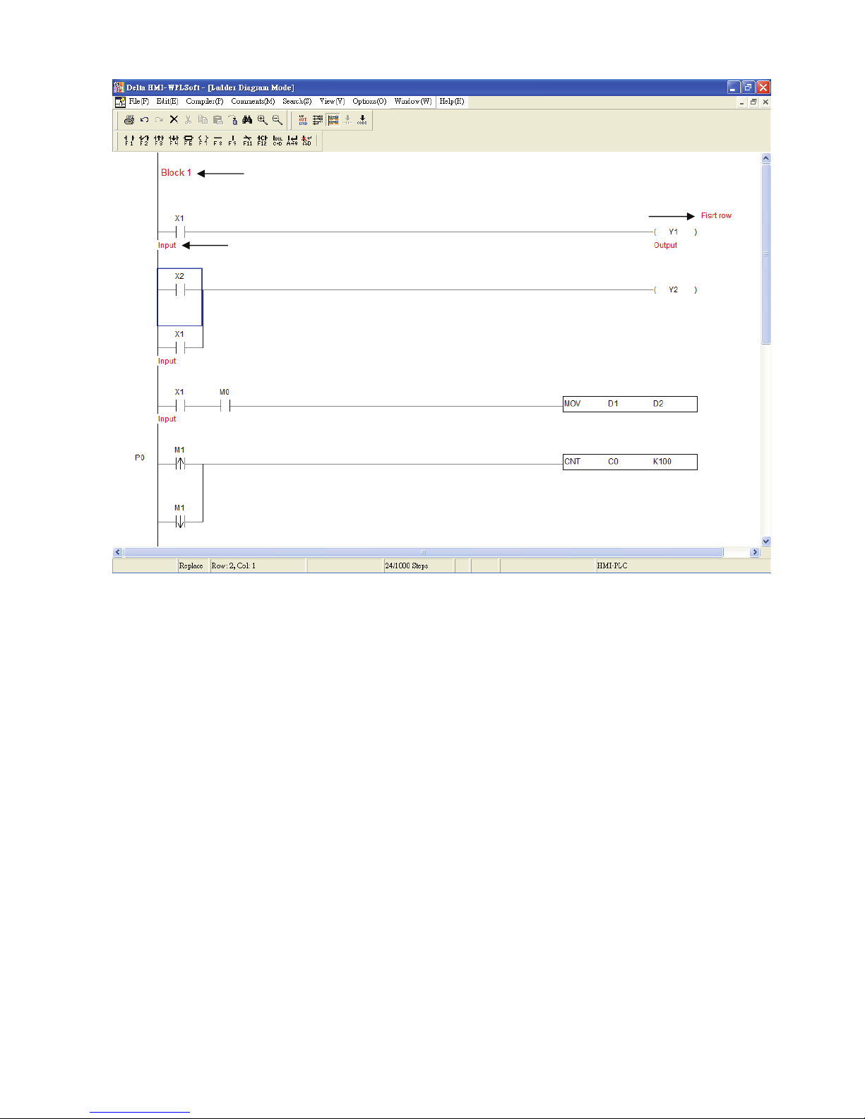
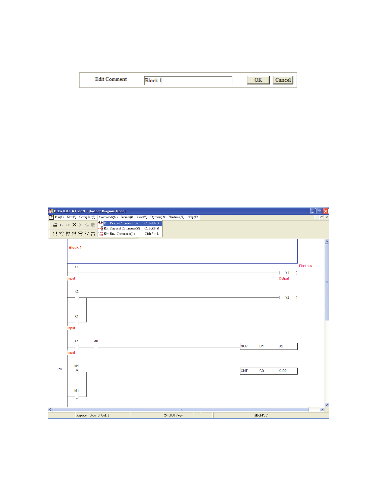
Edit Device Comments
Move the editing block on the desired device and right click the mouse. The pop-up
menu box shown on the following figure will appear. From this pop-up menu, choosing
“Edit Device Comments” can enter and edit device comments. After editing the
comments is completed, press “Enter” key on the keyboard or click the “OK” button by
using the mouse to have the record saved.
Segment Commnets
Device Comments
Row Comments
Page 44
Chapter 3 Creating and Editing Programs|DOP-EXIO Series
Revision March, 2008, Doc. Name: 2007PDD23000014 3-23
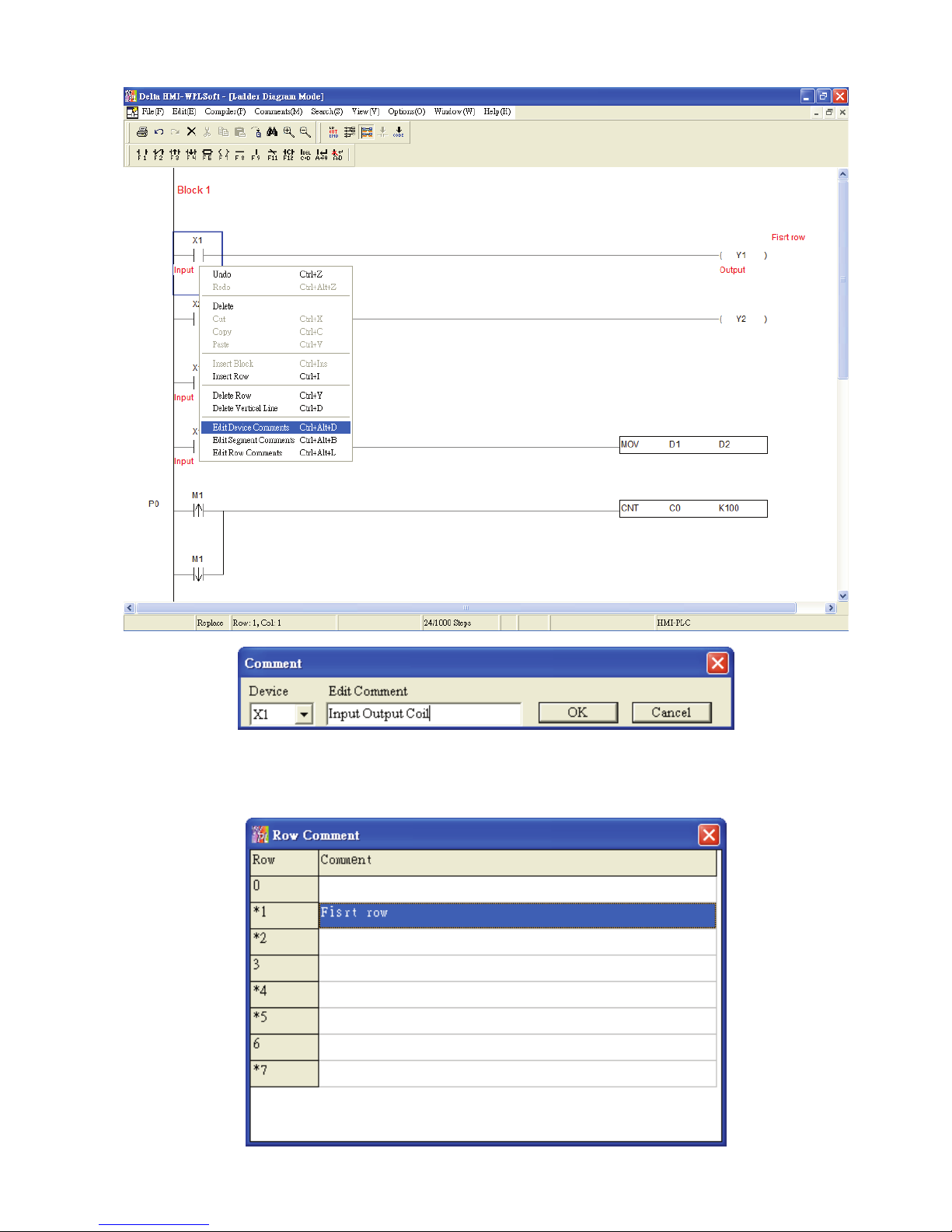
Edit Row Comments: (Only for ladder diagram mode)
Enable this function, and then the user can edit all row comments at the same time.
Page 45
Chapter 3 Creating and Editing Programs|DOP-EXIO Series
3-24
Revision March, 2008, Doc. Name: 2007PDD23000014
Edit Segment Comments: (Only for ladder diagram mode)
After editing the segment comments is completed, press the “OK” button to save the
settings.
3.6 Edit Device Comments
In the Ladder Diagram Mode and Instruction Mode, the user can set the comments to be
displayed in the device.
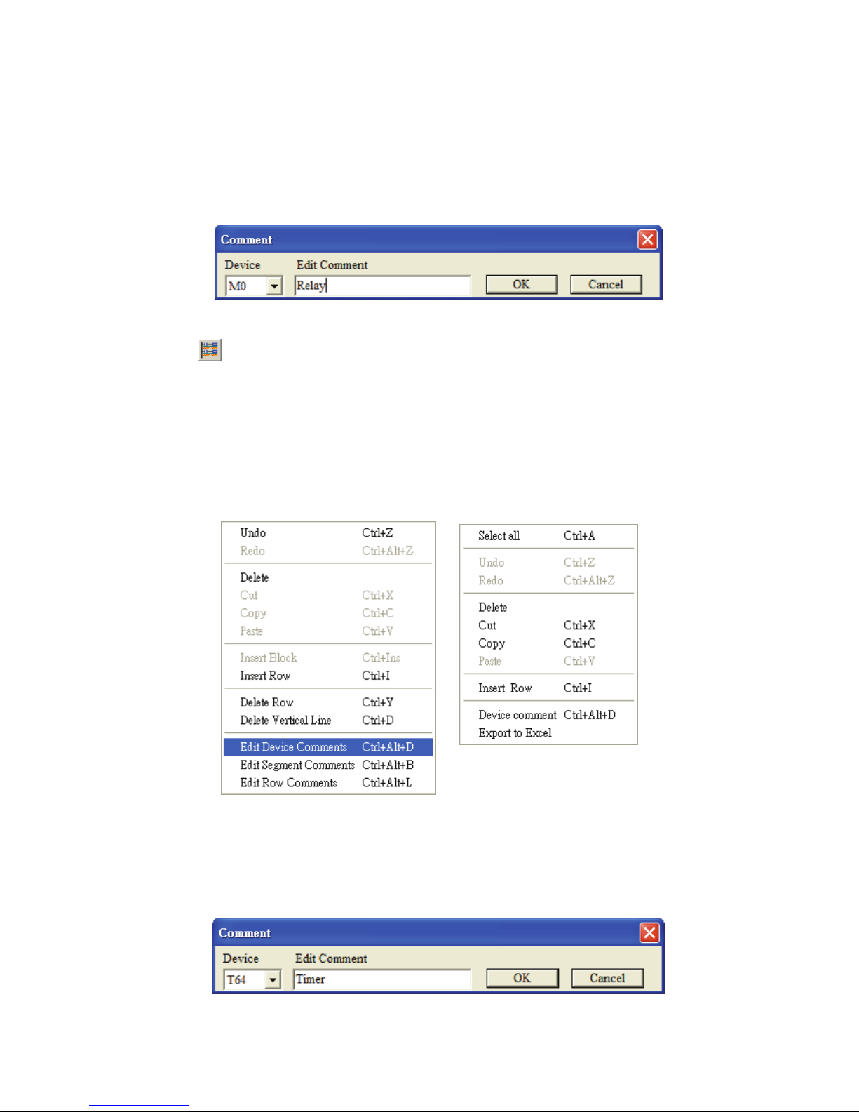
Method 1:
1. First, choose to enter the Ladder Diagram Mode (or Instruction Mode). Move the editing
block on the desired device. From the “Comments” menu, choose “Edit Device
Comments(D)” or use the keyboard shortcuts by pressing keys (Ctrl) + (Alt) + (D).
Page 46
Chapter 3 Creating and Editing Programs|DOP-EXIO Series
Revision March, 2008, Doc. Name: 2007PDD23000014 3-25
2. The Comment dialog box will appear and the user can edit comments for the desired
device that the user chooses, e.g. M0 (If the chose device is the special M and D device,
the user will see the preset comments shown in the Comment dialog box). After the device
comments editing is completed, press “Enter” key on the keyboard or click the “OK” button
by using the mouse.
3. If the user wants to display or hide device comments in the Ladder Diagram Mode, click
the icon on the toolbar or choose “Show Comments(M)” from “View(V)” menu.
Method 2:
1. Enter the Ladder Diagram Mode (or Instruction Mode). Move the editing block on the
desired device (such as T64). Right click the mouse and then the following pop-up menu
will appear on the screen.
In Ladder Diagram Mode In Instruction Mode
2. Choose “Edit Device Comments” from the pop-up menu, and the Comment dialog box will
appear (see the figure below). Select the desired device, e.g. T64 and enter the comments
for device T64. After the comments editing is completed, press “Enter” key on the
keyboard or click the “OK” button by using the mouse.
Page 47
Chapter 3 Creating and Editing Programs|DOP-EXIO Series
3-26
Revision March, 2008, Doc. Name: 2007PDD23000014
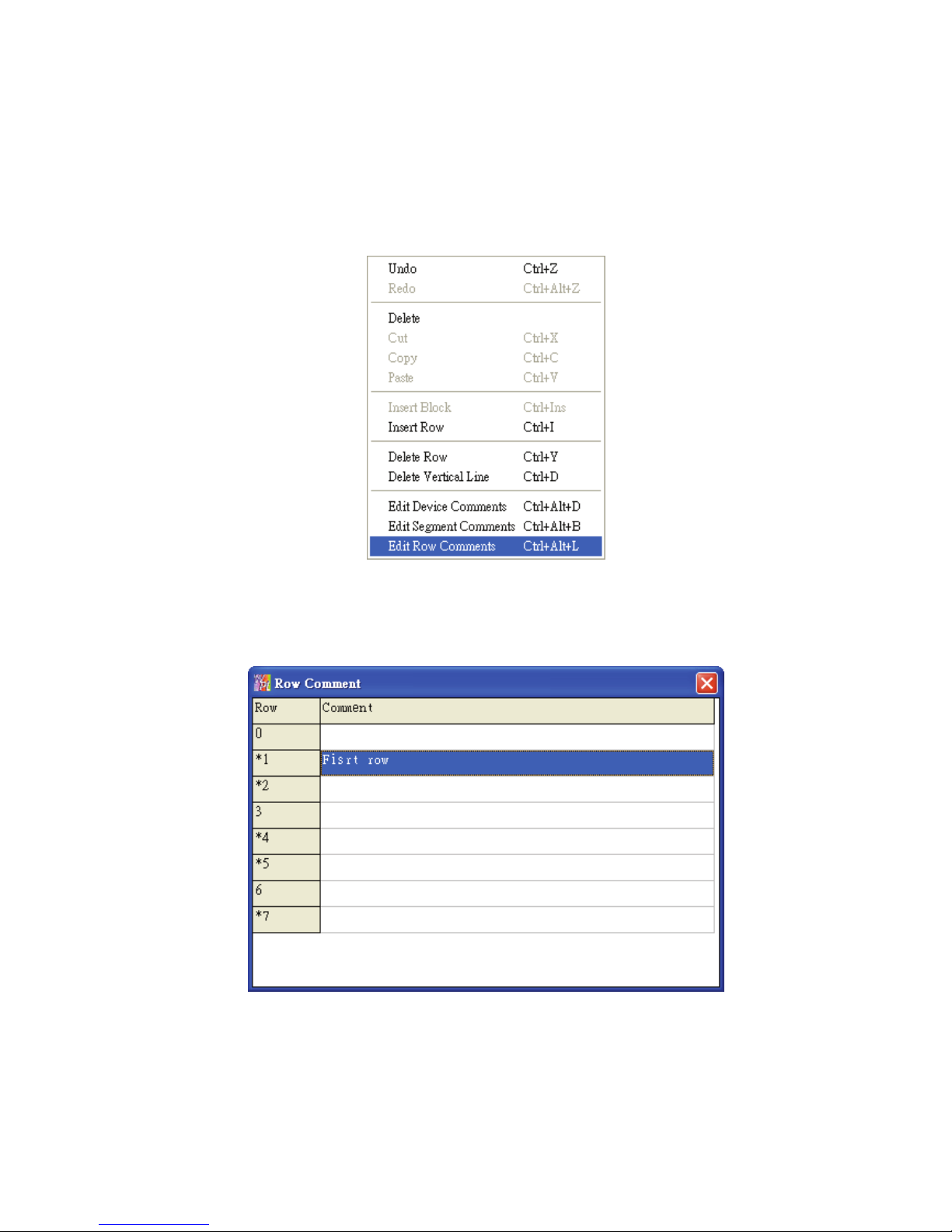
3.7 Edit Row Comments
Method 1:
1. Move the editing block to the desired row. Right click the mouse and the pop-up menu
below will appear. Select “Edit Row Comments” to add and edit comments into the row.
2. After clicking on “Edit Row Comments”, the following dialog box will appear. Then, the user
can add and edit several row comments at the same time. After the comments editing is
completed, close this dialog box to save the edited comments.
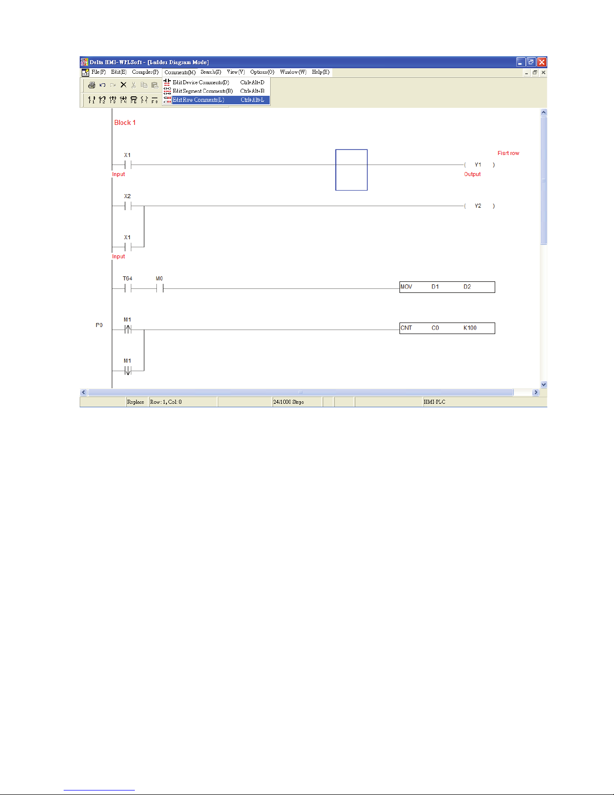
Method 2:
Move the editing block on the desired device. From “Comments” menu, choose “Edit Row
comments(L)” or use the keyboard shortcuts by pressing keys (Ctrl) + (Alt) + (L). The “Row
comment” dialog box will appear. Then, the user can enter the comments in each row. After
the row comments editing is completed, close this dialog box to save the edited comments.
Page 48
Chapter 3 Creating and Editing Programs|DOP-EXIO Series
Revision March, 2008, Doc. Name: 2007PDD23000014 3-27
3.8 Segment Comments
Method 1:
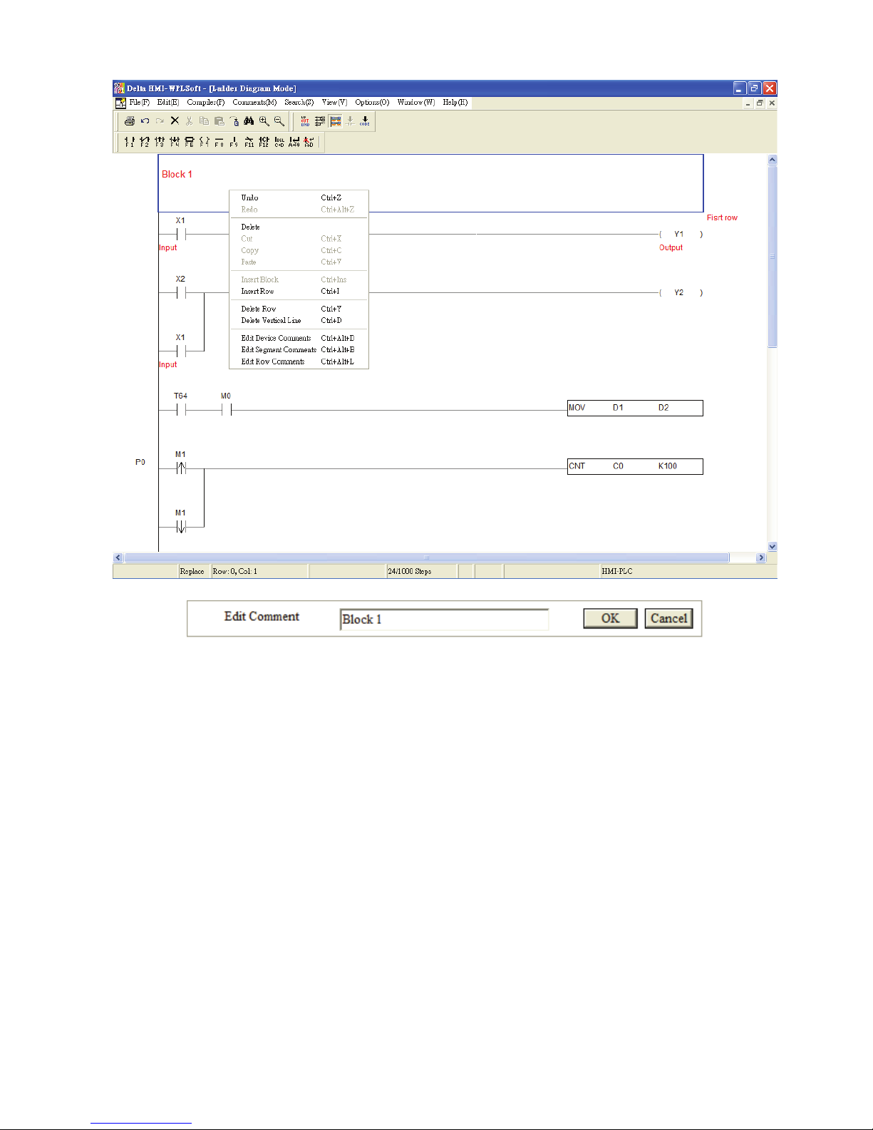
Move the editing block to the blank area that the user wants to enter the segment
comments (the user can also use the keyboard shortcuts by pressing keys (Ctrl) + (I) to
insert a new row). Right click the mouse, and the pop-up menu in the following figure will
appear. Then, choose “Edit Segment Comments” to enter the segment comments (60
characters maximum). Finally, press the “OK” button to complete the editing.
Page 49
Chapter 3 Creating and Editing Programs|DOP-EXIO Series
3-28
Revision March, 2008, Doc. Name: 2007PDD23000014
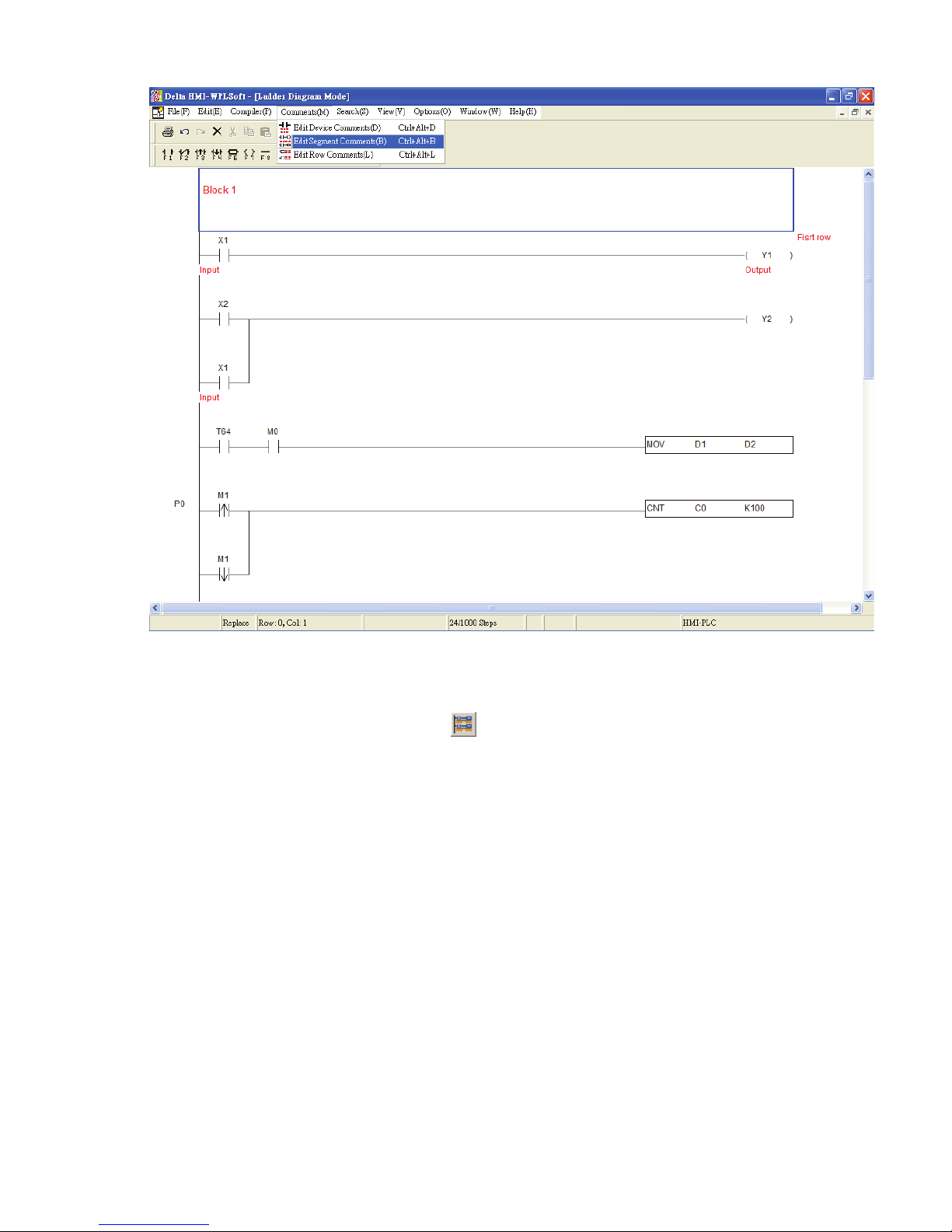
Method 2:
Click “Comment” from the menu bar, and choose “Edit Segment Comments(B)” or use the
keyboard shortcuts by pressing keys (Ctrl) + (Alt) + (B) to enter and edit the segment
comments.
Page 50
Chapter 3 Creating and Editing Programs|DOP-EXIO Series
Revision March, 2008, Doc. Name: 2007PDD23000014 3-29
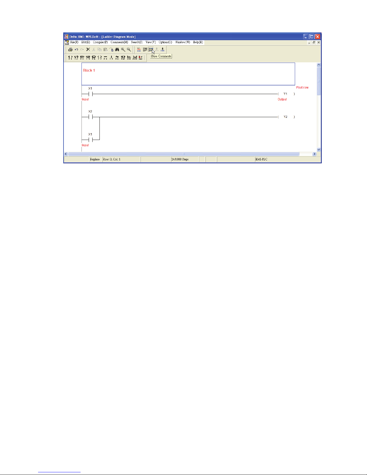
Show or Hide Comments
The user can show and hide the comment by clicking “View(V)” > “Show
Comments(M)” or clicking the icon
on the toolbar. However, this function is
provided for device comments and row comments only. The user cannot show and hide
segment comments by using this function. When this function is enabled, the height of
the ladder diagram will become higher in order to display the comments.
Page 51
Chapter 3 Creating and Editing Programs|DOP-EXIO Series
3-30
Revision March, 2008, Doc. Name: 2007PDD23000014
Page 52
Chapter 4 I/O Point Indicators|DOP-EXIO Series
Revision March, 2008, Doc. Name: 2007PDD23000014 4-1
Chapter 4 I/O Point Indicators
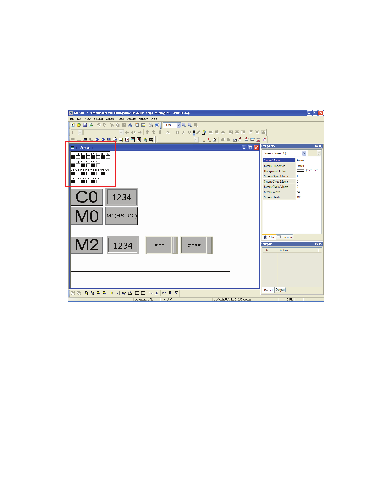
In the editing environment of ScrEdit (Screen Editor) programming software, the user can use
digital input/output point indicators (hereinafter called “I/O point indicators”) to display the
status of the input and output points and monitor the operation of DOP-EXIO series. Please
refer to the Fig. 4.1 below.
Fig. 4.1 Status of I/O point indicators
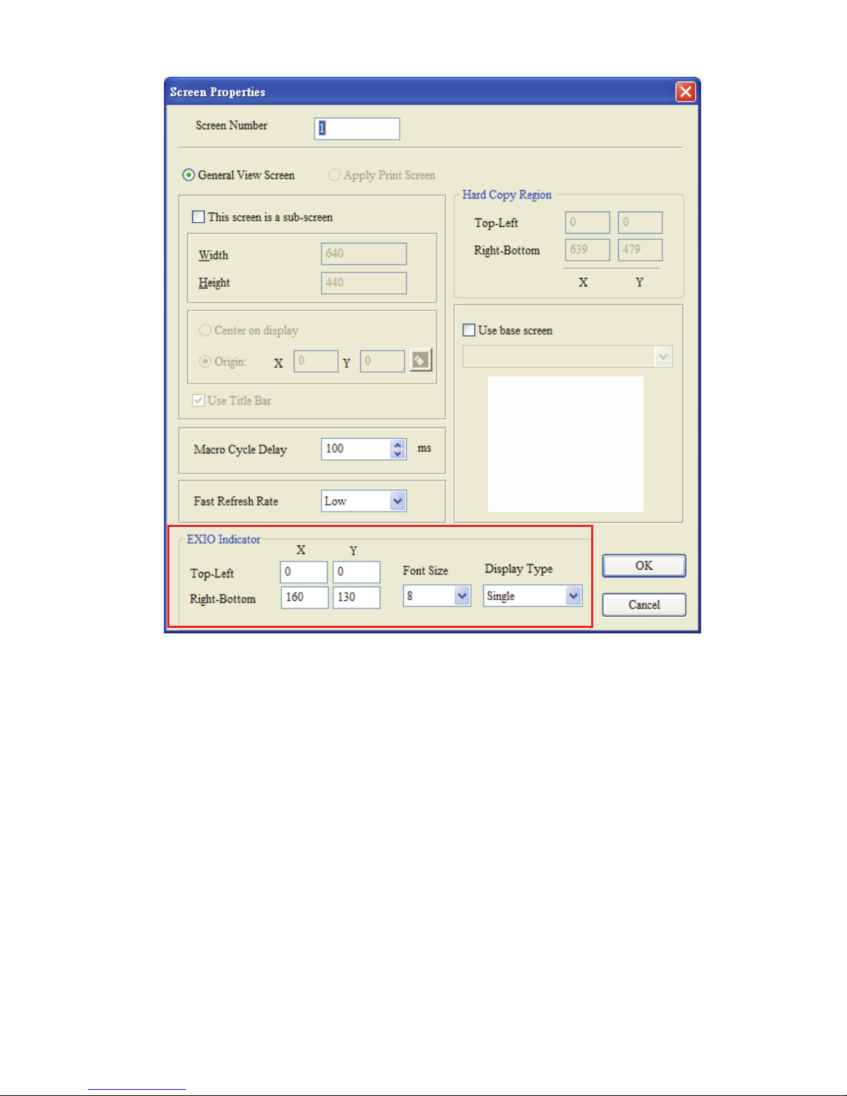
After opening the “Screen Properties” dialog box, which provides screen property settings for
each screen, the user can set the settings of the I/O point indicators. Please refer to Fig. 4.2 in
the following page.
Page 53
Chapter 4 I/O Point Indicators|DOP-EXIO Series
4-2
Revision March, 2008, Doc. Name: 2007PDD23000014
Fig. 4.2 “Screen Properties” dialog box
1. Display Position:
Determine the position of the I/O point indicators by setting the coordinates of the
Top-Left and Right-Bottom points.
2. Font Size:
Determine the font size of the font which displays in the I/O point indicators. (The
available selection includes 8, 10, 12, 14, 16, 18, 20, 24, 28, 32, 40, 48, 64.)
3. Display Type:
There are three kinds of display types: None, Single and All.
The display of the indicators will change depending on the settings of the screen
properties.
Page 54

Chapter 4 I/O Point Indicators|DOP-EXIO Series
Revision March, 2008, Doc. Name: 2007PDD23000014 4-3
None: When the user selects this option, the indicators will not show on the screen.
Single: When the user selects this option, the indicators will display on a certain screen
only.
All: When the user selects this option, the indicators will display on all screens.
Page 55

Chapter 4 I/O Point Indicators|DOP-EXIO Series
4-4
Revision March, 2008, Doc. Name: 2007PDD23000014
This page intentionally left blank.
Page 56
Chapter 5 Internal Memory Address|DOP-EXIO Series
Revision March, 2008, Doc. Name: 2007PDD23000014 5-1
Chapter 5 Internal Memory Address
After enabling the DOP-EXIO function, all the HMI elements can use DOP-EXIO series as
internal memory addresses. The usage is the same as the usage of HMI internal memory $0 ~
$65535. Some of the internal memory addresses are “For latched”. For more introductions
and the setting range of each device, please refer to Appendix A in this manual.
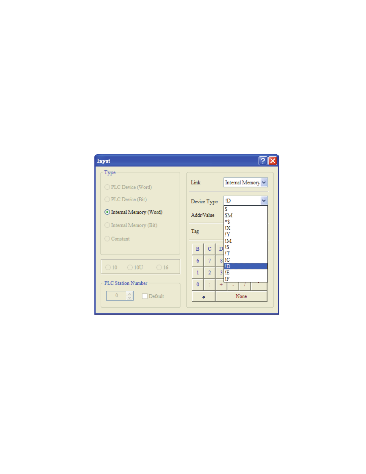
When the function for DOP-EXIO series is activated, the devices for DOP-EXIO series will
appear in the “Device Type” drop-down menu shown in the “Internal Memory” selection.Some
of the devices have special definitions and will be set or referred within some specific
instructions. For more descriptions of the devices and instructions for DOP-EXIO series,
please refer to Appendixes in this manual.
Page 57

Chapter 5 Internal Memory Address|DOP-EXIO Series
5-2
Revision March, 2008, Doc. Name: 2007PDD23000014
This page intentionally left blank.
Page 58

Appendix A List of Devices|DOP-EXIO Series
Revision March, 2008, Doc. Name: 2007PDD23000014 A-1
Appendix A List of Devices
Type Device Item Range Function
X0~X7, 8 points, octal DOP-EXIO14RAE
Corresponds to
external input point.
X Input relay
X0~X17, 16 points, octal DOP-EXIO28RAE
Corresponds to
external input point.
Y0~Y5, 6 points, octal DOP-EXIO14RAE Internal output point.
Y Output relay
Y0~Y5, Y10~Y15, 12
points, octal
DOP-EXIO28RAE Internal output point.
General
puspose
M0~M511, M768~M999,
744 points; M1000~
M1279, 280 points
*2
M
Auxiliary
Relay
Latched
*1
M512~M767, 256 points
Tot a l is
1,280 points
The contacts can be
ON/OFF in the
program.
100ms T0~T63, 64 points
10ms T64~T126, 63 points
T Timer
1ms T127, 1 point
Tot a l is
128 points
Timer indicated by
TMR instruction. If
timing reaches its
target, the T contact
of the same number
will be On.
C0~C111, 112 points
16-bit
counting up
C112~C127, 16 points
Tot a l is
128 points
C Counter
32-bit
counting
up/down
(Latched
*1
)
C235,C236,C237,C238,
C241,C242,C244,C246,
C247,C249,C251,C252,
C254, 13 points
Tot a l is
13 points
Counter indicated by
CNT (DCNT)
instruction. If
counting reaches its
target, the C contact
of the same number
will be On.
Relay (bit)
S Step point
Latched
*1
S0~S127, 128 points
Tot a l is
128 points
Used for step ladder
diagram
Register (word data)
T Present value of timer T0~T127, 128 points
When the timing
reaches the target,
the contact of the
timer will
be On.
Page 59
Appendix A List of Devices|DOP-EXIO Series
A-2
Revision March, 2008, Doc. Name: 2007PDD23000014
Type Device Item Range Function
C Present value of counter
C0~C127, 16-bit counter, 128 points
C235,C236,C237,C238, C241,C242, C244,
C246, C247,C249,C251,C252, C254, 32-bit
counter, 13 points
When the ounting
reaches the arget,
the contact of the
counter will be On.
General
purpose
D0~D407, 408 points
Latched*1 D408~D599, 192 points
Total is 600 points
Register (word data)
D
Data
register
Index
indication
E, F, 2 points Total is 2 points
Memory area for data
storage; E, F can be
used for index
indication.
N
For master control
nested loop
N0~N7, 8 points
Control point for main
control loop.
Pointer
P
For CJ, CALL
instructions
P0~P63, 64 points
Position index for CJ
and CALL.
K Decimal form
K-32,768 ~ K32,767 (16-bit operation)
K-2,147,483,648 ~ K2,147,483,647 (32-bit operation)
Constant
H Hexadecimal form
H0000 ~ HFFFF (16-bit operation)
H00000000 ~ HFFFFFFFF (32-bit operation)
*1: The latched area is fixed and cannot be changed.
*2: M1000, M1001, M1002, M1003, M1020, M1021, M1022, M1067, M10068, and M1161 are the special auxiliary relays (special M).
Special Auxiliary Relay
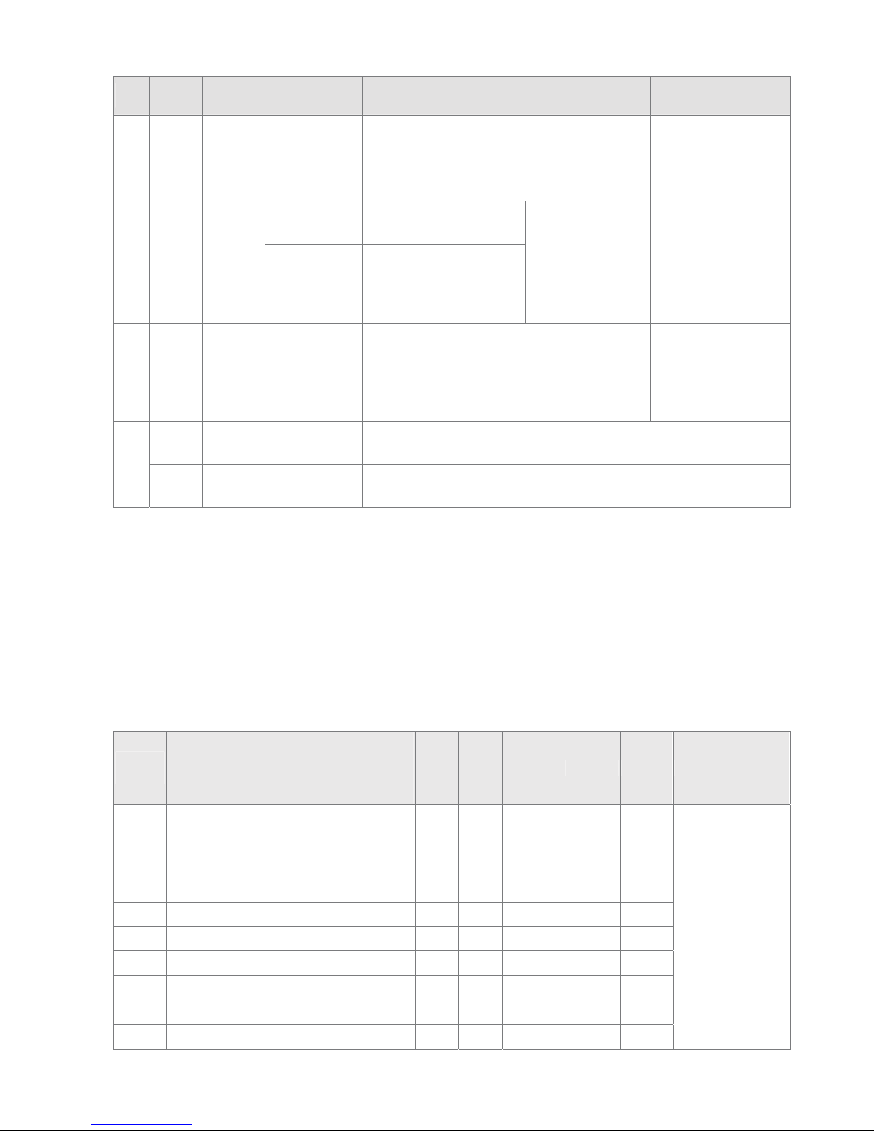
The types and functions of special auxiliary relays (special M) are listed in the table below.
Please be noted that the columns marked with “R” refers to “read only”, “and “R/W” refers to
“read and write” and “-“ refers to the status remains unchanged.
Special
M
Function
Power Off
Ø
Power On
STOP
Ø
RUN
RUN
Ø
STOP
Attribute Latched Default Applicable Model
M1000
Monitoring normally open
contact (A)
*1
Off On Off R No Off
M1001
Monitoring normally closed
contact (B)
*2
On Off On R No On
M1002 Enabling positive pulses
*3
Off On Off R No Off
M1003 Enabling negative pulses
*4
On Off On R No On
M1020 Zero flag Off - - R No Off
M1021 Borrow flag Off - - R No Off
M1022 Carry flag Off - - R No Off
M1067 Calculation error Off Off - R No Off
DOP-EXIO14RAE
DOP-EXIO28RAE
Page 60

Appendix A List of Devices|DOP-EXIO Series
Revision March, 2008, Doc. Name: 2007PDD23000014 A-3
Special
M
Function
Power Off
Ø
Power On
STOP
Ø
RUN
RUN
Ø
STOP
Attribute Latched Default Applicable Model
M1068 Calculation error locked Off - - R No Off
M1161
8/16 bit mode switch
On: in 8-bit mode
Off - - R/W No Off
DOP-EXIO14RAE
DOP-EXIO28RAE
*1: M1000 (A contact) is constantly “On” during operation and detection. When ELC is in RUN status, M1000 remains “On”.
*2: M1001 (B contact) is constantly “Off” during operation and detection. When ELC is in RUN status, M1001 remains “Off”
*3: M1002 is “On” during the first scan when ELC starts to RUN and remains “Off” afterward. The pulse width = 1 scan time. Use this contact
for all kinds of initial settings. (On immediately when RUN).
*4: M1003 is “Off” during the first scan when ELC starts to RUN and remains “On” afterward. M1003 enables negative-direction pulses. (“Off”
immediately when RUN)
Page 61

Appendix A List of Devices|DOP-EXIO Series
A-4
Revision March, 2008, Doc. Name: 2007PDD23000014
This page intentionally left blank.
Page 62

Appendix B List of Instructions|DOP-EXIO Series
Revision March, 2008, Doc. Name: 2007PDD23000014 B-1
Appendix B List of Instructions
Available Instructions
16-bit Instruction 32-bit Instruction Function
LD - Loading in A contact
LDI - Loading in B contact
AND - Series Connection- A Contact
ANI - Series Connection- B Contact
OR - Parallel Connection- A Contact
ORI - Parallel Connection- B Contact
ANB - Series connection- loop blocks
ORB - Parallel connection- loop blocks
MPS DMOV Store the current result of the internal EXIO operations
MRD DCML Read the current result of the internal EXIO operations
ANDP - Rising-edge Series Connection
ANDF DFMOV Falling-edge Series Connection
ORP DXCH Rising-edge Parallel Connection
ORF DBCD Falling-edge Parallel Connection
PLS DBIN Rising-edge Output
PLF DADD Falling-edge Output
END DSUB Program End
NOP DMUL No Operation
INV DRCL Inverting Operation
P - Pointer
MOV - Move
CML - Compliment
BMOV - Block Move
FMOV - Fill Move
XCH - Exchange
BCD - Binary Coded Decimal
BIN - Binary
ADD - Addition
SUB - Subtraction
MUL - Multiplication
RCL - Rotation Left with Carry
SFTR - Bit Shift Right
SFTL - Bit Shift Left
ZRST - Zero Reset
Page 63

Appendix B List of Instructions|DOP-EXIO Series
B-2
Revision March, 2008, Doc. Name: 2007PDD23000014
Available Instructions
16-bit Instruction 32-bit Instruction Function
SUM DSUM Sum of Active Bits
BON DBON Check Specified Bit Status
MEAN DMEAN Mean
REF - Refresh
ALT - Alternate State
ASCI - Convert Hex to ASCII
AND= DAND= Series Connection Contact Compare =
AND> DAND> Series Connection Contact Compare >
AND< DAND< Series Connection Contact Compare <
AND<> DAND<> Series Connection Contact Compare <>
AND<= DAND<= Series Connection Contact Compare <=
AND>= DAND>= Series Connection Contact Compare >=
MPP - Pop (recall and remove) the currently stored result
OUT - Output Coil
SET -
Latch(ON)
RST - Clear the contacts or the registers
TMR - 16-bit Timer
CNT DCNT 16-bit / 32-bit Counter
MC - Master Control Start
MCR - Master Control Reset
LDP - Rising-edge Detection Operation
LDF - Falling-edge Detection Operation
STL - Step Transition Ladder Start Command
RET - Step Transition Ladder Return Command
CJ - Conditional Jump
CALL - Call Subroutine
SRET - Subroutine Return
FEND - The End of the Main Program (First End)
FOR - Start of a FOR-NEXT Loop
NEXT - End of a FOR-NEXT Loop
CMP DCMP Compare
ZCP DZCP Zone Compare
DIV DDIV Division
INC DINC Increment
DEC DDEC Decrement
WAND DAND Logical Word AND
WOR DOR Logical Word OR
Page 64

Appendix B List of Instructions|DOP-EXIO Series
Revision March, 2008, Doc. Name: 2007PDD23000014 B-3
Available Instructions
16-bit Instruction 32-bit Instruction Function
WXOR DXOR Logical Exclusive OR
NEG DNEG 2’s Complement (Negative)
ROR DROR Rotation Right
ROL DROL Rotation Left
RCR DRCR Rotation Right with Carry
HEX - Convert ASCII to Hex
ABS DABS Absolute Value
SWAP DSWAP Byte Swap
LD= DLD= Load Contact Compare =
LD> DLD> Load Contact Compare >
LD< DLD< Load Contact Compare <
LD<> DLD<> Load Contact Compare <>
LD<= DLD<= Load Contact Compare <=
LD>= DLD>= Load Contact Compare >=
OR= DOR= Parallel Connection Contact Compare =
OR> DOR> Parallel Connection Contact Compare >
OR< DOR< Parallel Connection Contact Compare <
OR<> DOR<> Parallel Connection Contact Compare <>
OR<= DOR<= Parallel Connection Contact Compare <=
OR>= DOR>= Parallel Connection Contact Compare >=
Page 65

Appendix B List of Instructions|DOP-EXIO Series
B-4
Revision March, 2008, Doc. Name: 2007PDD23000014
This page intentionally left blank.
Page 66
Appendix C Use of Basic Instructions|DOP-EXIO Series
Revision March, 2008, Doc. Name: 2007PDD23000014 C-1
Appendix C Use of Basic Instructions
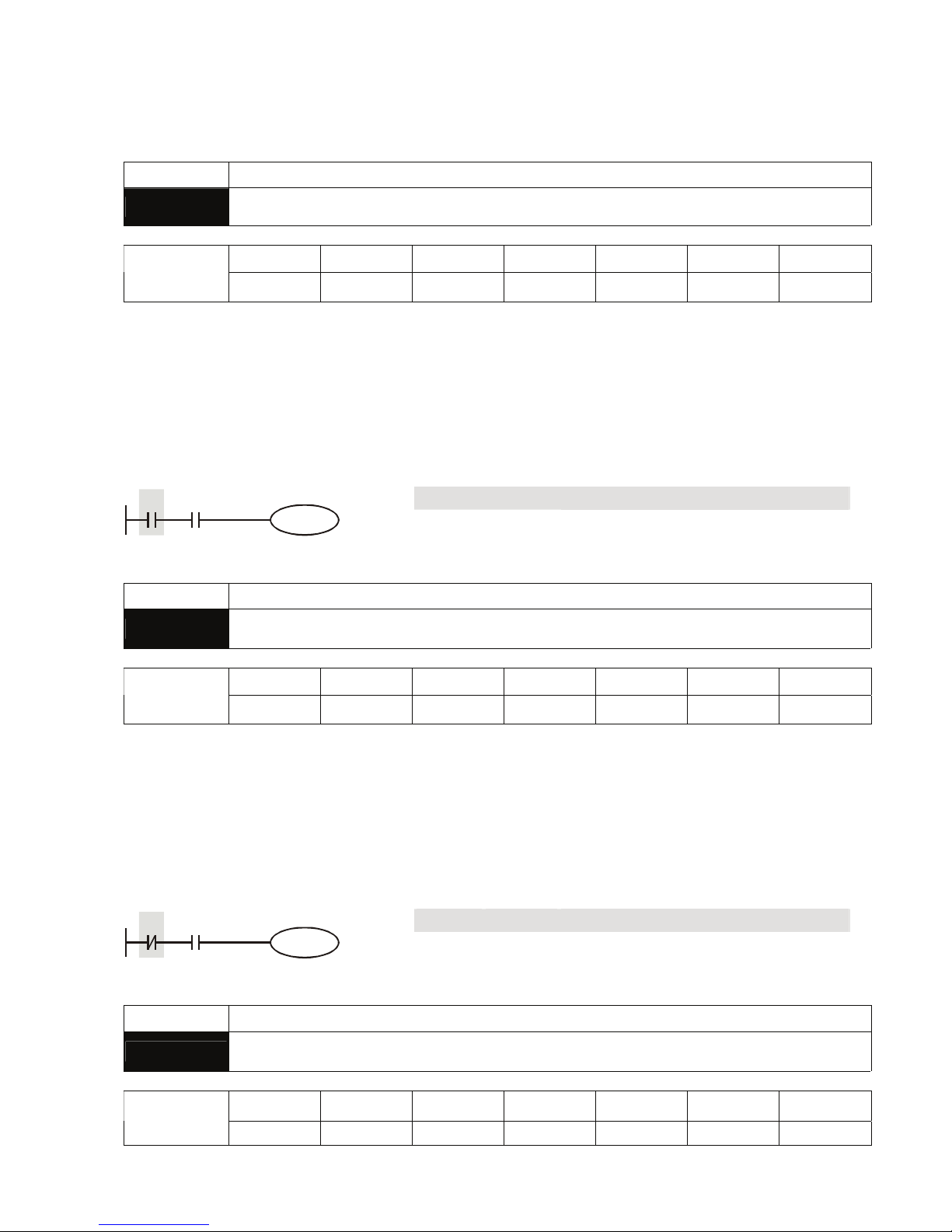
Mnemonic Functions
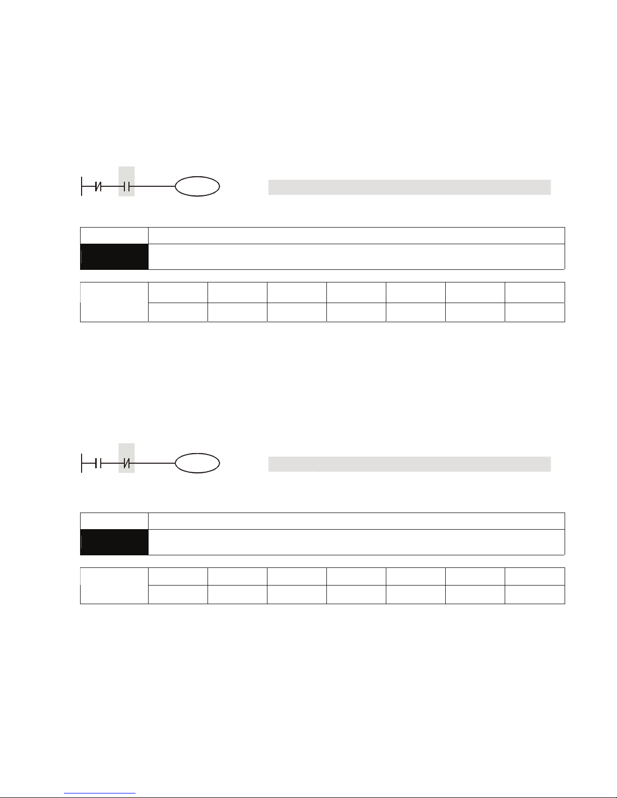
LD
Loading in A contact
X0~X17 Y0~Y17 M0~M1279 S0~S127 T0~T127 C0~C254 D0~D599
Operand
9 9 9 9 9 9
-
Explanation:
The LD instruction is used on the A contact that has its start from the left BUS or the A contact that is
the start of a contact circuit. The functions are to save the present contents and store the acquired
contact status into the accumulative register.
Program Example:
Ladder diagram: Instruction code: Operation:
LD X0
Loading in contact A of X0
AND X1 Connecting to contact A of X1 in series
X0 X1
Y1
OUT Y1 Driving Y1 coil
Mnemonic Functions
LDI
Loading in B contact
X0~X17 Y0~Y17 M0~M1279 S0~S127 T0~T127 C0~C254 D0~D599
Operand
9 9 9 9 9 9
-
Explanation:
The LDI instruction is used on the B contact that has its start from the left BUS or the B contact that is
the start of a contact circuit. The functions are to save the present contents and store the acquired
contact status into the accumulative register.
Program Example:
Ladder diagram: Instruction code: Operation:
LDI X0 Loading in contact B of X0
AND X1 Connecting to contact A of X1 in series
X0 X1
Y1
OUT Y1 Driving Y1 coil
Mnemonic Functions
AND
Series Connection- A Contact
X0~X17 Y0~Y17 M0~M1279 S0~S127 T0~T127 C0~C254 D0~D599
Operand
9 9 9 9 9 9
-
Page 67
Appendix C Use of Basic Instructions|DOP-EXIO Series
C-2
Revision March, 2008, Doc. Name: 2007PDD23000014
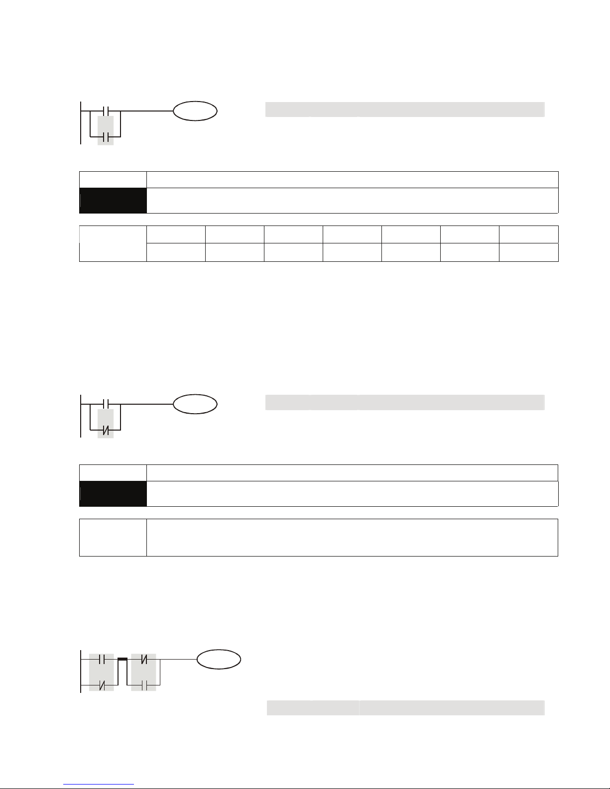
Explanation:
The AND instruction is used in the series connection of A contact. The functions are to read out the
status of present specific series connection contacts and perform the “AND” operation with the logical
operation result obtained. The final result will be store in the accumulative register.
Program Example:
Ladder diagram: Instruction code: Operation:
LDI X1 Loading in contact B of X1
AND X0 Connecting to contact A of X0 in series
X0X1
Y1
OUT Y1 Driving Y1 coil
Mnemonic Functions
ANI
Series Connection- B Contact
X0~X17 Y0~Y17 M0~M1279 S0~S127 T0~T127 C0~C254 D0~D599
Operand
9 9 9 9 9 9
-
Explanation:
The ANI instruction is used in the series connection of B contact. The functions are to read out the
status of present designated series connection contacts and perform the “AND” operation with the
logical operation result obtained. The final result will be store in the accumulative register.
Program Example:
Ladder diagram: Instruction code: Operation:
LD X1 Loading in contact A of X1
ANI X0 Connecting to contact B of X0 in series
X0X1
Y1
OUT Y1 Driving Y1 coil
Mnemonic Functions
OR
Parallel Connection- A Contact
X0~X17 Y0~Y17 M0~M1279 S0~S127 T0~T127 C0~C254 D0~D599
Operand
9 9 9 9 9 9
-
Explanation:
The OR instruction is used in the parallel connection of A contact. The functions are to read out the
status of present designated parallel connection contacts and perform the “OR” operation with the
logical operation result obtained. The final result will be store in the accumulative register.
Page 68
Appendix C Use of Basic Instructions|DOP-EXIO Series
Revision March, 2008, Doc. Name: 2007PDD23000014 C-3
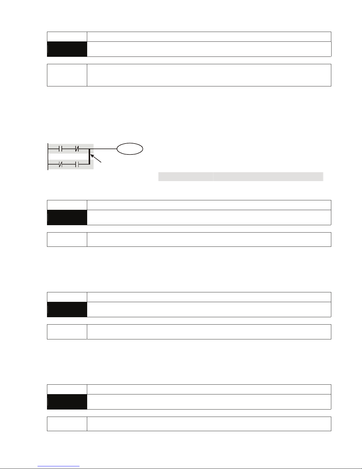
Program Example:
Ladder diagram: Instruction code: Operation:
LD X0 Loading in contact A of X0
OR X1 Connecting to contact A of X1 in parallel
X0
X1
Y1
OUT Y1 Driving Y1 coil
Mnemonic Functions
ORI
Parallel Connection- B Contact
X0~X17 Y0~Y17 M0~M1279 S0~S127 T0~T127 C0~C254 D0~D599
Operand
9 9 9 9 9 9
-
Explanation:
The ORI instruction is used in the parallel connection of B contact. The functions are to read out the
status of present designated parallel connection contacts and perform the “ORI” operation with the
logical operation result obtained. The final result will be store in the accumulative register.
Program Example:
Ladder diagram: Instruction code: Operation:
LD X0 Loading in contact A of X0
ORI X1 Connecting to contact B of X1 in parallel
X0
X1
Y1
OUT Y1 Driving Y1 coil
Mnemonic Functions
ANB
Series connection- loop blocks
Operand none
Explanation:
To perform the “AND” operation of the preserved logic results and content in the accumulative register.
Program Example:
Ladder diagram: Instruction code: Operation:
LD X0 Loading in contact A of X0
ORI X2 Connecting to contact B of X2 in parallel
LDI X1 Loading in contact B of X1
OR X3 Connecting to contact A of X3 in parallel
ANB Connecting circuit block in series
X0
X2
Y1
X1
X3
ANB
Block A Block B
OUT Y1 Driving Y1 coil
Page 69
Appendix C Use of Basic Instructions|DOP-EXIO Series
C-4
Revision March, 2008, Doc. Name: 2007PDD23000014
Mnemonic Functions
ORB
Parallel connection- loop blocks
Operand None
Explanation:
To perform the “OR” operation of the preserved logic results and content in the accumulative register.
Program Example:
Ladder diagram: Instruction code: Operation:
LD X0 Loading in contact A of X0
ANI X1 Connecting to contact B of X1 in series
LDI X2 Loading in contact B of X2
AND X3 Connecting to contact A of X3 in series
ORB Connecting circuit block in parallel
X0
X2
Y1
X1
X3
ORB
Block A
Block B
OUT Y1 Driving Y1 coil
Mnemonic Functions
MPS
Store the current result of the internal EXIO operations
Operand None
Explanation:
To save the content in the accumulative register into the operational result (the pointer of operational
result will plus 1).
Mnemonic Functions
MRD
Read the current result of the internal EXIO operations
Operand None
Explanation:
To read the operational result and store it into the accumulative register (the pointer of operational
result stays intact).
Mnemonic Functions
MPP
Pop (recall and remove) the currently stored result
Operand None
Page 70
Appendix C Use of Basic Instructions|DOP-EXIO Series
Revision March, 2008, Doc. Name: 2007PDD23000014 C-5
Explanation:
To retrieve the previous preserved logical operation result and store it into the accumulative register
(the pointer of operational result will minus 1).
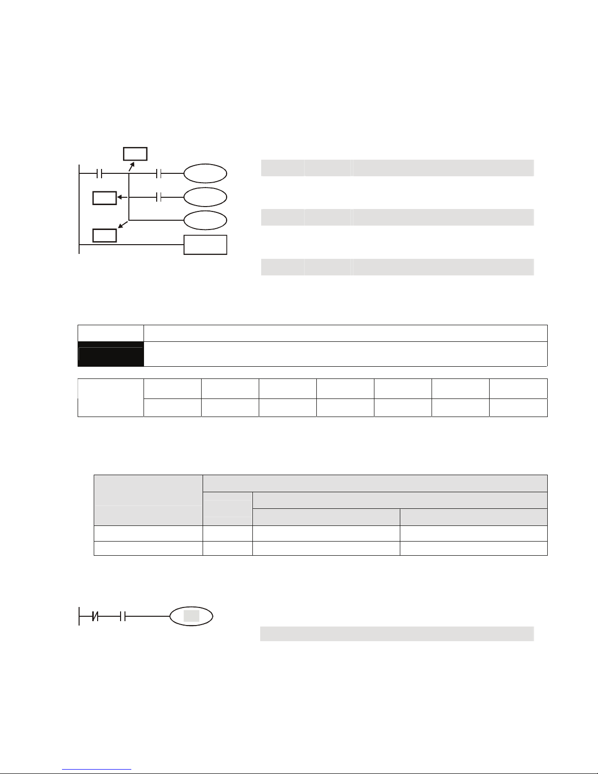
Program Example:
Ladder diagram: Instruction code: Operation:
LD X0 Loading in contact A of X0
MPS
Saving into stack
AND X1 Connecting to contact A of X1 in series
OUT Y1 Driving Y1 coil
MRD
Reading from stack
AND X2 Connecting to contact A of X2 in series
OUT M0 Driving M0 coil
MPP
Reading from stack and pop pointer
OUT Y2 Driving Y2 coil
X0
Y1
X1
M0
X2
Y2
END
MPP
MRD
MPS
END Program ends
Mnemonic Functions
OUT
Output Coil
X0~X17 Y0~Y17 M0~M1279 S0~S127 T0~T127 C0~C254 D0~D599
Operand
-
9 9 9
- - -
Explanations:
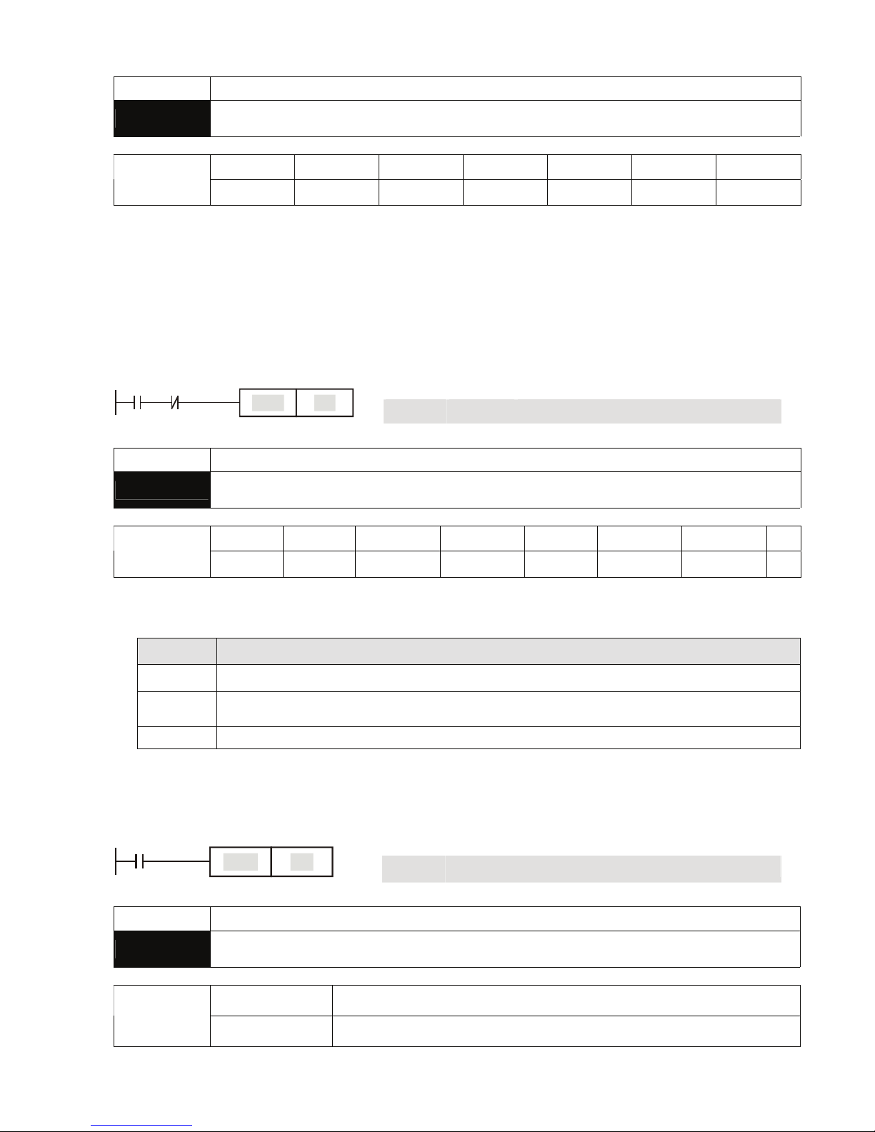
1. To output the logical operation result before OUT instruction into a designated device.
2. Actions of coil contact:
OUT instruction
Contact
Operational result
Coil
A contact (normally open) B contact (normally closed)
FALSE Off Off On
TRUE On On Off
Program Example:
Ladder diagram: Instruction code: Operation:
LDI X0 Loading in contact B of X0
AND X1 Connecting to contact A of X1 in series
X0 X1
Y1
OUT Y1 Driving Y1 coil
Page 71
Appendix C Use of Basic Instructions|DOP-EXIO Series
C-6
Revision March, 2008, Doc. Name: 2007PDD23000014
Mnemonic Functions
SET
Latch (ON)
X0~X17 Y0~Y17 M0~M1279 S0~S127 T0~T127 C0~C254 D0~D599
Operand
-
9 9 9
- - -
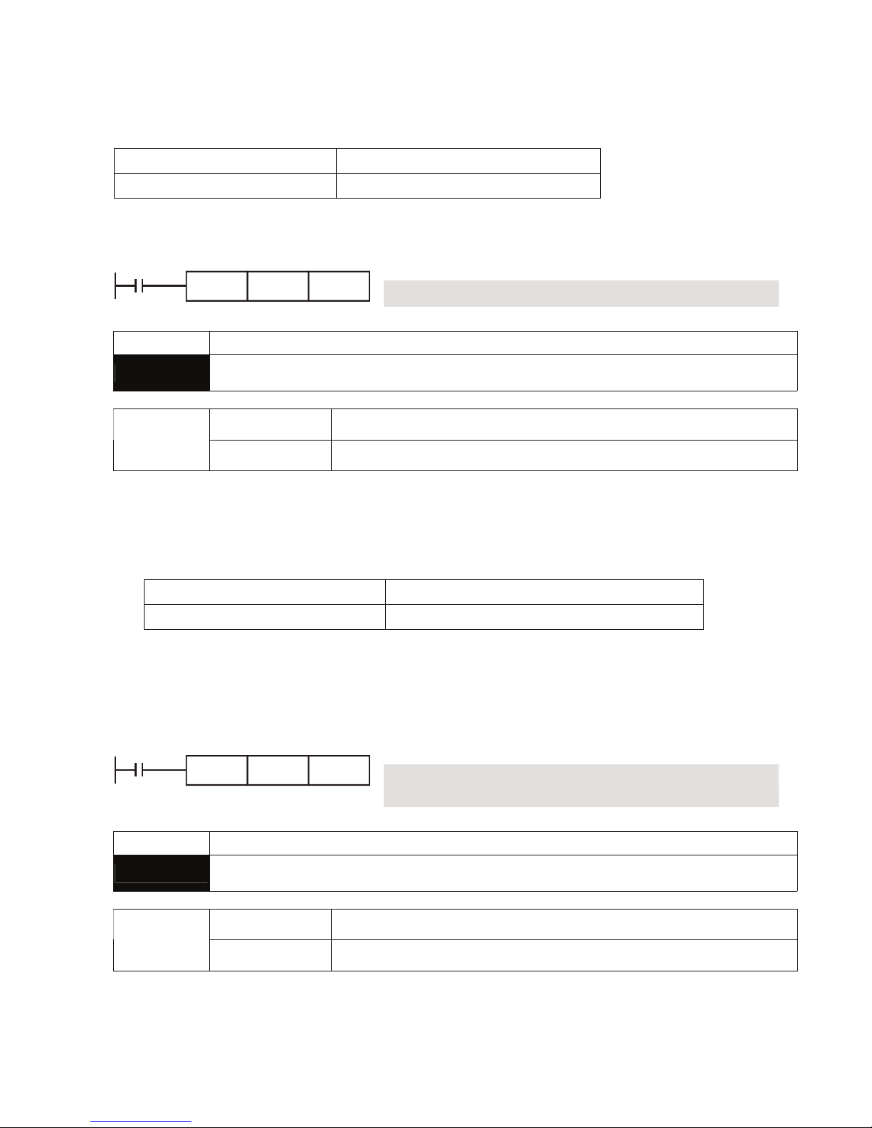
Explanations:
When the SET instruction is driven, its designated device will be “On” and keep being On both when
SET instruction is still being driven or not driven. Use RST instruction to set “Off” the device.
Program Example:
Ladder diagram: Instruction code: Operation:
LD X0 Loading in contact A of X0
ANI Y0 Connecting to contact B of Y0 in series
X0 Y0
Y1
SET
SET Y1
Y1 latched (On)
Mnemonic Functions
RST
Clear the contact or the registers
X0~X17 Y0~Y17 M0~M1279 S0~S127 T0~T127 C0~C254 D0~D599 E, F
Operand
-
9 9 9 9 9 9 9
Explanations:
1. When the RST instruction is driven, the actions of the designated devices are:
Device Status
Y, M, S, Coil and contact will be set to “Off”
T, C
Present values of the timer or counter will be set to “0”, and the coil and contact will be
set to “Off”
D, E, F The content will be set to “0”.
2. If RST instruction is not being executed, the status of the designated device will stay intact.
Program Example:
Ladder diagram: Instruction code: Operation:
LD X0 Loading in contact A of X0
X0
Y5
RST
RST Y5 Resetting contact Y5
Mnemonic Functions
TMR
16-bit Timer
T-K
T0~T127, K0~K32,767
Operand
T-D
T0~T127, D0~D599
Page 72
Appendix C Use of Basic Instructions|DOP-EXIO Series
Revision March, 2008, Doc. Name: 2007PDD23000014 C-7
Explanations:
When TMR instruction is executed, the designated coil of the timer will be On and the timer will start to
time. When the set value in the timer is reached (present ≥ set value), the contact will be:
NO (Normally Open) contact Open collector
NC (Normally Closed) contact Close collector
Program Example:
Ladder diagram: Instruction code: Operation:
LD X0 Loading in contact A of X0 T5 timer
X0
T5TMR
K1000
TMR T5 K1000 Set value in timer T5 as K1,000
Mnemonic Functions
CNT
16-bit Counter
C-K
C0~C127, K0~K32,767
Operand
C-D
C0~C127, D0~D599
Explanations:
1. When the CNT instruction goes from Off to On, the designated counter coil will be driven, and the
present value in the counter will plus 1. When the counting reaches the set value (present value =
set value), the contact will be:
NO (Normally Open) contact Open collector
NC (Normally Closed) contact Close collector
2. If there are other counting pulse input after the counting reaches its target, the contact and
present value will stay intact. Use RST instruction to restart or reset the counting.
Program Example:
Ladder diagram: Instruction code: Operation:
LD X0 Loading in contact A of X0
X0
C20CNT
K100
CNT C20
K100
Set value in counter C20 as K100
Mnemonic Functions
DCNT
32-bit Counter
C-K
C235~C254
Operand
C-D
C235~C254, D0~D598
Explanations:
1. DCNT is the instruction for enabling the 32-bit high-speed counters C235 ~ C254. The method of
Page 73
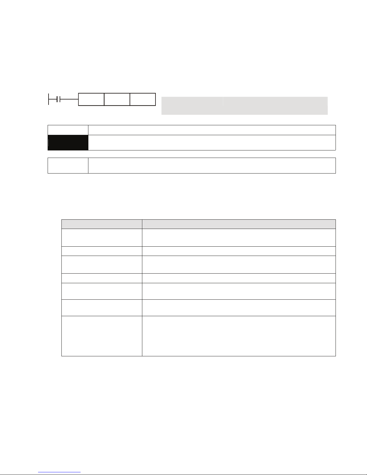
Appendix C Use of Basic Instructions|DOP-EXIO Series
C-8
Revision March, 2008, Doc. Name: 2007PDD23000014
using DCNT instruction is the same as using CNT instruction to enabling C0~C127.
2. When DCNT is Off, the counting will stop, but the existing present value in the counter will not be
cleared. To clear the present value and the contact, the user has to use the instruction RST C2XX.
Program Example:
Ladder diagram: Instruction code: Operation:
LD M0 Loading in contact A of M0
M0
C254DCNT
K1000
DCNT C254
K1000
Set value of counter C254 as K1,000
Mnemonic Functions
MC / MCR
Master Control Start / Reset
Operand N0~N7
Explanations:
1. MC is the main-control start instruction. When MC instruction is executed, the execution of
instructions between MC and MCR will not be interrupted. When MC instruction is Off, the actions
of the instructions between MC and MCR are:
Instruction type Explanation
General purpose timer
Present value = 0
Coil is Off, No action for the contact
Accumulative timer Coil is Off, present value and contact stay intact
Subroutine timer
Present value = 0
Coil is Off, No action for the contact
Counter Coil is Off, present value and contact stay intact
Coils driven by OUT
instruction
All Off
Devices driven by SET and
RST instructions
Stay intact
Application instructions
All disabled.
The FOR-NEXT nested loop will still execute back and forth for N
times.
Instructions between FOR-NEXT will act as the instructions between
MC and MCR.
2. MCR is the main-control end instruction that is placed in the end of the main-control program.
There should not be any contact instructions prior to MCR instruction.
3. MC-MCR main-control program instructions support the nested program structure (max. 8 layers)
and please use the instruction in the order N0 ~ N7.
Page 74
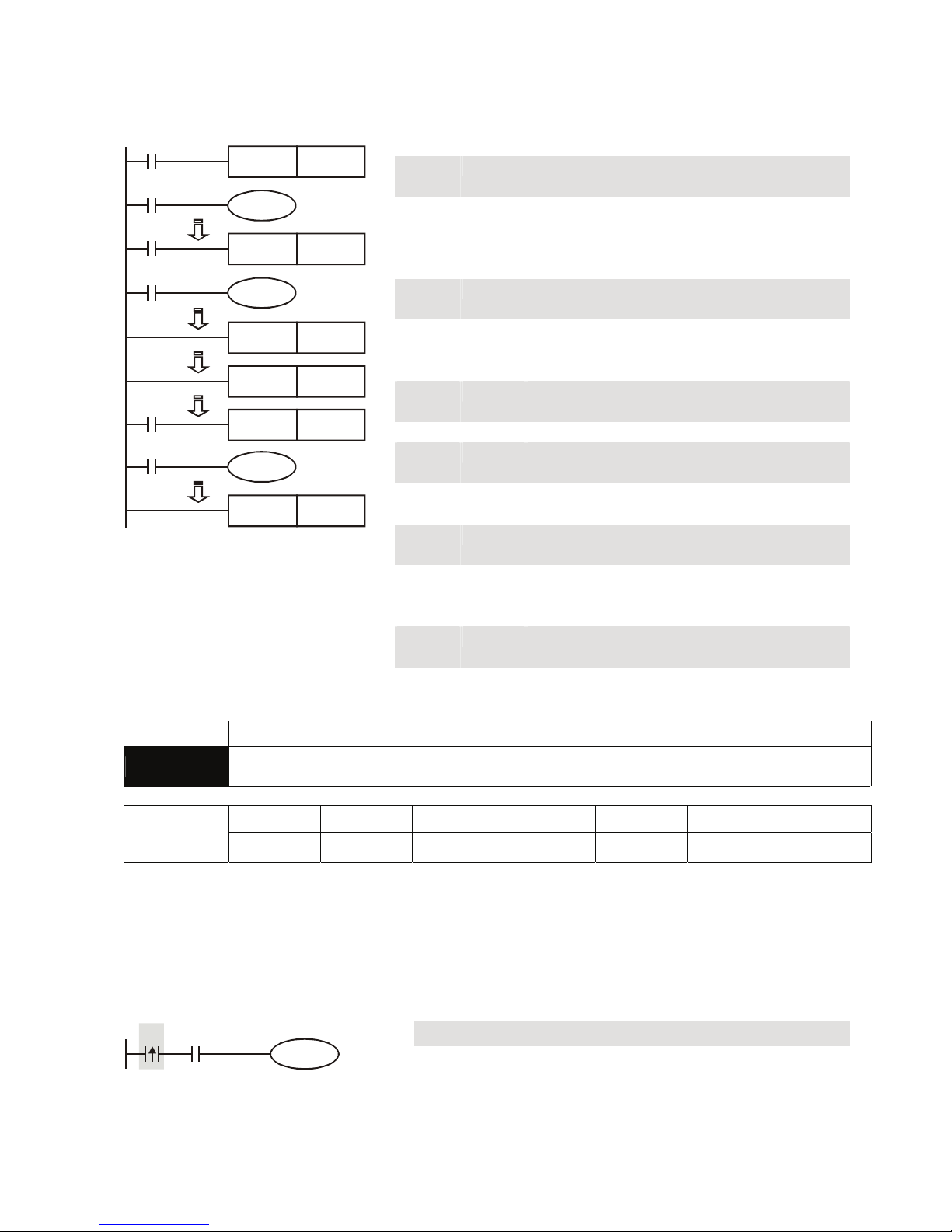
Appendix C Use of Basic Instructions|DOP-EXIO Series
Revision March, 2008, Doc. Name: 2007PDD23000014 C-9
Program Example:
Ladder diagram: Instruction code: Operation:
LD X0 Loading in A contact of X0
MC N0 Enabling N0 common series connection
contact
LD X1 Loading in A contact of X1
OUT Y0 Driving Y0 coil
:
LD X2 Loading in A contact of X2
MC N1 Enabling N1 common series connection
contact
LD X3 Loading in A contact of X3
OUT Y1 Driving Y1 coil
:
MCR N1 Disabling N1 common series connection
contact
:
MCR N0 Disabling N0 common series connection
contact
:
LD X10 Loading in A contact of X10
MC N0 Enabling N0 common series connection
contact
LD X11 Loading in A contact of X11
OUT Y10 Driving Y10 coil
:
MCR N0 Disabling N0 common series connection
contact
X0
Y0
MC N0
X1
X2
Y1
MC N1
X3
MCR N1
MCR N0
X10
MC N0
Y10
X11
MCR N0
Mnemonic Functions
LDP
Rising-edge Detection Operation
X0~X17 Y0~Y17 M0~M1279 S0~S127 T0~T127 C0~C254 D0~D599
Operand
9 9 9 9 9 9
-
Explanations:
The method of using LDP is the same as using LD, but the actions of the two instructions differ. LDP
saves the current content and store the detected status of rising-edge to the accumulative register.
Program Example:
Ladder diagram: Instruction code: Operation:
LDP X0
Starting X0 rising-edge detection
AND X1 Series connecting A contact of X1
X0 X1
Y1
OUT Y1 Driving Y1 coil
Page 75
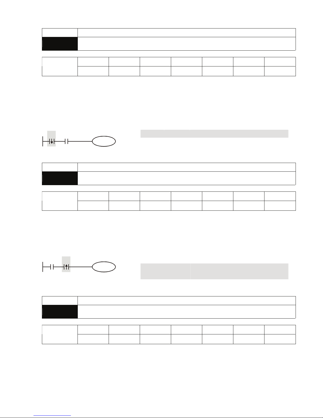
Appendix C Use of Basic Instructions|DOP-EXIO Series
C-10
Revision March, 2008, Doc. Name: 2007PDD23000014
Mnemonic Functions
LDF
Falling-edge Detection Operation
X0~X17 Y0~Y17 M0~M1279 S0~S127 T0~T127 C0~C254 D0~D599
Operand
9 9 9 9 9 9
-
Explanations:
The method of using LDF is the same as using LD, but the actions of the two instructions differ. LDF
saves the current content and store the detected status of falling-edge to the accumulative register.
Program Example:
Ladder diagram: Instruction code: Operation:
LDF X0 Starting X0 falling-edge detection
AND X1 Series connecting A contact of X1
X0 X1
Y1
OUT Y1 Driving Y1 coil
Mnemonic Functions
ANDP
Riding-edge Series Connection
X0~X17 Y0~Y17 M0~M1279 S0~S127 T0~T127 C0~C254 D0~D599
Operand
9 9 9 9 9 9
-
Explanations:
ANDP instruction is used in the series connection of the contacts’ rising-edge detection.
Program Example:
Ladder diagram: Instruction code: Operation:
LD X0 Loading in A contact of X0
ANDP X1 X1 rising-edge detection in series
connection
X1X0
Y1
OUT Y1 Driving Y1 coil
Mnemonic Functions
ANDF
Falling-edge Series Connection
X0~X17 Y0~Y17 M0~M1279 S0~S127 T0~T127 C0~C254 D0~D599
Operand
9 9 9 9 9 9
-
Explanations:
ANDF instruction is used in the series connection of the contacts’ falling-edge detection.
Page 76
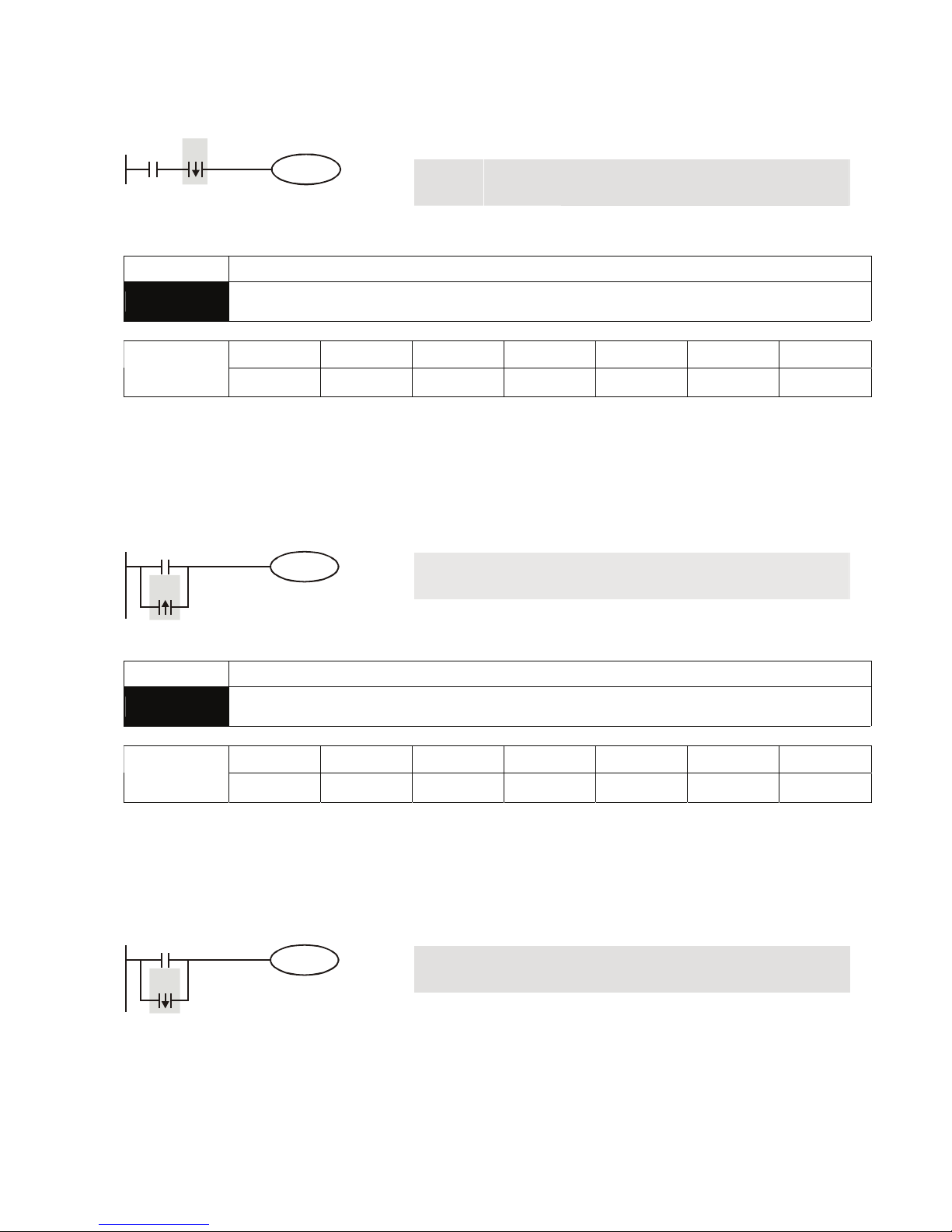
Appendix C Use of Basic Instructions|DOP-EXIO Series
Revision March, 2008, Doc. Name: 2007PDD23000014 C-11
Program Example:
Ladder diagram: Instruction code: Operation:
LD X0 Loading in A contact of X0
ANDF X1 X1 falling-edge detection in series
connection
X1X0
Y1
OUT Y1 Drive Y1 coil
Mnemonic Functions
ORP
Rising-edge Parallel Connection
X0~X17 Y0~Y17 M0~M1279 S0~S127 T0~T127 C0~C254 D0~D599
Operand
9 9 9 9 9 9
-
Explanations:
The ORP instructions are used in the parallel connection of the contact’s rising-edge detection.
Program Example:
Ladder diagram: Instruction code: Operation:
LD X0 Loading in A contact of X0
ORP X1 X1 rising-edge detection in parallel
connection
X0
X1
Y1
OUT Y1 Driving Y1 coil
Mnemonic Functions
ORF
Falling-edge Parallel Connection
X0~X17 Y0~Y17 M0~M1279 S0~S127 T0~T127 C0~C254 D0~D599
Operand
9 9 9 9 9 9
-
Explanations:
The ORF instructions are used in the parallel connection of the contact’s falling-edge detection.
Program Example:
Ladder diagram: Instruction code: Operation:
LD X0 Loading in A contact of X0
ORF X1 X1 falling-edge detection in parallel
connection
X0
X1
Y1
OUT Y1 Driving Y1 coil
Page 77
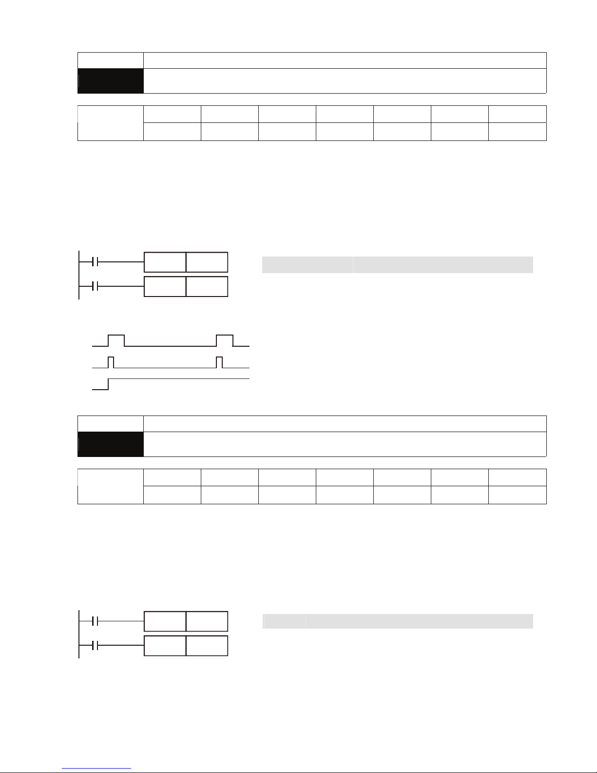
Appendix C Use of Basic Instructions|DOP-EXIO Series
C-12
Revision March, 2008, Doc. Name: 2007PDD23000014
Mnemonic Functions
PLS
Rising-edge Output
X0~X17 Y0~Y17 M0~M1279 S0~S127 T0~T127 C0~C254 D0~D599
Operand
-
9 9
- - - -
Explanations:
When X0 goes from Off to On (rising-edge trigger), PLS instruction will be executed and M0 will send
out pulses for once of 1 scan time.
Program Example:
Ladder diagram: Instruction code: Operation:
LD X0
Loading in A contact of X0
PLS M0
M0 rising-edge output
LD M0
Loading in contact A of M0
X0
M0
PLS
M0
Y0SET
Timing Diagram:
X0
M0
Y0
1 scan time
SET Y0
Y0 latched (On)
Mnemonic Functions
PLF
Falling-edge Output
X0~X17 Y0~Y17 M0~M1279 S0~S127 T0~T127 C0~C254 D0~D599
Operand
-
9 9
- - - -
Explanations:
When X0 goes from On to Off (falling-edge trigger), PLF instruction will be executed and M0 will send
out pulses for once of 1 scan time.
Program Example:
Ladder diagram: Instruction code: Operation:
LD X0 Loading in A contact of X0
PLF M0 M0 falling-edge output
LD M0 Loading in contact A of M0
X0
M0
PLF
M0
Y0SET
SET Y0 Y0 latched (On)
Page 78
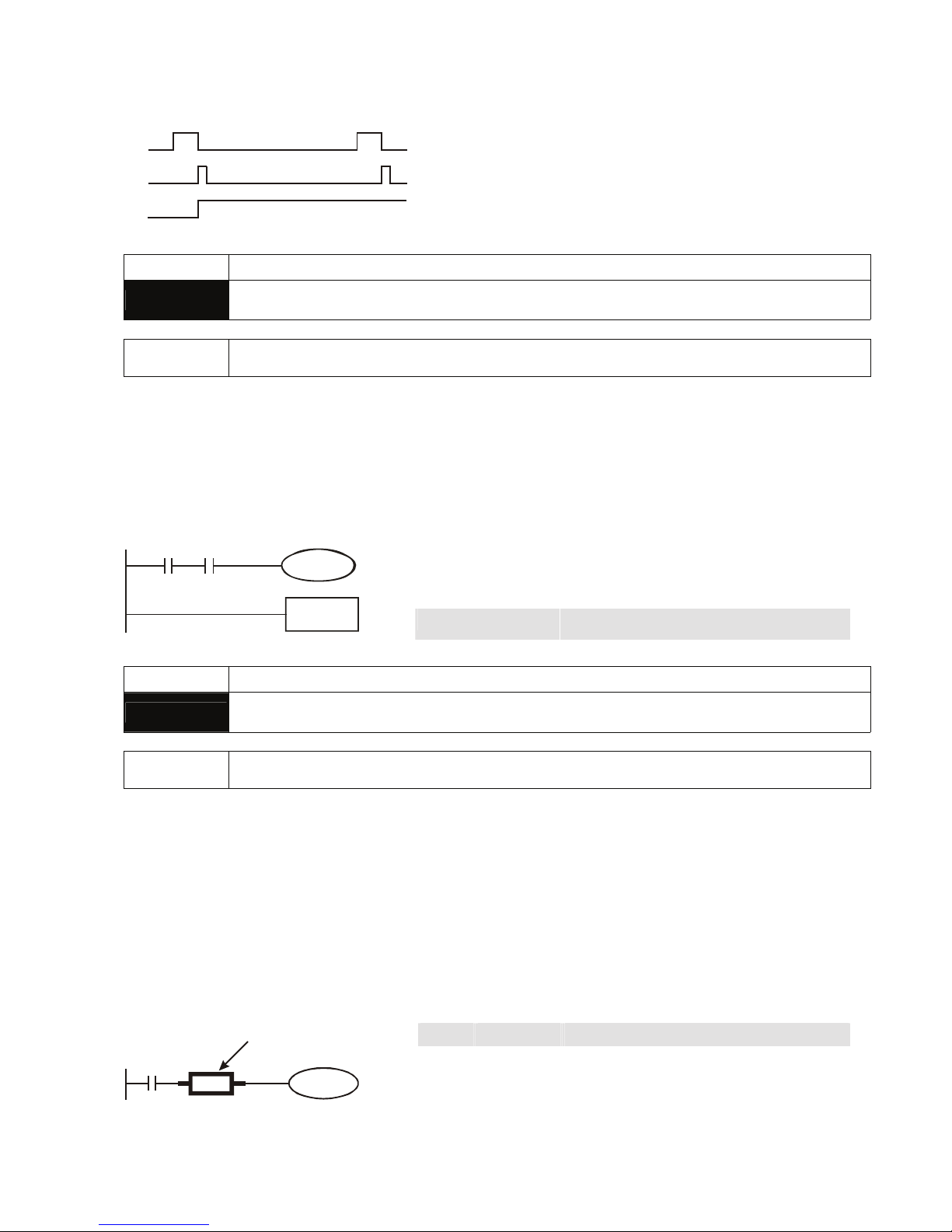
Appendix C Use of Basic Instructions|DOP-EXIO Series
Revision March, 2008, Doc. Name: 2007PDD23000014 C-13
Timing Diagram:
1 scan time
X0
M0
Y0
Mnemonic Functions
END
Program End
Operand None
Explanations:
END instruction has to be placed in the end of a ladder diagram or instruction program. DOP-EXIO
series will start to scan from address 0 to END instruction and return to address 0 to restart the scan.
Program Example:
Ladder diagram: Instruction code: Operation:
LD X0
Loading in B contact of X0
AND X1
Series connecting A contact of X1
OUT Y1
Driving Y1 coil
X0 X1
Y1
END
END
Program end
Mnemonic Functions
NOP
No Operation
Operand None
Explanations:
NOP instruction does not conduct any operations in the program; therefore, after the execution of NOP,
the existing logical operation result will be kept. If the user wants to delete a certain instruction without
altering the length of the program, the user can use NOP instruction. If the user wants to delete a
certain instruction temporarily, the user can also use NOP instruction.
Program Example:
Ladder diagram: Instruction code: Operation:
LD X0 Loading in B contact of X0
NOP No operation
X0
Y1
NOP
NOP instruction will be
omitted in the ladder diagram
OUT Y1 Driving Y1 coil
Page 79
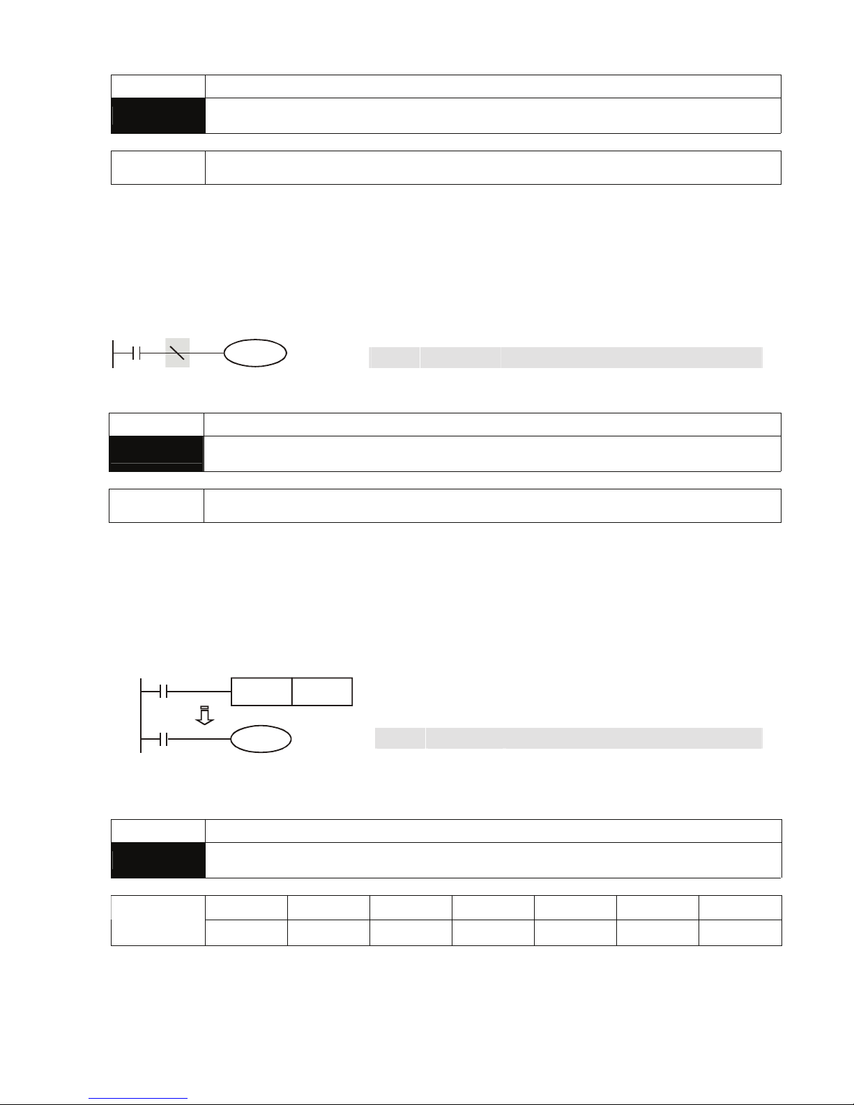
Appendix C Use of Basic Instructions|DOP-EXIO Series
C-14
Revision March, 2008, Doc. Name: 2007PDD23000014
Mnemonic Functions
INV
Inverting Operation
Operand None
Explanations:
The logical operation result before INV instruction will be inverted and stored in the accumulative
register.
Program Example:
Ladder diagram: Instruction code: Operation:
LD X0 Loading in A contact of X0
INV Inverting the operation result
X0
Y1
OUT Y1 Driving Y1 coil
Mnemonic Functions
P
Pointer
Operand P0~P63
Explanations:
Pointer P is used in 00 CJ and 01 CALL instructions. The use of P does not need to start from No. 0,
and the No. of P cannot be repeated; otherwise, unexpected errors may occur.
Program Example:
Ladder diagram: Instruction code: Operation:
LD X0 Loading in A contact of X0
CJ P10 From instruction CJ to P10
:
P10 Pointer P10
LD X1 Loading in A contact of X1
X0
Y1
CJ P10
X1
P10
OUT Y1 Driving Y1 coil
Mnemonic Functions
STL
Step Transition Ladder Start Command
X0~X17 Y0~Y17 M0~M1279 S0~S127 T0~T127 C0~C254 D0~D599
Operand
- - -
9
- - -
Explanations:
STL Sn constructs a step. When STL instruction appears in the program, the program will enter a step
ladder diagram status controlled by steps. The initial status has to start from S0 ~ S9. RET instruction
Page 80
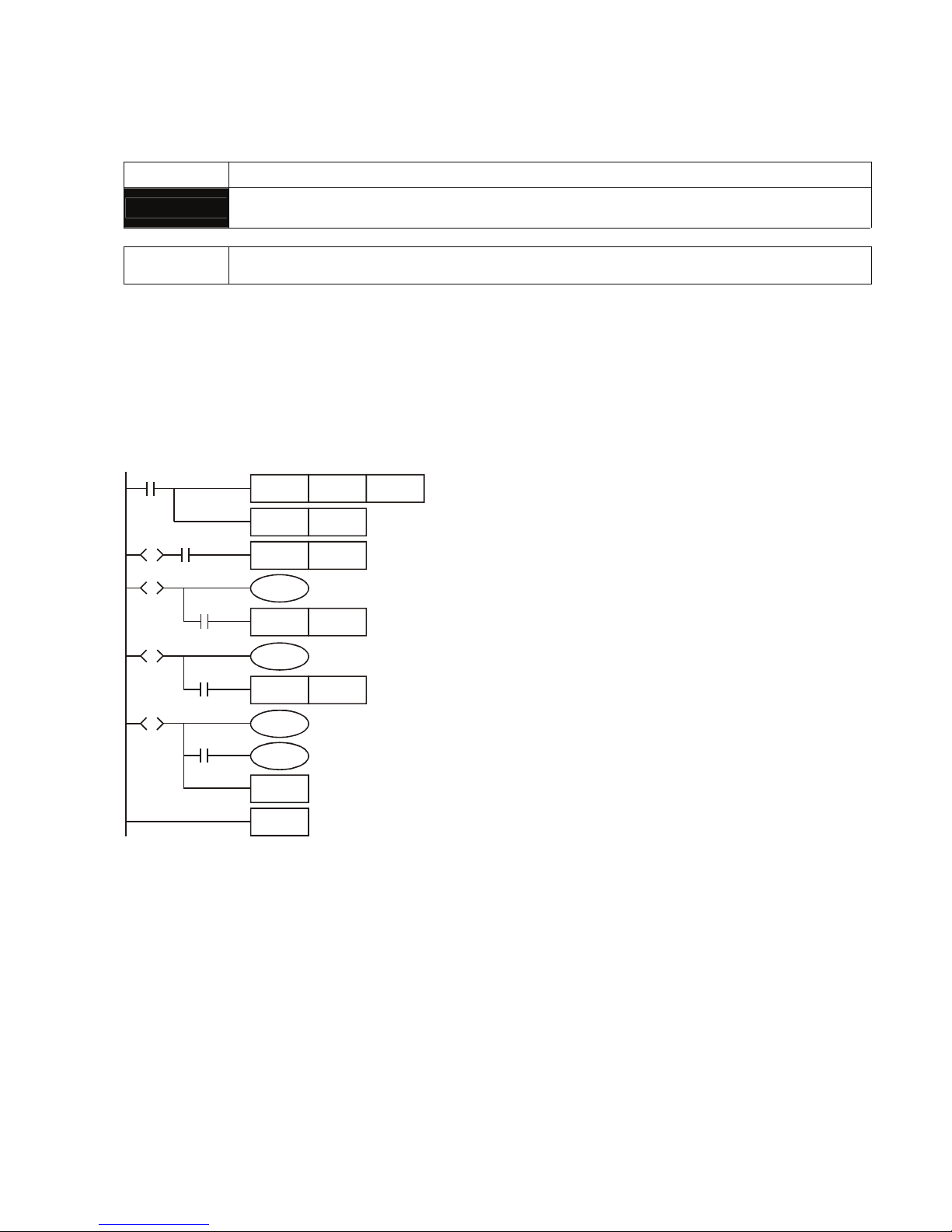
Appendix C Use of Basic Instructions|DOP-EXIO Series
Revision March, 2008, Doc. Name: 2007PDD23000014 C-15
indicates the end of a step ladder diagram starting from S0 ~ S9 and the bus returns to a normal ladder
diagram instruction. The No. of S cannot be repeated.
Mnemonic Functions
RET
Step Transition Ladder Return Command
Operand None
Explanations:
RET indicates the end of a step. There has to be a RET instruction in the end of a series of steps. One
EXIO program can be written in maximum 10 steps (S0 ~ S9) and every step should end with a RET.
Program Example:
Ladder diagram:
M1002
ZRST S0 S127
SET S0
SET S20
Y0
SET S30
Y1
SET S40
Y2
S0
RET
END
X0S0
S
S20
S
X1
S30
S
X2
S40
S
X3
Page 81

Appendix C Use of Basic Instructions|DOP-EXIO Series
C-16
Revision March, 2008, Doc. Name: 2007PDD23000014
This page intentionally left blank.
Page 82
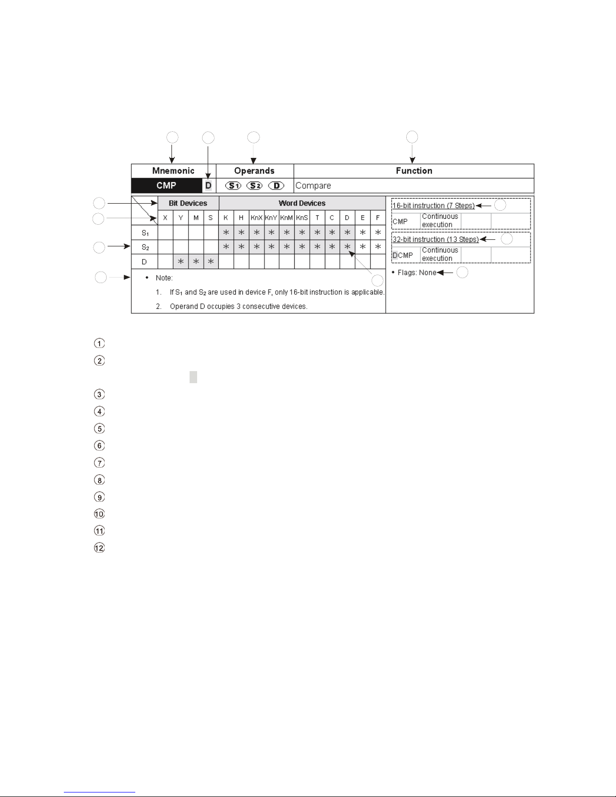
Appendix D Use of Application Instructions|DOP-EXIO Series
Revision March, 2008, Doc. Name: 2007PDD23000014 D-1
Appendix D Use of Application Instructions
Format of an application instruction:
1
12
11
10
9
3
4
5
6
7
8
2
Mnemonic of an application instruction.
Indication of if there is a 16-bit or 32-bit instruction. If there is a 32-bit instruction, the column will
be marked with “D”.
Operands
Function of the application instruction
Steps occupied by the 16-bit execution instruction
Steps occupied by the 32-bit execution instruction
Related flags for the application instruction
Column marked with * and in grey refers to E, F index register modification is applicable.
Note
Column marked with * is the device applicable for the operand
Device name
Device type
Page 83
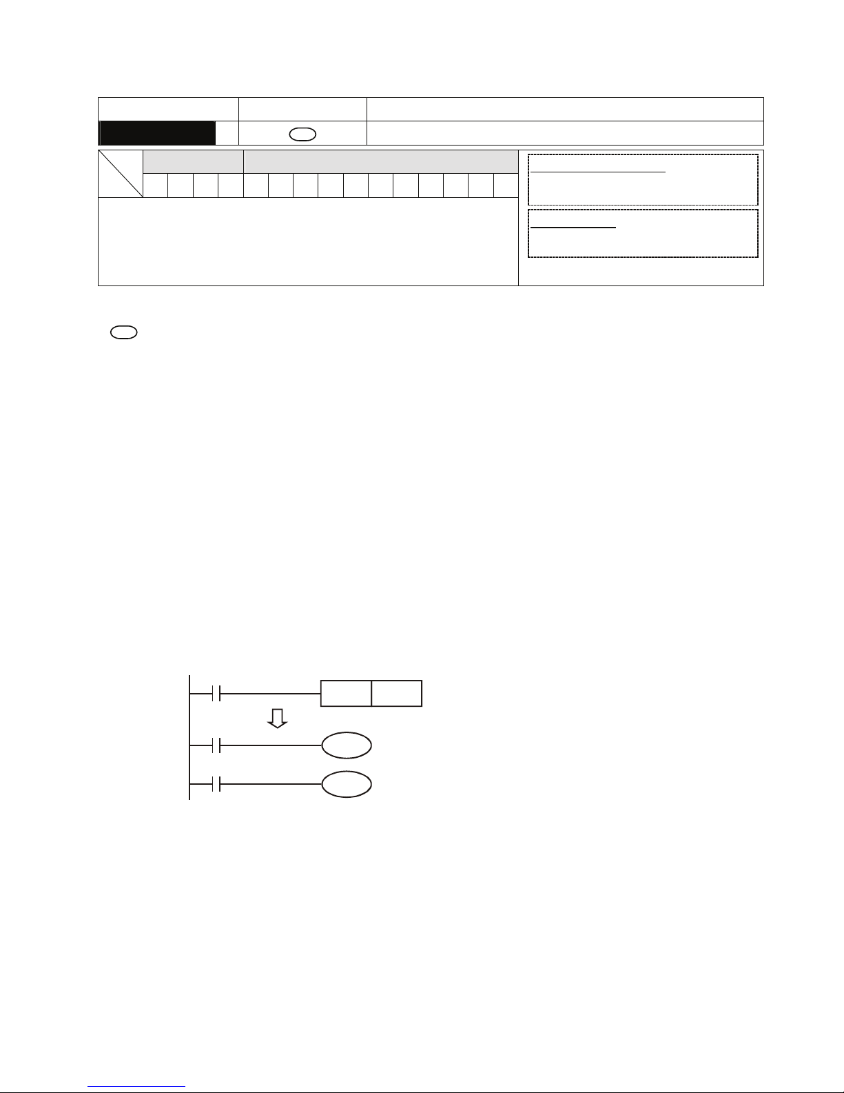
Appendix D Use of Application Instructions|DOP-EXIO Series
D-2
Revision March, 2008, Doc. Name: 2007PDD23000014
Mnemonic Operands Function
CJ
S
Conditional Jump
Bit Devices Word Devices
X Y M S K H KnX KnY KnM KnS T C D E F
y Note:
1. Operand S can designate P.
2. P can be modified by index register E, F.
16-bit instruction (3 Steps)
CJ
Continuous
execution
32-bit instruction
- - - -
y Flags: None
Operands:
S
: The destination pointer of conditional jump
Explanations:
1. When the user does not wish a particular part of DOP-EXIO program in order to shorten the scan
time and execute dual outputs, CJ instruction or CJP instruction can be adopted.
2. When the program designated by pointer P is prior to CJ instruction, WDT timeout will occur and
DOP-EXIO will stop running. Please use it carefully.
3. CJ instruction can designate the same pointer P repeatedly. However, CJ and CALL cannot
designate the same pointer P; otherwise an error will occur.
Program Example 1:
1. When X0 = On, the program automatically jumps from address 0 to N (the designated label P1)
and keeps its execution. The addresses between 0 and N will not be executed.
2. When X0 = Off, as an ordinary program, the program keeps on executing from address 0. CJ
instruction will not be executed at this time.
X0
X1
X2
CJ P1
Y1
Y2
0
NP1
P***
()
CJ instruction
Program Example 2:
1. CJ instruction can be used in the following 5 conditions between MC and MCR instructions.
a)
Without MC ~ MCR.
b) From without MC to within MC. Valid in the loop P1 as shown in the figure below.
c) In the same level N, inside of MC~MCR.
d) From within MC to without MCR.
e) Jumping from this MC ~ MCR to another MC ~ MCR
Page 84
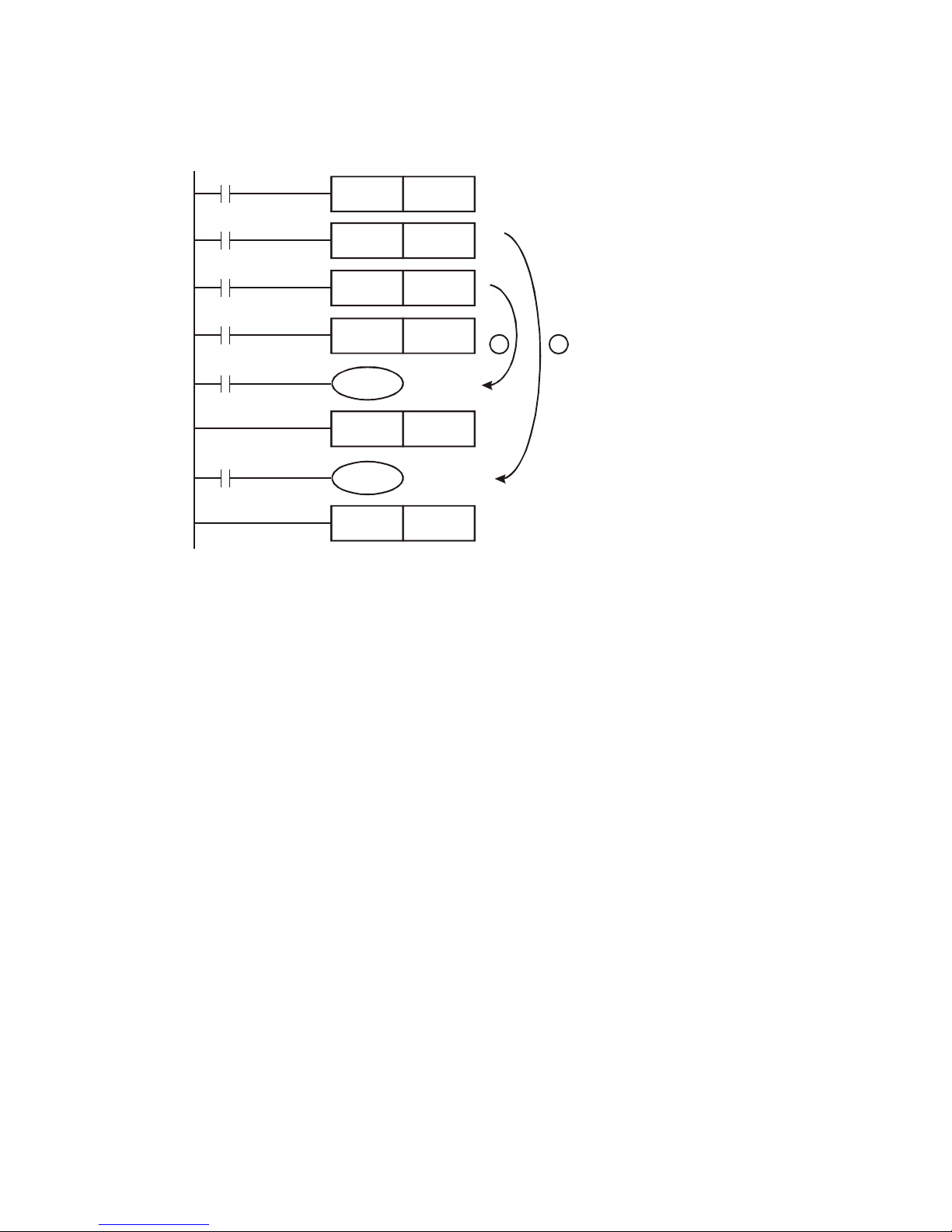
Appendix D Use of Application Instructions|DOP-EXIO Series
Revision March, 2008, Doc. Name: 2007PDD23000014 D-3
2. When CJ instruction is used between MC and MCR, it can only be applied without MC ~ MCR or
in the same N layer of MC ~ MCR. Jumping from this MC ~ MCR to another MC ~ MCR will result
in errors, i.e. a) and c) as stated above can ensure correct actions; others will cause errors.
X0
MC N0
X2
X3
X1
M1000
M1000
P1
P0
CJ
CJ
MC
N1
N1
N0
P1
P0
Y1
Y0
MCR
MCR
Program Example 3:
1. The status of each device when executing CJ instruction:
¾ The method of using this CJ instruction is similar to the method of using goto instruction of
C-language. When executing CJ instruction, the status of each device will not be changed.
¾ When the timers are driven and encounter the execution of CJ instruction, the timing will
resume. After the timing target is reached, the output contact of the timer will be On.
¾ The counter will stop counting (This is because the counter is activated to count via the
software).
¾ All the instructions which have encounterd the execution of CJ instruction will not be
activated.
2. Y1 is a dual output. When M0 = Off, Y1 is controlled by M1. When M0 = On, Y1 is controlled by
M12.
Page 85
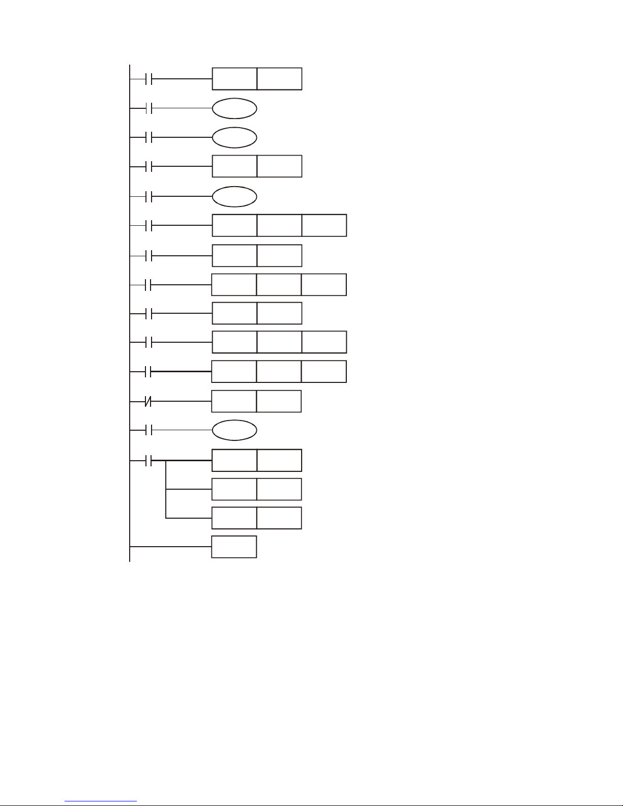
Appendix D Use of Application Instructions|DOP-EXIO Series
D-4
Revision March, 2008, Doc. Name: 2007PDD23000014
CJ P0
M0
M1
M2
M17
M3
M4
M5
M6
M7
M10
M11
M0
M12
M13
END
RST
RST
RST T127
C0
D0
Y1
CJ P0
CJ P63
S1
TMR
T0
K10
TMR
RST
RST
CNT
MOV
T127
T127
C0
C0
D0K3
K20
Y1
M20
K1000
P0
P63
Page 86
Appendix D Use of Application Instructions|DOP-EXIO Series
Revision March, 2008, Doc. Name: 2007PDD23000014 D-5
Mnemonic Operands Function
CALL
S
Call Subroutine
Bit Devices Word Devices
X Y M S K H KnX KnY KnM KnS T C D E F
y Note:
1. Operand S can designate P.
2. P can be modified by index register E, F.
16-bit instruction (3 Steps)
CALL
Continuous
execution
32-bit instruction
- - - -
y Flags: None
Operands:
S
: The pointer of call subroutine.
Explanations:
1. Edit the subroutine designated by the pointer after FEND instruction.
2. The number of pointer P, when used by CALL, cannot be the same as the number designated by
CJ instruction.
3. If only CALL instruction is in use, it can call subroutines of the same pointer number with no limit
on times.
4. Subroutine can be nested for 5 levels including the initial CALL instruction. (If entering the sixth
level, the subroutine won’t be executed.)
Page 87
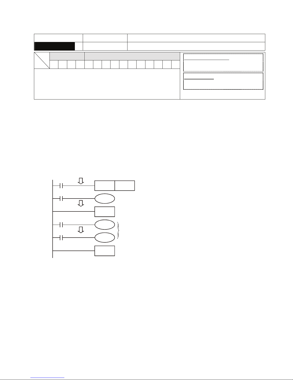
Appendix D Use of Application Instructions|DOP-EXIO Series
D-6
Revision March, 2008, Doc. Name: 2007PDD23000014
Mnemonic Operands Function
SRET
None Subroutine Return
Bit Devices Word Devices
X Y M S K H KnX KnY KnM KnS T C D E F
y Note:
1. No operand.
2. No contact to drive the instruction is required.
16-bit instruction (1 Step)
SRET
Continuous
execution
- -
32-bit instruction
- - - -
y Flags: None
Explanations:
1. This instruction denotes the end of the subroutine program.
2. The subroutine will return to main program by SRET after the termination of subroutine and
execute the sequence program located at the next step to the CALL instruction.
Program Example 1:
When X0 = On, CALL instruction is executed and the program jumps to the subroutine designated by
P2. When SRET instruction is executed, the program returns to address 24 and continues its
execution.
X0
X1
CALL P2
Y1
20
P***
24
FEND
SRET
P2
Y0
Y0
Subroutine P2
subroutine return
call subroutine P***
Program Example 2:
1. When X10 goes from Off to On, its rising-edge trigger executes CALL P10 instruction and the
program jumps to the subroutine designated by P10.
2. When X11 is On, CALL P11 is executed and the program jumps to the subroutine designated by
P11.
3. When X12 is On, CALL P12 is executed and the program jumps to the subroutine designated by
P12.
4. When X13 is On, CALL P13 is executed and the program jumps to the subroutine designated by
P13.
Page 88
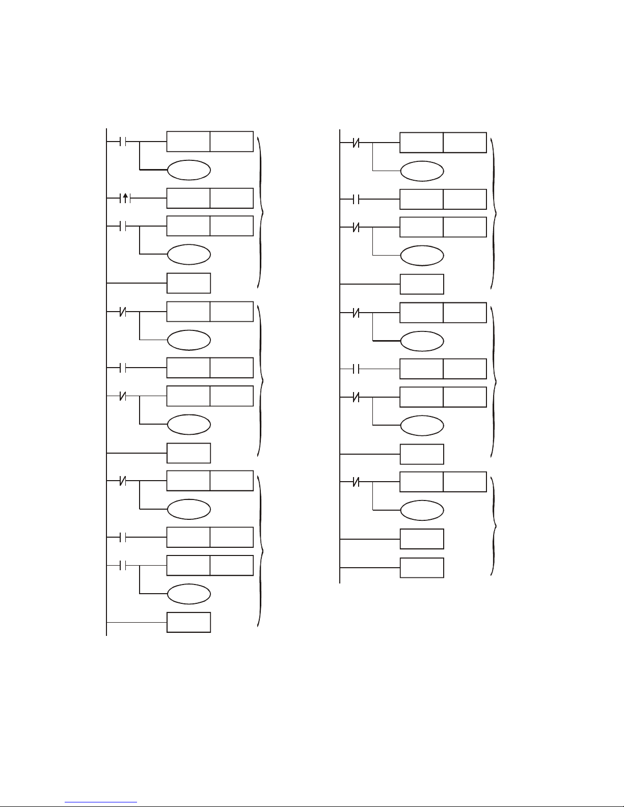
Appendix D Use of Application Instructions|DOP-EXIO Series
Revision March, 2008, Doc. Name: 2007PDD23000014 D-7
5. When X14 is On, CALL P14 is executed and the program jumps to the subroutine designated by
P14. When SRET is executed, the program returns to the previous P** subroutine and continues
its execution.
6. After SRET instruction is executed in P10 subroutine, returning to the main program.
X0
X10
INC
D0
Y0
CALL P10
X0
INC
D1
Y1
FEND
INC D10
X2
P10
Y4
X2
X11
CALL P11
INC D11
Y5
SRET
INC D20
X2
P11
Y6
X12
CALL P12
X2
INC D21
Y7
SRET
X2
X13
X2
X2
X2
X14
X2
P13
P14
P12
INC
D30
Y10
CALL P13
INC
D31
Y11
SRET
INC D40
Y12
CALL P14
INC D41
Y13
SRET
INC D50
Y14
SRET
END
Main
Program
Main
Program
subroutine
subroutine
subroutine
subroutine
subroutine
Page 89
Appendix D Use of Application Instructions|DOP-EXIO Series
D-8
Revision March, 2008, Doc. Name: 2007PDD23000014
Mnemonic Operands Function
FEND
None The End of The Main Program (First End)
Bit Devices Word Devices
X Y M S K H KnX KnY KnM KnS T C D E F
y Note:
1. No operand.
2. No contact to drive the instruction is required.
16-bit instruction (1 Step)
FEND
Continuous
execution
- -
32-bit instruction
- - - -
y Flags: None
Explanations:
1. This instruction denotes the end of the main program. It has the same function as that of END
instruction when being executed by DOP-EXIO series.
2. CALL must be written after FEND instruction and add SRET instruction in the end of its
subroutine. Interruption program has to be written after FEND instruction and IRET must be
added in the end of the service program.
3. If several FEND instructions are in use, place the subroutine and interruption service programs
between the final FEND and END instruction.
4. After CALL instruction is executed, executing FEND before SRET will result in errors in the
program.
5. After FOR instruction is executed, executing FEND before NEXT will result in errors in the
program.
Page 90
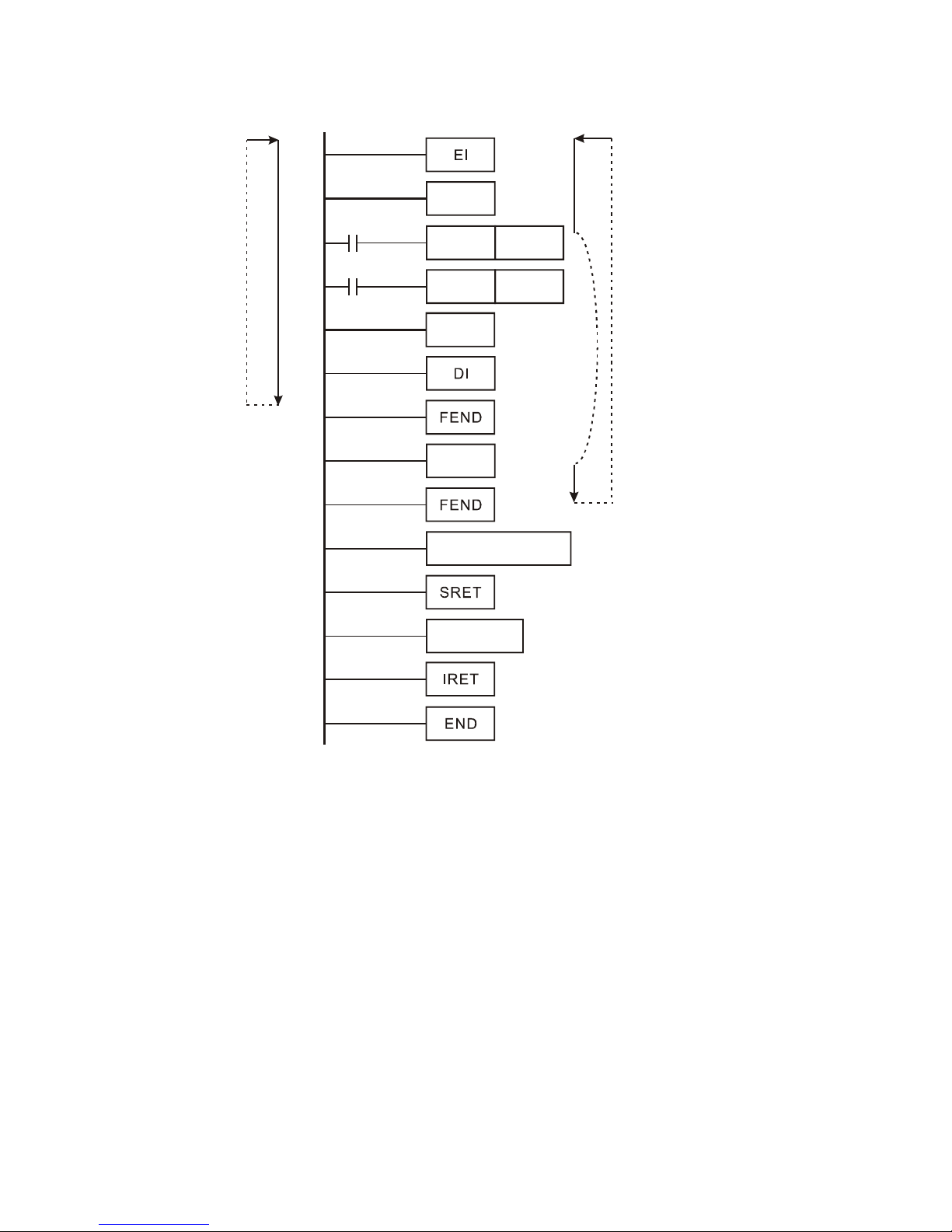
Appendix D Use of Application Instructions|DOP-EXIO Series
Revision March, 2008, Doc. Name: 2007PDD23000014 D-9
CJ Instruction Program Flow:
X1
CALL P63
P0
P63
CJ P0
I301
X0
0
The program flow
when X0=off,
X1=off
main
program
main
program
main
program
The program flow when X=On
and the program jumps to P0.
Interruption
subroutine
CALL instruction
subroutine
Page 91
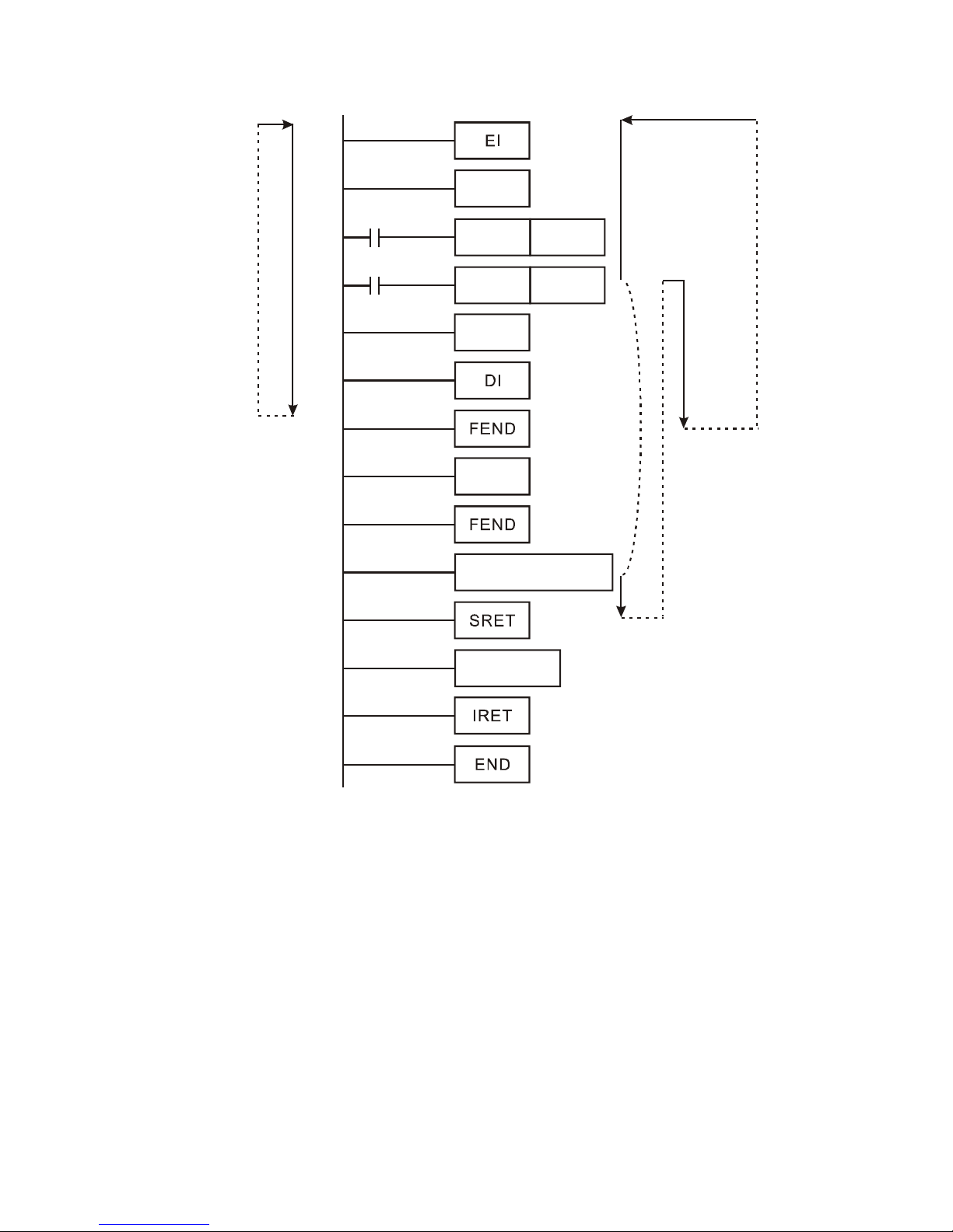
Appendix D Use of Application Instructions|DOP-EXIO Series
D-10
Revision March, 2008, Doc. Name: 2007PDD23000014
CALL Instruction Program Flow:
X1
CALL P63
P0
P63
CJ P0
I301
X0
0
The program flow
when X0=off,
X1=off
main
program
main
program
main
program
The program flow
when X0=Off,
X1=On.
Interruption
subroutine
CALL instruction
subroutine
Page 92
Appendix D Use of Application Instructions|DOP-EXIO Series
Revision March, 2008, Doc. Name: 2007PDD23000014 D-11
Mnemonic Operands Function
FOR
S
Start of a FOR-NEXT Loop
Bit Devices Word Devices
X Y M S K H KnX KnY KnM KnS T C D E F
S
y Note:
1. No contact to drive the instruction is required.
16-bit instruction (3 Steps)
FOR
Continuous
execution
- -
32-bit instruction
- - - -
y Flags: None
Operands:
S
: The number of repeated nested loops
Mnemonic Operands Function
NEXT
None End of a FOR-NEXT Loop
Bit Devices Word Devices
X Y M S K H KnX KnY KnM KnS T C D E F
y Note:
1. No operand.
2. No contact to drive the instruction is required.
16-bit instruction (1 Step)
NEXT
Continuous
execution
- -
32-bit instruction
- - - -
y Flags: None
Explanations:
1. FOR instruction indicates FOR ~ NEXT loops executing back and forth N times before escaping
for the next execution.
2. N = K1 ~ K32,767. N is regarded as K1 when N ≤ 1.
3. When FOR~NEXT loops are not executed, the user can use the CJ instruction to escape the
loops.
4. Error will occur when
a) NEXT instruction is before FOR instruction.
b) FOR instruction exists but NEXT instruction does not exist.
c) There is NEXT instruction after FEND or END instruction.
d) The number of instructions between FOR ~ NEXT differs.
5. FOR~NEXT loops can be nested for maximum five levels. Be careful that if there are too many
loops, the increased PLC scan time may cause timeout of watchdog timer and error. Users can
use WDT instruction to modify this problem.
Program Example 1:
After program A has been executed for 3 times, it will resume its execution after NEXT instruction.
Program B will be executed for 4 times whenever program A is executed once. Therefore, program B
will be executed 3 × 4 = 12 times in total.
Page 93
Appendix D Use of Application Instructions|DOP-EXIO Series
D-12
Revision March, 2008, Doc. Name: 2007PDD23000014
FOR K3
FOR K4
NEXT
NEXT
A
B
Program Example 2:
When X7 = Off, DOP-EXIO series will execute the program between FOR ~ NEXT. When X7 = On, CJ
instruction jumps to P6 and avoids executing the programs between FOR ~ NEXT.
X7
M0
M0
P6
MOV
FOR
MOV
D0
D0
K3
K0
Y10
INC
MEXT
X10
D0
D1
CJ
P6
Program Example 3:
When the programs between FOR ~ NEXT are not to be executed, the user can adopt CJ instruction
for a jumping. When the most inner FOR ~ NEXT loop is in the status of X1 = On, CJ instruction
executes jumping to P0 and skips the execution on P0.
Page 94
Appendix D Use of Application Instructions|DOP-EXIO Series
Revision March, 2008, Doc. Name: 2007PDD23000014 D-13
X0
TMR T0 K10
P0
FOR K4X100
X0
INC D0
K2
X0
D1
K3
X0
D2
K4
X0
WDT
D3
X1
CJ
P0
FOR
K5
X0
INC D4
NEXT
NEXT
NEXT
NEXT
NEXT
END
FOR
INC
FOR
INC
FOR
INC
Page 95
Appendix D Use of Application Instructions|DOP-EXIO Series
D-14
Revision March, 2008, Doc. Name: 2007PDD23000014
Mnemonic Operands Function
CMP D
S
1
S
2
D
Compare
Bit Devices Word Devices
X Y M S K H KnX KnY KnM KnS T C D E F
S
1
S
2
D
y Note:
1. If S1 and S2 are used in device F, only 16-bit instruction is applicable.
2. Operand D occupies 3 consecutive devices.
16-bit instruction (7 Steps)
CMP
Continuous
execution
32-bit instruction (13 Steps)
DCMP
Continuous
execution
y Flags: None
Operands:
S
1
: Comparison Value 1
S
2
: Comparison Value 2
D
: Comparison result
Explanations:
1. The contents in S
1
and S2 are compared and the result will be stored in D.
2. The two comparison values are compared algebraically and the two values are signed binary
values. When b15 = 1 in 16-bit instruction or b31 = 1 in 32-bit instruction, the comparison will
regard the value as negative binary values.
Program Example:
1. Designate device Y0, and operand D automatically occupies Y0, Y1, and Y2.
2. When X10 = On, CMP instruction will be executed and one of Y0, Y1, and Y2 will be On. When
X10 = Off, CMP instruction will not be executed and Y0, Y1, and Y2 remain their status before
X10 = Off.
3. If the user needs to obtain a comparison result with ≥ ≤, and ≠, make a series parallel connection
between Y0 ~ Y2.
X10
Y0
Y1
Y2
CMP
K10
D10
Y0
If K10>D10, Y0 = On
If K10=D10, Y1 = On
If K10<D10, Y2= On
4. To clear the comparison result, use RST or ZRST instruction.
Page 96
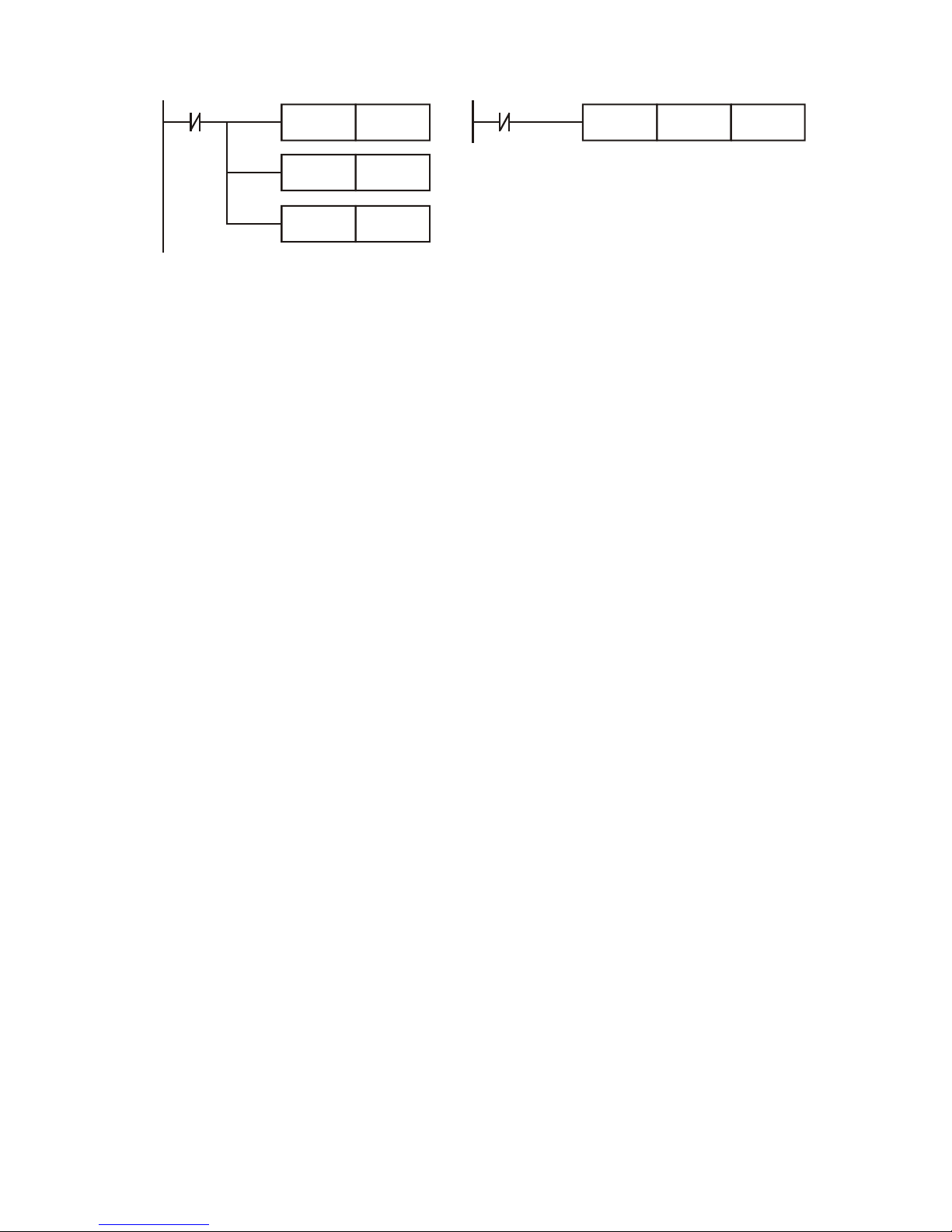
Appendix D Use of Application Instructions|DOP-EXIO Series
Revision March, 2008, Doc. Name: 2007PDD23000014 D-15
X10
RST M0
RST
RST
M1
M2
X10
ZRST M0 M2
Page 97
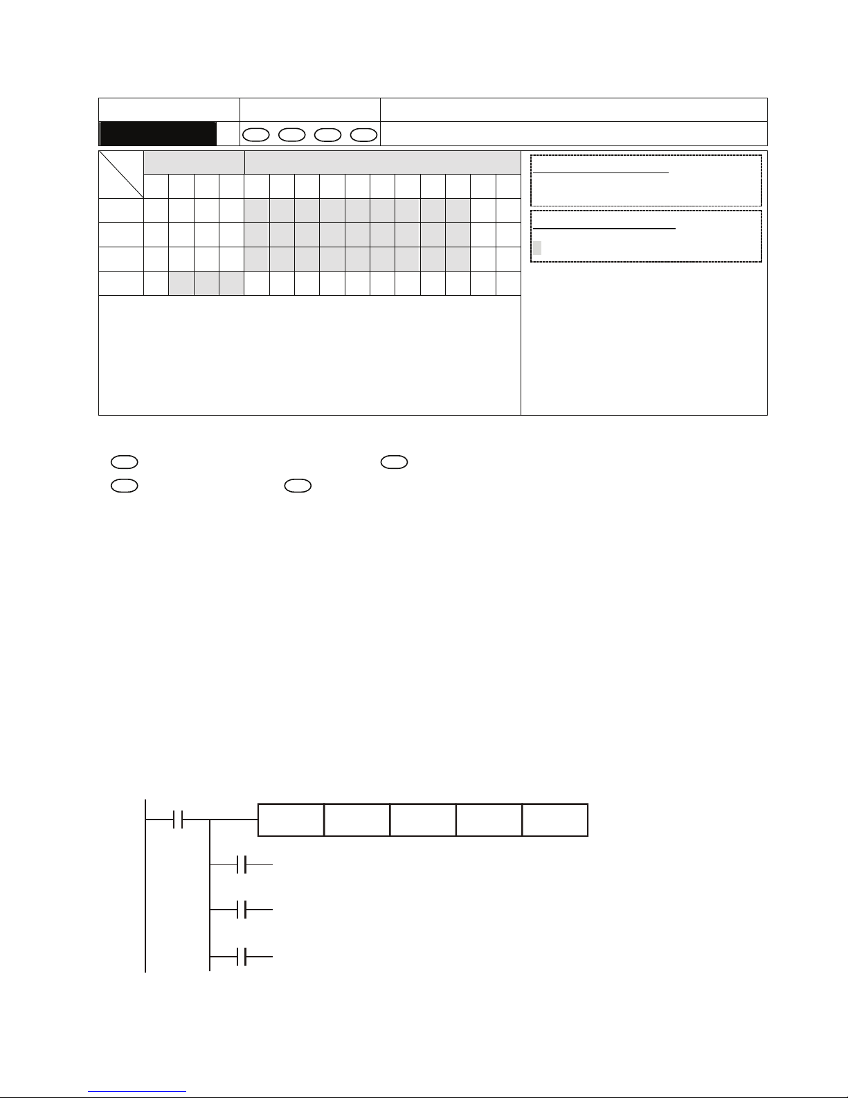
Appendix D Use of Application Instructions|DOP-EXIO Series
D-16
Revision March, 2008, Doc. Name: 2007PDD23000014
Mnemonic Operands Function
ZCP
S
1
S
2
S D
Zone Compare
Bit Devices Word Devices
X Y M S K H KnX KnY KnM KnS T C D E F
S
1
S
2
S
D
y Note:
1. If S1, S2 and S are used in device F, only 16-bit instruction is
applicable.
2. The content in S1 should be smaller than the content in S2.
3. Operand D occupies 3 consecutive devices.
16-bit instruction (9 Steps)
ZCP
Continuous
execution
32-bit instruction (17 Steps)
DZCP
Continuous
execution
y Flags: None
Operands:
S
1
: Lower bound of zone comparison
S
2
: Upper bound of zone comparison
S
: Comparison value
D
: Comparison result
Explanations:
1. S is compared with its S
1
, S2 and the result is stored in D.
2. When S
1
> S2, the instruction performs comparison by using S1 as the lower/upper bound.
3. The two comparison values are compared algebraically and the two values are signed binary
values. When b15 = 1 in 16-bit instruction or b31 = 1 in 32-bit instruction, the comparison will
regard the value as negative binary values.
Program Example:
1. Designate device M0, and operand D automatically occupies M0, M1 and M2.
2. When X0 = On, ZCP instruction will be executed and one of M0, M1, and M2 will be On. When X0
= Off, ZCP instruction will not be executed and M0, M1, and M2 remain their status before X0 =
Off.
X0
M0
M1
M2
ZCP
If C10 < K10, M0 = On
If K10 < C10 < K1 00, M1 = On
If C10 > K100, M2 = On
X0
K10 C10 M0K100
==
3. To clear the comparison result, use RST or ZRST instruction.
Page 98
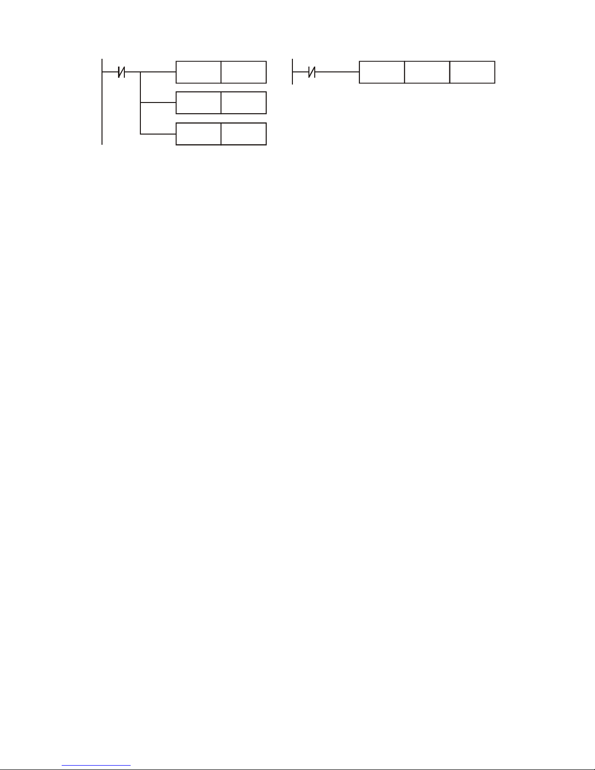
Appendix D Use of Application Instructions|DOP-EXIO Series
Revision March, 2008, Doc. Name: 2007PDD23000014 D-17
X0
RST M0
RST
RST
M1
M2
X0
ZRST M0 M2
Page 99
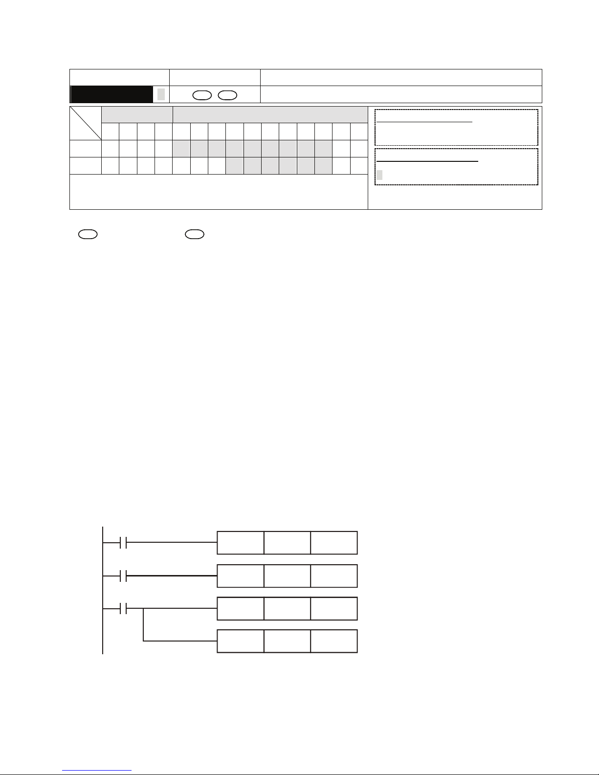
Appendix D Use of Application Instructions|DOP-EXIO Series
D-18
Revision March, 2008, Doc. Name: 2007PDD23000014
Mnemonic Operands Function
MOV D
S D
Move
Bit Devices Word Devices
X Y M S K H KnX KnY KnM KnS T C D E F
S
D
y Note:
1. If S, and D are used in device F, only 16-bit instruction is applicable.
16-bit instruction (5 Steps)
MOV
Continuous
execution
32-bit instruction (9 Steps)
DMOV
Continuous
execution
y Flags: None
Operands:
S
: Source of data
D
: Destination of data
Explanations:
1. When this instruction is executed, the content of S will be moved directly to D. When this
instruction is not executed, the content of D remains unchanged.
2. If the operation result refers to a 32-bit output, (i.e. application instruction MUL and so on), and
the user needs to move the present value in the 32-bit high-speed counter, DMOV instruction has
to be adopted.
Program Example:
1. MOV instruction has to be adopted in the moving of 16-bit data.
a) When X0 = Off, the content in D10 will remain unchanged. If X0 = On, the value K10 will be
moved to D10 data register.
b) When X1 = Off, the content in D10 will remain unchanged. If X1 = On, the present value T0
will be moved to D10 data register.
2. DMOV instruction has to be adopted in the moving of 32-bit data.
When X2 = Off, the content in (D31, D30) and (D41, D40) will remain unchanged. If X2 = On, the
present value of (D21, D20) will be sent to (D31, D30) data register. Meanwhile, the present
value of C235 will be moved to (D41, D40) data register.
X0
X1
X2
MOV K10 D0
MOV T0 D10
DMOV D20 D30
DMOV C235 D40
Page 100
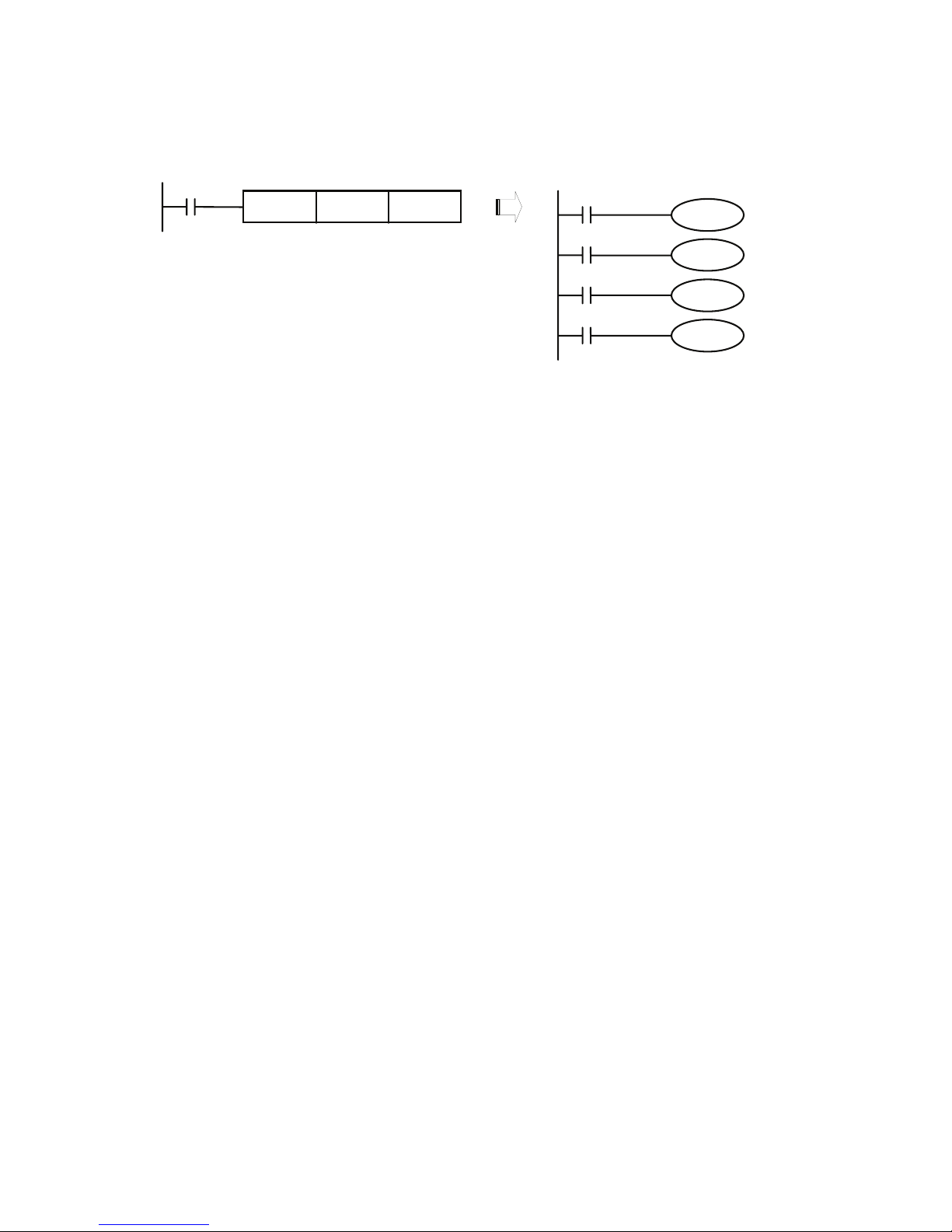
Appendix D Use of Application Instructions|DOP-EXIO Series
Revision March, 2008, Doc. Name: 2007PDD23000014 D-19
3. Move bit data:
When the program is driven, the data of X10~X13 is moved to the Y10~Y13. Please refer to the
figure below. The left program has the same function as the right.
M1000
MOV K1Y10
X10
Y10
X11
Y11
X12
Y12
X13
Y13
K1X10
 Loading...