

Datasheet EUP7201-1.5/2.8UIR1, EUP7201-1.5/2.8VIR1, EUP7201-1.8/2.6UIR1, EUP7201-1.8/2.6VIR1, EUP7201-1.8/2.8JIR1 Datasheet (Eutech) [ru]
...Page 1

EUP7201
Dual ,Low-Noise,150mA LDO Regulator
DESCRIPTION
The EUP7201 is highly accurate, Dual, low noise, CMOS
LDO voltage regulator. Performance features include low
output noise, high ripple rejection ratio, low dropout and
very fast turn-on times.
The EUP7201 is also fully compatible with low ESR
ceramic capacitors, reducing cost and improving output
stability. This high level of output stability is maintained
even during frequent load fluctuations, due to the excellent
transient response performance and high PSRR achieved
across a broad range of frequencies.
The EN function allows the output of each regulator to be
turned off independently, resulting in greatly reduced
power consumption. The EUP7201 is available in the
SOT23-6 , TDFN-6 and USP-6 package.
FEATURES
z Up to 150mA Output Current (Each LDO)
z Dual Shutdown Pins Control Each Output
z 124μV
z Current Limiting and Thermal Protection
z Short Circuit Protection
z 100mV Dropout at 100mA Load
z Current Limiting Protection
z Available in SOT23-6 ,TDFN-6 and USP-6 Package
z RoHS Compliant and 100% Lead (Pb)-Free
Low Noise Output
RMS
APPLICATIONS
z Cellular Phones
z Camera, Video Recorders
z PDAs
z Hand-held Equipment
T ypical Application Circuit
Figure 1.
DS7201 Ver 1.5 Oct. 2007
1
Page 2
EUP7201
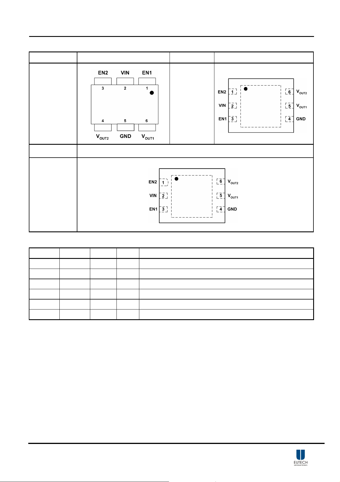
Pin Configurations
Package Type Pin Configurations Package Type Pin Configurations
SOT23-6
Package Type Pin Configurations
TDFN-6
USP-6
Pin Description
PIN SOT23-6 TDFN-6 USP-6 DESCRIPTION
EN1 1 3 3 ON/OFF Control V
VIN 2 2 2 Supply Input
EN2 3 1 1 ON/OFF Control V
V
4 6 6 Channel 2 Output Voltage
OUT2
GND 5 4 4 Ground
V
6 5 5 Channel1 Output Voltage
OUT1
OUT1
OUT2
Note: If EN1 and EN2 are both low, both regulators and the reference turn off.
DS7201 Ver 1.5 Oct. 2007
2
Page 3
EUP7201
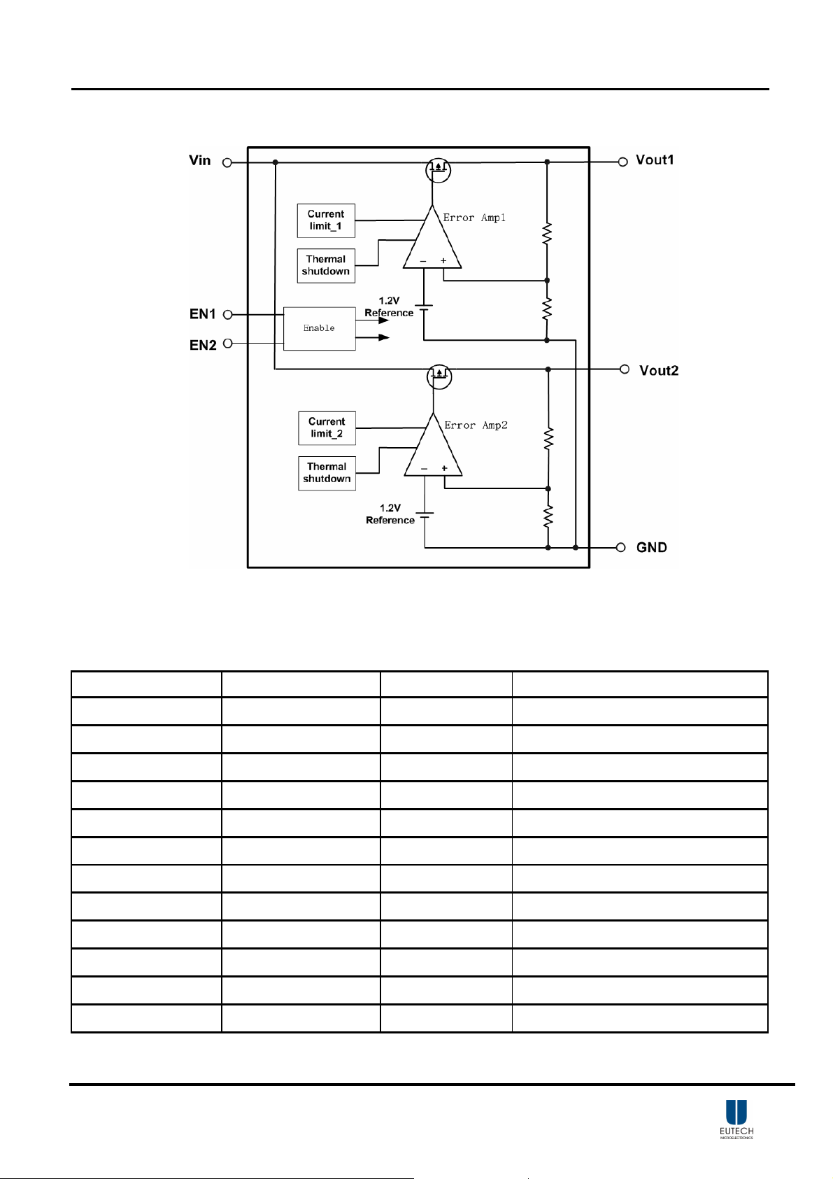
Block Diagram
Figure 2.
Ordering Information
Order Number Package Type Marking Operating Temperatur e range
□ □ □ □
EUP7201-1.5/2.8VIR1 SOT23-6
EUP7201-1.8/2.8VIR1 SOT23-6
EUP7201-1.8/2.6VIR1 SOT23-6
EUP7201-1.8/3.3VIR1 SOT23-6
EUP7201-2.5/2.8VIR1 SOT23-6
EUP7201-2.8/1.2VIR1 SOT23-6
EUP7201-2.8/2.8VIR1 SOT23-6
N C
N A
□ □ □ □
N U
□ □ □ □
N H
□ □ □ □
N D
□ □ □ □
N P
□ □ □ □
N M
□ □ □ □
-40 °C to 85°C
-40 °C to 85°C
-40 °C to 85°C
-40 °C to 85°C
-40 °C to 85°C
-40 °C to 85°C
-40 °C to 85°C
N K
EUP7201-2.8/3.0VIR1 SOT23-6
EUP7201-2.8/3.3VIR1 SOT23-6
EUP7201-3.0/3.0VIR1 SOT23-6
EUP7201-3.0/3.3VIR1 SOT23-6
EUP7201-3.3/3.3VIR1 SOT23-6
□ □ □ □
N L
□ □ □ □
N N
□ □ □ □
N T
□ □ □ □
N J
□ □ □ □
-40 °C to 85°C
-40 °C to 85°C
-40 °C to 85°C
-40 °C to 85°C
-40 °C to 85°C
DS7201 Ver 1.5 Oct. 2007
3
Page 4
EUP7201
Ordering Information (Continued)
Order Number Package Type Marking Operating Temperatur e range
EUP7201-1.8/2.8JIR1 TDFN-6
EUP7201-1.5/2.8UIR1 USP-6
EUP7201-1.8/2.8UIR1 USP-6
EUP7201-1.8/2.6UIR1 USP-6
EUP7201-1.8/3.3UIR1 USP-6
EUP7201-2.5/2.8UIR1 USP-6
EUP7201-2.8/1.2UIR1 USP-6
EUP7201-2.8/2.8UIR1 USP-6
EUP7201-2.8/3.0UIR1 USP-6
EUP7201-2.8/3.3UIR1 USP-6
EUP7201-3.0/3.0UIR1 USP-6
EUP7201-3.0/3.3UIR1 USP-6
EUP7201-3.3/3.3UIR1 USP-6
xxxxx
7201A
xxx
NC
xxx
NA
xxx
NU
xxx
NH
xxx
ND
xxx
NP
xxx
NM
xxx
NK
xxx
NL
xxx
NN
xxx
NT
xxx
NJ
-40 °C to 85°C
-40 °C to 85°C
-40 °C to 85°C
-40 °C to 85°C
-40 °C to 85°C
-40 °C to 85°C
-40 °C to 85°C
-40 °C to 85°C
-40 °C to 85°C
-40 °C to 85°C
-40 °C to 85°C
-40 °C to 85°C
-40 °C to 85°C
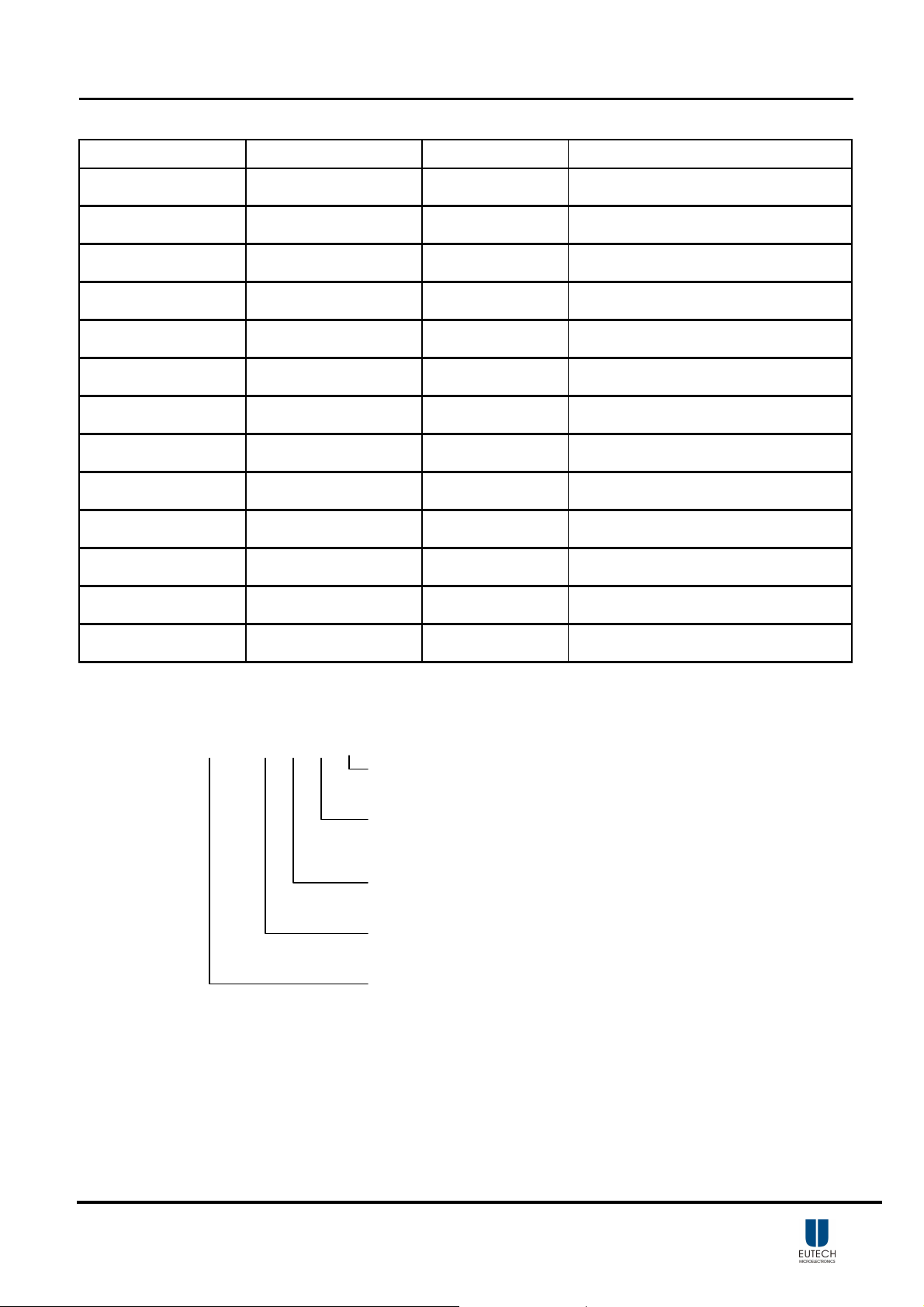
EUP7201-
□□/□□ □ □ □ □
Lead Free Code
1: Lead Free 0: Lead
Packing
R: Tape & Reel
Operating temperature range
I: Industry Standard
Package Type
V: SOT23 J: TDFN U:USP
Output Voltage Option
* EUP7201-VOUT1/VOUT2 VIRI
DS7201 Ver 1.5 Oct. 2007
4
Page 5
EUP7201
Absolute Maximum Ratings
▓ Supply Input Voltage --------------------------------------------------------------------------------------- 6V
▓ Power Dissipation, P
SOT23-6 ------------------------------------------------------------------------------------------------------ 0.4W
▓ Package Thermal Resistance
SOT23-6, θ
▓ Lead Temperature (Soldering,10 sec .) -------------------------------------------------------------------- 260°C
▓ Storage Temperature Range -------------------------------------------------------------------------------- -65°C to 150°C
▓ ESD Rating
------------------------------------------------------------------------------------------------- 250°C/W
JA
@ T
D
=25℃
A
HBM ---------------------------------------------------------------------------------------------------------- 2kV
Recommended Operating Conditions
▓ Supply Input Voltage ----------------------------------------------------------------------------------------- 2.5V to 5.5V
▓ Enable Input Voltage ----------------------------------------------------------------------------------------- 0V to 5.5V
▓ Junction Temperature Range ------------------------------------------------------------------------------- -40°C to 125°C
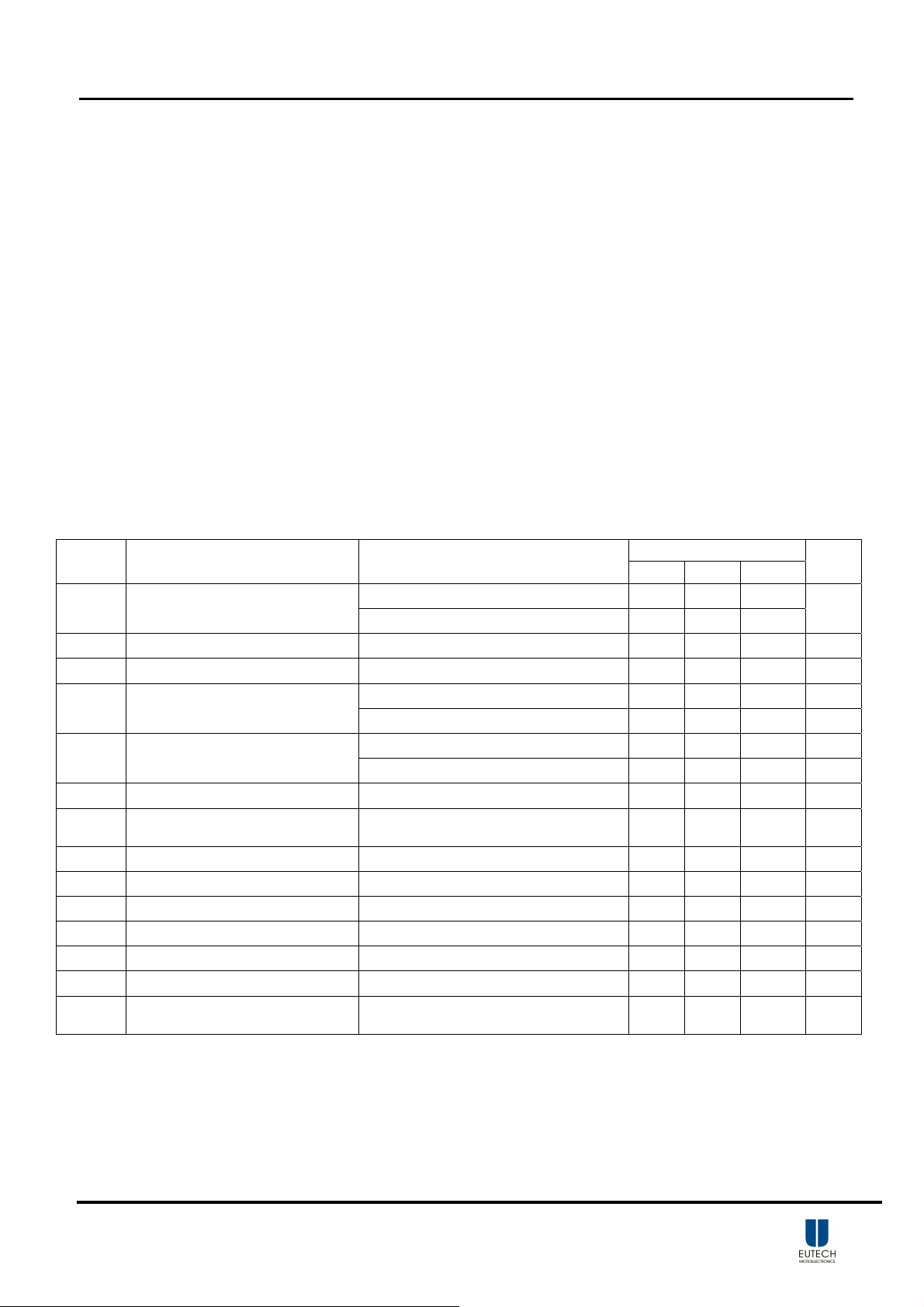
Electrical Characteristics
VIN= (V
Unless otherwise noted
Symbol Parameter Conditions
V
Output voltage
OUT
I
Maximum Output Current Continuous ,TA=-40°C~85°C. 150 mA
MAX
I
Current Limit Output Grounded (Steady State) 180 300 mA
LIM
IG Quiescent Current
V
DROP
ΔV
OUT
ΔV
LINE
VIH EN Input High Threshold VIN=2.5V to 5.5V, TA=-40°C~85°C. 1.6 V
VIL EN Input Low Threshold VIN=2.5V to 5.5V, TA=-40°C~85°C. 0.4 V
ISD EN Input Bias Current EN=GND or VIN 0.1 µA
I
Shutdown Supply Current EN1=EN2=GND 0.01 1 µA
GSD
TSD Thermal Shutdown Temperature 155
ΔT
SD
PSRR Ripple Rejection Rate
+0.5V) or VIN=2.5V whichever is greater, CIN =C
OUT
=1µF , EN1=EN2= V
OUT
. TA=25°C.
IN
EUP7201
Min Typ Max.
IL=30mA -2 2
=30mA, TA=-40°C~85°C. -3 3
I
L
No Load (Both LDOs) 110 180 µA
=150mA (Both LDOs) 260 µA
I
OUT
I
=30mA 30 mV
Dropout Voltage
Load Regulation 1mA< I
Line Regulation
Thermal Shutdown Hysteresis 15
OUT
I
=100mA, TA=-40°C~85°C. 80 220 mV
OUT
< 150mA 13 60 mV
OUT
V
IN=VOUT
I
OUT
V
IN
I
OUT
+0.5V to 5.5V
=1mA
=(V
+1V) DC+0.5V p-p AC
OUT
=1mA, f=1kHz
0.02 0.2 %/V
60 dB
Unit
%
℃
℃
DS7201 Ver 1.5 Oct. 2007
5
Page 6

EUP7201
Typical Operating Characteristics
DS7201 Ver 1.5 Oct. 2007
6
Page 7

EUP7201
DS7201 Ver 1.5 Oct. 2007
7
Page 8

EUP7201
DS7201 Ver 1.5 Oct. 2007
8
Page 9

EUP7201
DS7201 Ver 1.5 Oct. 2007
9
Page 10

EUP7201
≈
Application Note
External Capacitors
Capacitor Characteristics
Like any low-dropout regulator, the EUP7201 requires
external capacitors for
regulator stability. The EUP7201 is
specifically designed for portable applications requiring
minimum board space and smallest components. These
capacitors must be correctly selected for good
performance.
Input Capacitor
An input capacitance of
1µF is required between the
≈
EUP7201 input pin and ground (the amount of the
capacitance may be increased without limit).
This capacitor must be located a distance of not more than
1cm from the input pin and returned to a clean analog
ground. Any good quality ceramic, tantalum, or film
capacitor may be used at the input.
If a tantalum capacitor is used at the input, it must be
guaranteed by the manufacturer to have a
surge current
rating sufficient for the application.
There are no requirements for the ESR on the input
capacitor, but tolerance and temperature coefficient must
be considered when selecting the capacitor to
capacitance will be
1µF over the entire operating
≈
ensure the
temperature range.
Output Capacitor
The EUP7201 is designed specifically to work with very
small ceramic output capacitors. A ceramic capacitor
(temperature characteristics X7R, X5R, Z5U, or Y5V) in 1
to 22µF range with 5mΩ to
500mΩ ESR range is suitable
in the EUP7201 application circuit.
The output capacitor must meet the requirement for
minimum amount of capacitance and also have an ESR
(Equivalent Series Resistance) value which is within a
stable range (5mΩ to 500mΩ)
No-Load Stability
The EUP7201 will remain stable and in regulation with no
external load. This is specially important in CMOS RAM
keep-alive applications.
The EUP7201 is designed to work with ceramic
capacitors on the output to take advantage of the benefits
they offer: for capacitance values in the range of 1µF to
4.7µF range, ceramic capacitors are the smallest, least
expensive and have the lowest ESR values (which makes
them best for eliminating high frequency noise). The
ESR of a typical 1µF ceramic capacitor is in the range of
20mΩ to 40mΩ, which easily meets the ESR requirement
for stability by the EUP7201.
The ceramic capacitor’s capacitance can vary with
temperature. The capacitor type X7R, which operates
over a temperature range of -55°C to +125°C, will only
vary the capacitance to within ±15%. Most large value
ceramic capacitors (
2.2µF) are manufactured with Z5U
or Y5V temperature characteristics. Their capacitance
can drop by more than 50% as the temperature goes from
25°C to 85°C. Therefore,
X7R is recommended over Z5U
and Y5V in applications where the ambient temperature
will change significantly above or below 25°C.
On/Off Input Operation
The EUP7201 is turned off by pulling the
V
EN
pin low,
and turned on by pulling it high. If this feature is not used,
the V
output on at all time.
signal source used to drive the V
pin should be tied to VIN to keep the regulator
EN
To assure proper operation, the
input must be able
EN
to swing above and below the specified turn-on/off
voltage thresholds listed in the Electrical Characteristics
section under V
and VIH.
IL
DS7201 Ver 1.5 Oct. 2007
10
Page 11

EUP7201
Packaging Information
SOT23-6
SYMBOLS MILLIMETERS INCHES
MIN. MAX. MIN. MAX.
A - 1.45 - 0.057
A1 0.00 0.15 0.000 0.006
b 0.30 0.50 0.012 0.020
D 2.90 0.114
E1 1.60 0.063
e 0.95 0.037
E 2.60 3.00 0.102 0.118
L 0.30 0.60 0.012 0.024
DS7201 Ver 1.5 Oct. 2007
11
Page 12

EUP7201
TDFN-6
DETAIL A
SYMBOLS
DS7201 Ver 1.5 Oct. 2007
A 0.70 0.80 0.028 0.031
A1 0.00 0.05 0.000 0.002
b 0.30 0.50 0.012 0.020
D 2.90 3.10 0.114 0.122
D1 2.30 0.090
E 2.90 3.10 0.114 0.122
E1 1.50 0.059
e 0.95 0.037
L 0.38 0.58 0.015 0.023
MILLIMETERS INCHES
MIN. MAX. MIN. MAX.
12
Page 13

EUP7201
USP-6
SYMBOLS
A 0.70 0.80 0.028 0.031
A1 0.00 0.05 0.000 0.002
b 0.10 0.30 0.004 0.012
b1 0.20 0.40 0.008 0.016
D 1.70 1.90 0.067 0.075
D1 1.50 0.059
E 1.90 2.10 0.075 0.083
E1 0.90 0.035
e 0.50 0.020
L 0.15 0.35 0.006 0.014
MILLIMETERS INCHES
MIN. MAX. MIN. MAX.
DS7201 Ver 1.5 Oct. 2007
13
Page 14

 Loading...