

Page 1
05194
Only One Name Means ProTek’Tion™
APPLICATIONS
✔ Ethernet - 10/100/1000 Base T
✔ CAN Bus
✔ Cellular Phones
✔ Audio/Video Inputs
✔ Personal Digital Assistant (PDA)
✔ E1/T1 & E3/T3
IEC COMPATIBILITY (EN61000-4)
✔ 61000-4-2 (ESD): Air - 15kV, Contact - 8kV
✔ 61000-4-4 (EFT): 40A - 5/50ns
FEATURES
✔ ESD Protection > 25 kilovolts
✔ 100 Watts Peak Pulse Power per Line (tp = 8/20µs)
✔ Protects Two (2) Bidirectional Lines
✔ Bidirectional Configuration
✔ Low Leakage Current < 1.0µA
✔ ✔
✔
LOW CAPACITANCE: 6pF PER LINE
✔ ✔
ESOT24LCC-2
LOW CAPACITANCE TVS ARRAY
SOT-23
MECHANICAL CHARACTERISTICS
✔ Molded JEDEC SOT-23
✔ Weight 14 milligrams (Approximate)
✔ Flammability rating UL 94V-0
✔ 8mm Tape and Reel Per EIA Standard 481
✔ Device Marking: Marking Code
PIN CONFIGURATION
1
2
3
105194.R0 8/03 www.protekdevices.com
Page 2
DEVICE CHARACTERISTICS
MAXIMUM RATINGS @ 25°C Unless Otherwise Specified
ESOT24LCC-2
PARAMETER
Peak Pulse Power (tp = 8/20µs) - See Figure 1
Peak Pulse Current (tp = 8/20µs)
Operating Temperature
Storage Temperature
SYMBOL VALUE
P
PP
I
PP
T
J
T
STG
100
2
-55°C to 150°C
ELECTRICAL CHARACTERISTICS PER LINE @ 25°C Unless Otherwise Specified
PA RT
NUMBER
(See Note 1 & 2)
DEVICE
MARKING
CODE
RATED
STAND-OFF
VOLTAGE
V
WM
VOLTS
ESOT24LCC-2 24L 24.0 26.6
Note 1: Test between pins 1 to 3 and 2 to 3 in both directions.
Note 2: Per IEC 61000-4-2, ESD ± 25kV.
MINIMUM
BREAKDOWN
VOLTAGE
@ 1mA
V
(BR)
VOLTS
MAXIMUM
LEAKAGE
CURRENT
@V
WM
I
D
µA
16
UNITS
Watts
A
°C-55°C to 150°C
°C
TYPICAL
CAPACITANCE
PER LINE
@0V, 1MHz
C
pF
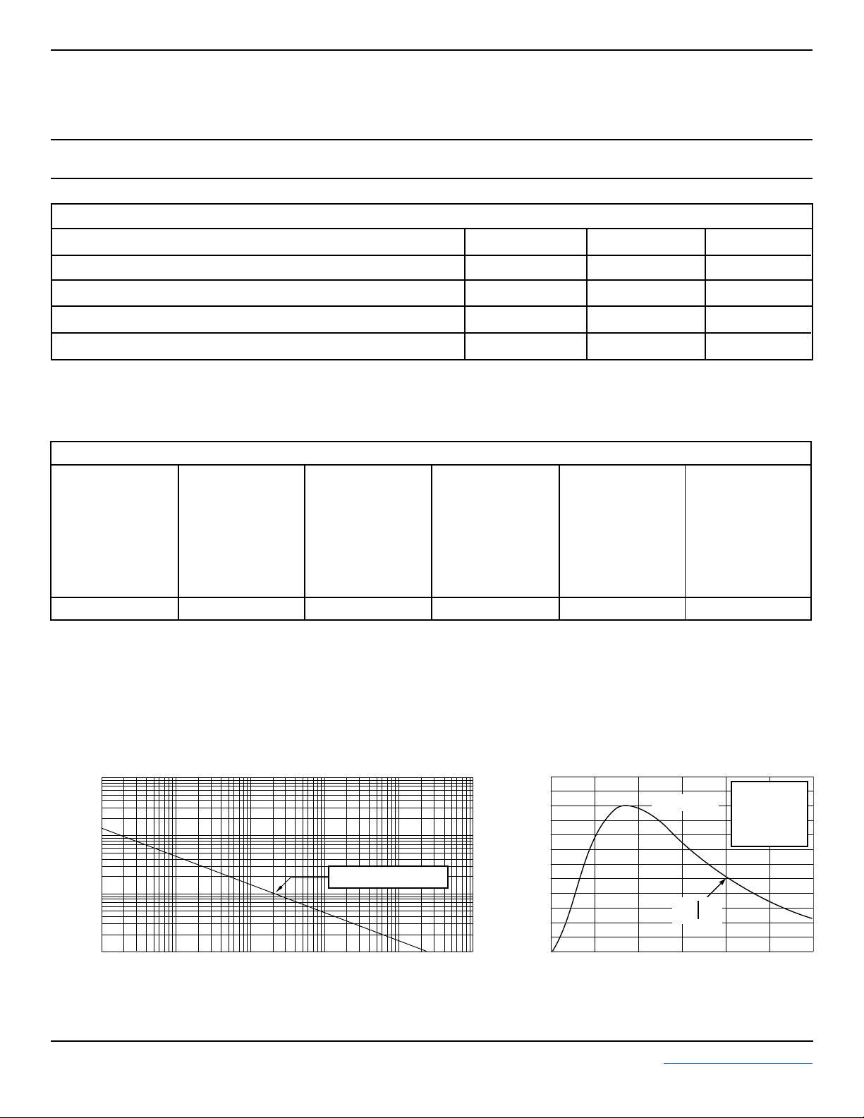
PEAK PULSE POWER VS PULSE TIME
FIGURE 1
10,000
1,000
100W, 8/20µs Waveform
100
- Peak Pulse Current - Watts
PP
P
10
0.01 1 10 100 1,000 10,000
td - Pulse Duration - µs
FIGURE 2
120
PP
100
80
60
40
- Peak Pulse Current - % of I
20
PP
I
0
0 5 10 15 20 25 30
2 www.protekdevices.com05194.R0 8/03
PULSE WAVE FORM
t
f
Peak Value I
-t
e
td = t
t - Time - µs
PP
IPP/2
TEST
WAVEFORM
PARAMETERS
tf = 8µs
td = 20µs
Page 3
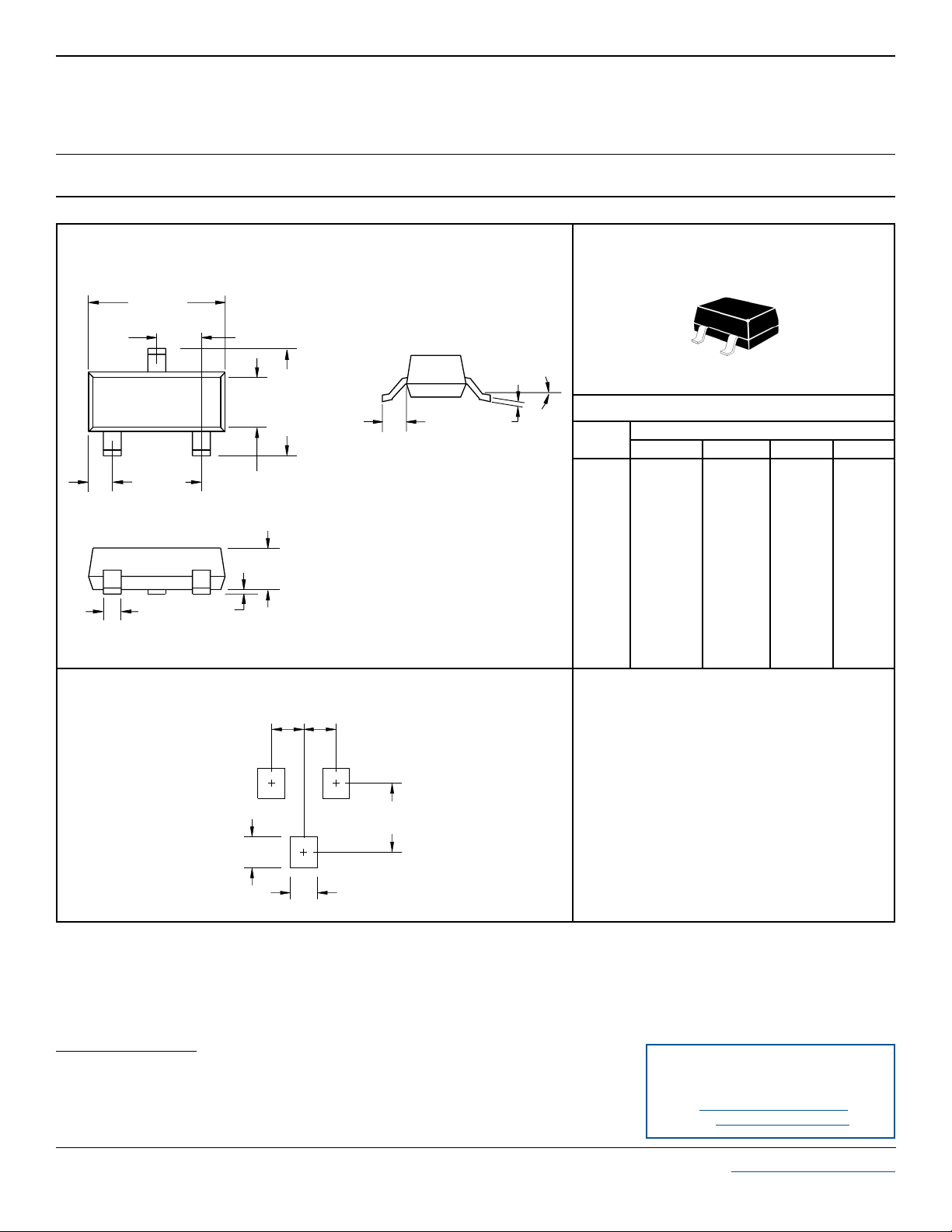
PACKAGE OUTLINE & DIMENSIONS
ESOT24LCC-2
PACKAGE OUTLINE
A
L
3
B
1
2
S
K
0º - 10º
PACKAGE DIMENSIONS
J
SOT-23
MILLIMETERS
INCHES
DIM MIN MAX MIN MAX
V
G
A
B
C
D
G
C
H
J
D
H
K
L
S
V
MOUNTING PAD
0.037” (0.95mm)
NOTES
1. Dimensioning and tolerances per ANSI Y14.5M, 1985.
2. Controlling Dimension: Inches
3. Pin 3 is the cathode (Unidirectional Only).
4. Dimensions are exclusive of mold flash and metal burrs.
2.80
1.20
0.89
0.37
1.78
0.013
0.085
0.45
0.89
2.10
0.45
3.04
1.40
1.11
0.50
2.04
0.100
0.177
0.60
1.02
2.50
0.60
0.1102
0.0472
0.0350
0.0150
0.0701
0.0005
0.0034
0.0180
0.0350
0.0830
0.0177
0.1197
0.0551
0.0440
0.0200
0.0807
0.0040
0.0070
0.0236
0.0401
0.0984
0.0236
0.079” (2.00mm)
0.033” (0.85mm)
0.033” (0.85mm)
COPYRIGHT © ProTek Devices 2003
SPECIFICATIONS: ProTek reserves the right to change the electrical and or mechanical
characteristics described herein without notice (except JEDEC).
DESIGN CHANGES: ProTek reser ves the right to discontinue product lines without notice, and that
the final judgement concerning selection and specifications is the buyer’s and that in furnishing
engineering and technical assistance, ProTek assumes no responsibility with respect to the
selection or specifications of such products.
TAPE & REEL ORDERING NOMENCLATURE
1. Surface mount product is taped and reeled in accordance
with EIA-481.
2. Suffix -T7 = 7 Inch Reel - 3,000 pieces per 8mm tape,
i.e.,
ESOT24LCC-2-T7.
3. Suffix -T13 = 13 Inch Reel - 10,000 pieces per 8mm tape,
i.e.,
ESOT24LCC-2-T13
.
Outline & Dimensions: Rev 1 - 11/01, 06012
ProTek Devices
2929 South Fair Lane, Tempe, AZ 85282
Tel: 602-431-8101 Fax: 602-431-2288
E-Mail: sales@protekdevices.com
Web Site: www.protekdevices.com
3 www.protekdevices.com05194.R0 8/03
 Loading...