

Page 1
®
MAIN PRODUCTS CHARACTE RISTICS
ESM765PI-800
RECOVERY RECTIFIER DIODES
I
F(AV)
V
RRM
10 A
800 V
Tj (max) 150°C
V
(max) 1.35 V
F
trr (max) 300 ns
FEATURES
HIGH VOLTAGE CAPABILITY
FAST AND SOFT RECOVERY
THE SPECIFICATIONS AND CURVES
ENABLE THE DETERMINATION OF THE trr
AND I
AT 100°C UNDER USERS
RM
CONDITIONS
MOTOR CONTROLS AND CONVERTERS
SWITCH MO DE POWE R SU PP LIES
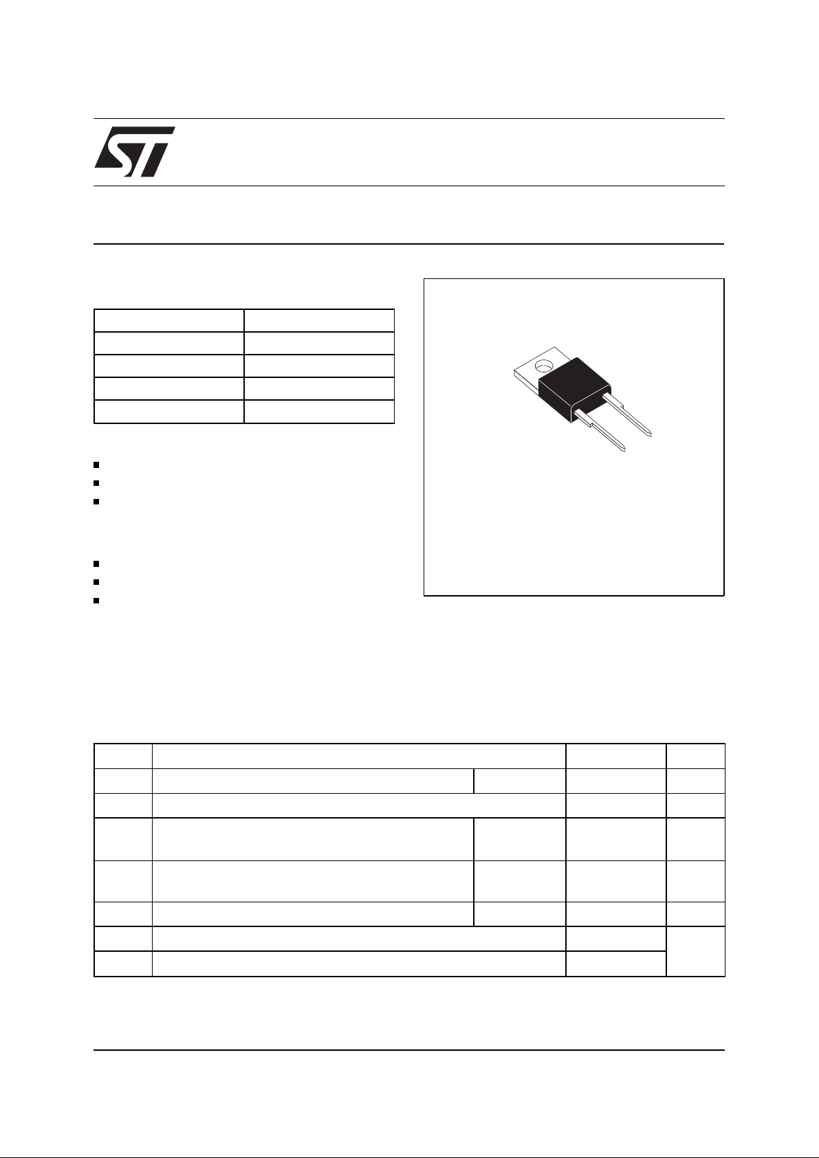
INSULATED PACKAGE: TO-220AC
Insulating voltage = 2500 V
RMS
DESCRIPTION
Fast recovery rectifiers suited for applications in
combination with superswitch transistors.
A
K
Insulated TO-220AC
Symbol Parameter Value Unit
V
RRM
I
F(RMS)
I
F(AV)
I
FSM
Repetitive peak reverse voltage
RMS forward current
Average forward current Tc = 100° C
Surge non repetitive forward current Tp = 10 ms
tp ≤ 20µs800 V
16 A
10 A
δ
= 0.5
120 A
Sinusoidal
P
T
stg
Tj
August 1999 - Ed: 2B
Power dissipation
tot
Storage temperature range
Maximum operating junction temperature
Tc = 100°C 20 W
- 40 to + 150
°
+ 150
C
1/4
Page 2
ESM765PI-800
THERMAL RESISTANCES
Symbol Parameter Value Unit
R
th(j-c)
Junction to case
3.5 °C/ W
STATIC ELECTRICAL CHARACTE RISTICS
Symbol Parameters Test conditions Min. Typ. Max. Unit
*
I
R
**
V
F
Pulse test : * tp = 5 ms, δ < 2 %
Reverse leakage current Tj = 25°CV
Forward voltage drop Tj = 25°CI
** tp = 380 µs, δ < 2 %
Tj = 100°C
Tj = 100°C
= V
R
= 10 A
F
RRM
20 mA
1mA
1.4 V
1.35
To evaluate the conduction losses use the following equation :
P = 1.2 x I
VF = 1.2 + 0.015 I
+ 0.015 x I
F(AV)
F2(RMS)
F
RECOVERY CHARAC TERISTICS
Symbol Test conditions Min. Typ. Max. Unit
trr T
Qrr T
= 25°CI
j
= 25°CI
j
= 1A dIF/dt = - 15A/µs VR = 30V
F
= 10A dIF/dt = - 50A/µs VR = 200V
F
300 ns
2.3
µ
C
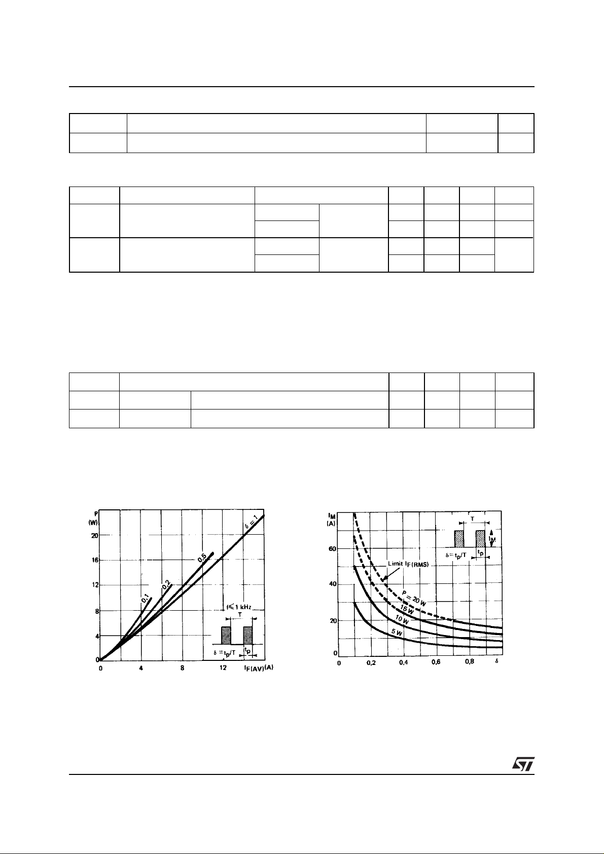
Fig. 1:
Low frequency power losses versus
average current.
2/4
Fig. 2:
Peak current ve r su s f o rm f a ct or.
Page 3

ESM765PI-800
Fig. 3:
Non repetitive peak surge current versus
overload duration.
Fig. 5:
Voltage drop versus forward current.
Fig. 4:
Thermal impedance versus pulse width.
Fig. 6:
Capacitance versus applied reverse
voltage
Fig. 7:
Recovery charge versus dI
F
/dt.
Fig. 8:
Recovery time versus dI
F
/dt.
3/4
Page 4

ESM765PI-800
Fig. 9:
Peak reverse current versus dI
PACKAGE MECHANICAL DATA
Insulated TO-220AC
F
/dt.
B
I
L
b2
C
REF.
Millimeters Inches
DIMENSIONS
Min. Max. Min. Max.
A 14.23 15.87 0.560 0.625
F
a1 4.50 0.177
a2 12.70 14.70 0.500 0.579
A
B 10.20 10.45 0.402 0.411
b1 0.64 0.96 0.025 0.038
a1
b2 1.15 1.39 0.045 0.055
C 4.48 4.82 0.176 0.190
c1 0.35 0.65 0.020 0.026
l2
a2
b1
c2 2.10 2.70 0.083 0.106
e 4.58 5.58 0.180 0.220
F 5.85 6.85 0.230 0.270
I 3.55 4.00 0.140 0.157
c1
e
Information furnished is believed to be accurate and reliable. However, STMicroelectronics assumes no responsibility for the consequences of
use of such information nor for any infringement of patents or other rights of third parties which may result from its use. No license is granted by
implication or otherwi se un der any pat ent or patent rights of STMic roelec tronics. S pecifications ment ioned in t his publ ication are subject to
change without notice. This publication supersedes and replaces all information previously supplied.
STMicroelectronics products ar e not authorized for use as critical components in l i fe s upport devices or systems without expres s written approval of STMicroelectronics.
The ST logo is a registered trademark of STMicroe lectronics
© 1999 STMicroelectronics - Printed in Italy - All rights reser ved.
STMicroelectronics GROUP OF COMPANIES
Australia - Brazil - China - Finland - France - Germany - Hong Kong - India - Italy - Japan - Malaysia
Malta - Morocco - Singapore - Spain - Sweden - Switzerland - United Kingdom - U.S.A.
c2
http://www.st.com
L 2.54 3.00 0.100 0.118
l2 1. 45 1.75 0.057 0. 069
4/4
 Loading...