

Page 1
DATA SHEET
ESL NO.. : ESL-R3040VBCE095
CUS NO. : 90702
REV : A / 0
Producer: Auditor: Approver:
CUSTOMER’SAPPROVAL : _______________ DCC : ____________
DRAWING NO. :ESL-DS-0375 DATE :2013-7-10 Page : 1
Page 2
3.0 mm ROTUNDITY LED LAMP
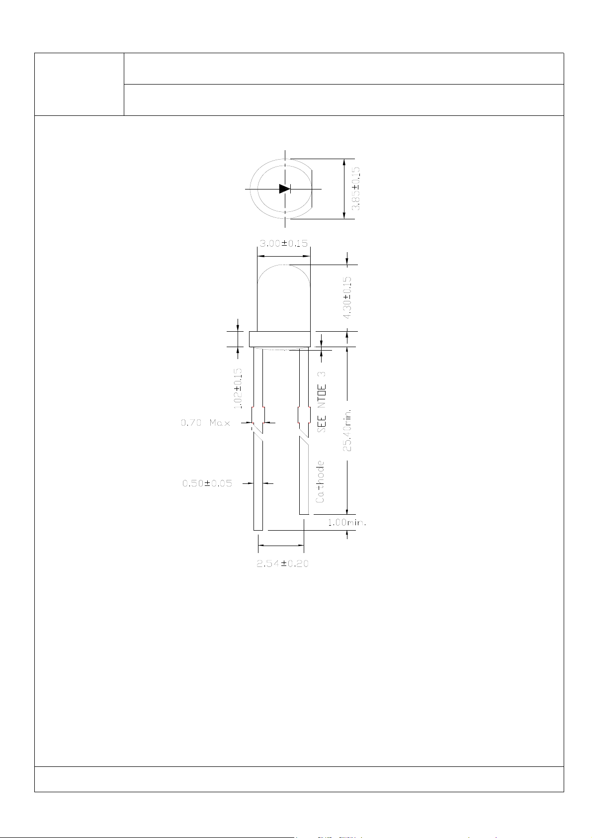
PACKAGE DIMENSIONS
ESL-R3040VBCE095
REV:A/ 0
Note:
1.All Dimensions are in millimeters.
2.Tolerance is ±0.25mm(0.010 ")Unless otherwise specified.
3.Protruded resin under flange is 1.0mm(0.039 ") max.
4.The lamps have sharp and hard points that may injure human eyes or fingers etc., so
please pay enough care in the handling.
5.ESD≤500V.
DRAWING NO. :ESL-DS-0375 DATE :2013-7-10 Page : 2
Page 3
3.0 mm ROTUNDITY LED LAMP
ESL-R3040VBCE095
REV:A/ 0
FEATURES
*
3.0mm DIAROTUNDITY LED LAMP
*
LOW POWER CONSUMPTION.
*
I.C. COMPATIBLE.
*
LONG LIFE SOLID STATE RELIABILITY.
*
PB FREE PRODUCTS(Compliant with EU’s RoHS.)
CHIP MATERIALS
*
Dice Material : GaInN/GaN
*
Light Color : Ultra Blue
*
Lens Color : Water Clear
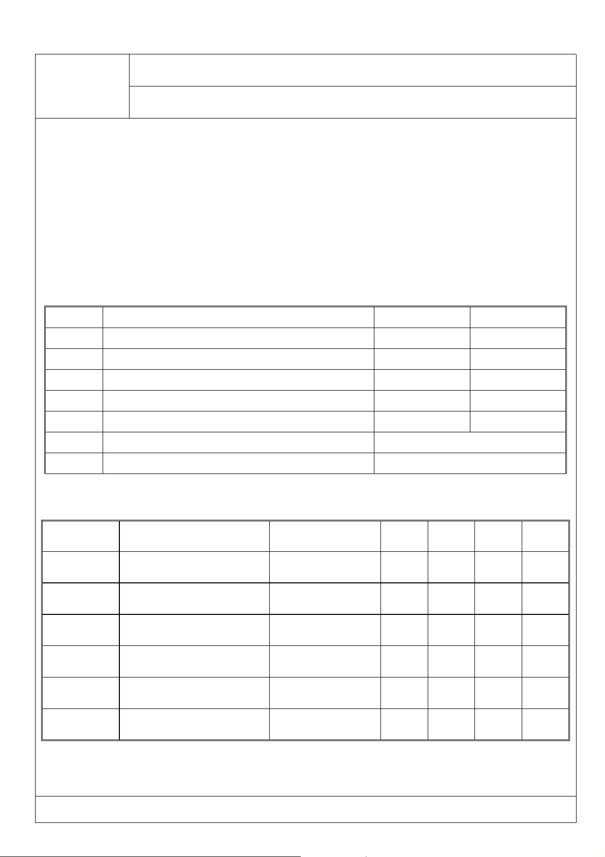
ABSOLUTE MAXIMUM RATING : ( Ta = 25
SYMBOL PARAMETER Ultra Blue UNIT
PAD Power Dissipation 105 mW
VR Reverse Voltage 5 V
IF Average Forward Current 30 mA
°C)
IPF Peak Forward Current Per Chip (Duty=0.1,1KHz) 100 mA
-
Topr Operating Temperature Range -25°Cto85°C
Tstg Storage Temperature Range -40°Cto85°C
Derating Linear From 25°C0.4mA/
ELECTRO-OPTICAL CHARACTERISTICS : ( Ta = 25°C)
SYMBOL DESCRIPTION
Vf Forward Voltage IF=20mA 2.9 3.2 3.6 V
λd Dominant Wavelength IF=20mA 465 -- 475 nm
I
R
Δλ Spectral Line Half-Width IF=20mA 18 nm
2θ Half Intensity Angle IF=20mA 20 deg
Reverse Current VR=5V 10 A
TEST
MIN. TYP. MAX. UNIT
°
C
Iv Luminous Intensity IF= 20mA 4000 4500 5000 mcd
DRAWING NO. :ESL-DS-0375 DATE :2013-7-10 Page : 3
Page 4
3.0 mm ROTUNDITY LED LAMP
ESL-R3040VBCE095
REV:A/ 0
DRAWING NO. :ESL-DS-0375 DATE :2013-7-10 Page : 4
Page 5
3.0 mm ROTUNDITY LED LAMP
ESL-R3040VBCE095
SOLDERING
METHOD SOLDERING CONDITIONS REMARK
IR
REFLOWER
DIP SOLDERING
SOLDERING
IRON
Bath temperature: 240
Immersion time: with 5 sec,1time
Bath temperature: 240℃
Immersion time: with 5 sec ,1time
Soldering iron: 30W or smaller
Temperature at tip of iron: 260℃or lower
Soldering time: within 5 sec.
℃
Solder no closer than 3mm from the
base of the package
Using soldering flux,” RESIN FLUX” is
recommended.
Attached data of temperatuare cure for
your reference
During soldering, takecare not to press
the tip of iron against the lead.
(To prevent heat from being transferred
directly to the lead, hold the lead with a
pair of tweezers while soldering
REV:A/ 0
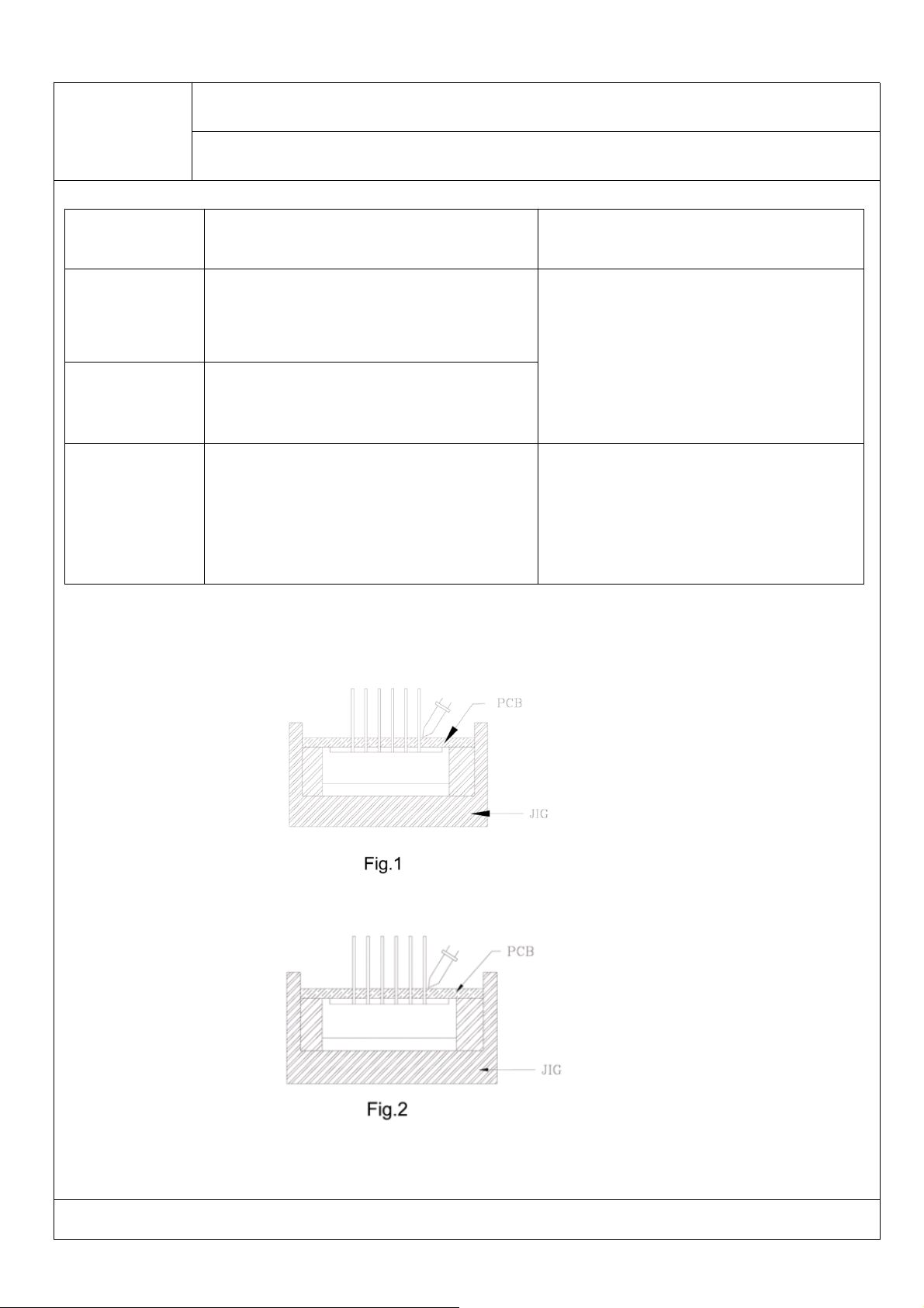
1) When soldering the lead of LED in a condition that the package is fixed with a panel (See Fig.1), be
careful not to stress the leads with iron tip.
2) When soldering wire to the lead, work with a Fig (See Fig.2) to avoid stressing the package.
Regarding solution in the tinning oven for product-tinning, compound sub-solution made of tin & copper and
sliver is proposed with the temperature of Celsius 260. The proportion of the alloyed solution is tin 95.5:
copper 3.5: silver 0.5 by percentage. The time of tinning is constantly 3 seconds.
DRAWING NO. :ESL-DS-0375 DATE :2013-7-10 Page : 5
Page 6
3.0 mm ROTUNDITY LED LAMP
ESL-R3040VBCE095
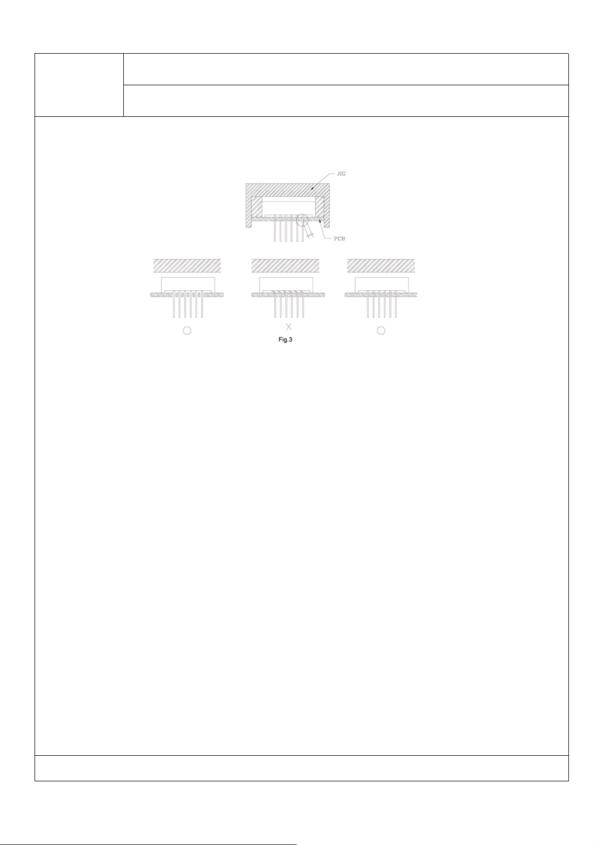
3) Similarly, when a jig is used to solder the LED to PC board, take care as much as possible to avoid
steering the leads (See Fig.3).
4) Repositioning after soldering should be avoided as much as possible. If inevitable, be sure to preserve the
soldering conditions with irons stated above: select a best-suited method that assures the least stress to
REV:A/ 0
the LED.
5) Lead cutting after soldering should be performed only after the LED temperature has returned to normal
temperature.
STORAGE
1) The LEDs should be stored at 30℃or less and 70% RH or less after being shipped from PARAand the
storage life limits are 3 months .
2) PARA LED lead frames are comprised of a stannum plated iron alloy. The silver surface may be affected
by environments which contain corrosive gases and so on. Please avoid conditions which may cause the
LEDs to corrode, tarnish or discolor. This corrosion or discoloration may cause difficulty during soldering
operations. It is recommended that the LEDs be used as soon as possible.
Please avoid rapid transitions in ambient temperature, especially, in high humidity environments where
condensation can occur.
DRAWING NO. :ESL-DS-0375 DATE :2013-7-10 Page : 6
Page 7
3.0 mm ROTUNDITY LED LAMP
ESL-R3040VBCE095
REV:A/ 0
LED MOUNTING METHOD
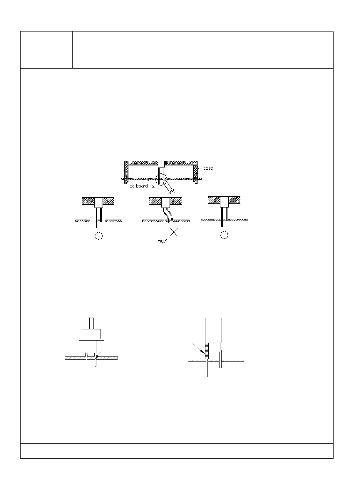
3)When mounting the LED by using a case, as shown Fig.4, ensure that the mounting holds on the PC
board match the pitch of the leads correctly-tolerance of dimensions of the respective components including
the LED should be taken into account especially when designing the case, PC board, etc. to prevent pitch
misalignment between the leads and board holes, the diameter of the board holes should be slightly larger
than the size of the lead. Alternatively, the shape of the holes should be made oval. (See Fig.4)
4)Use LEDs with stand-off (Fig.5) or the tube or spacer made of resin (Fig.6) to position the LEDs.
Tube
Stand-off
Fig.5
Fig.6
DRAWING NO. :ESL-DS-0375 DATE :2013-7-10 Page : 7
Page 8
3.0 mm ROTUNDITY LED LAMP
ESL-R3040VBCE095
REV:A/ 0
FORMED LEAD
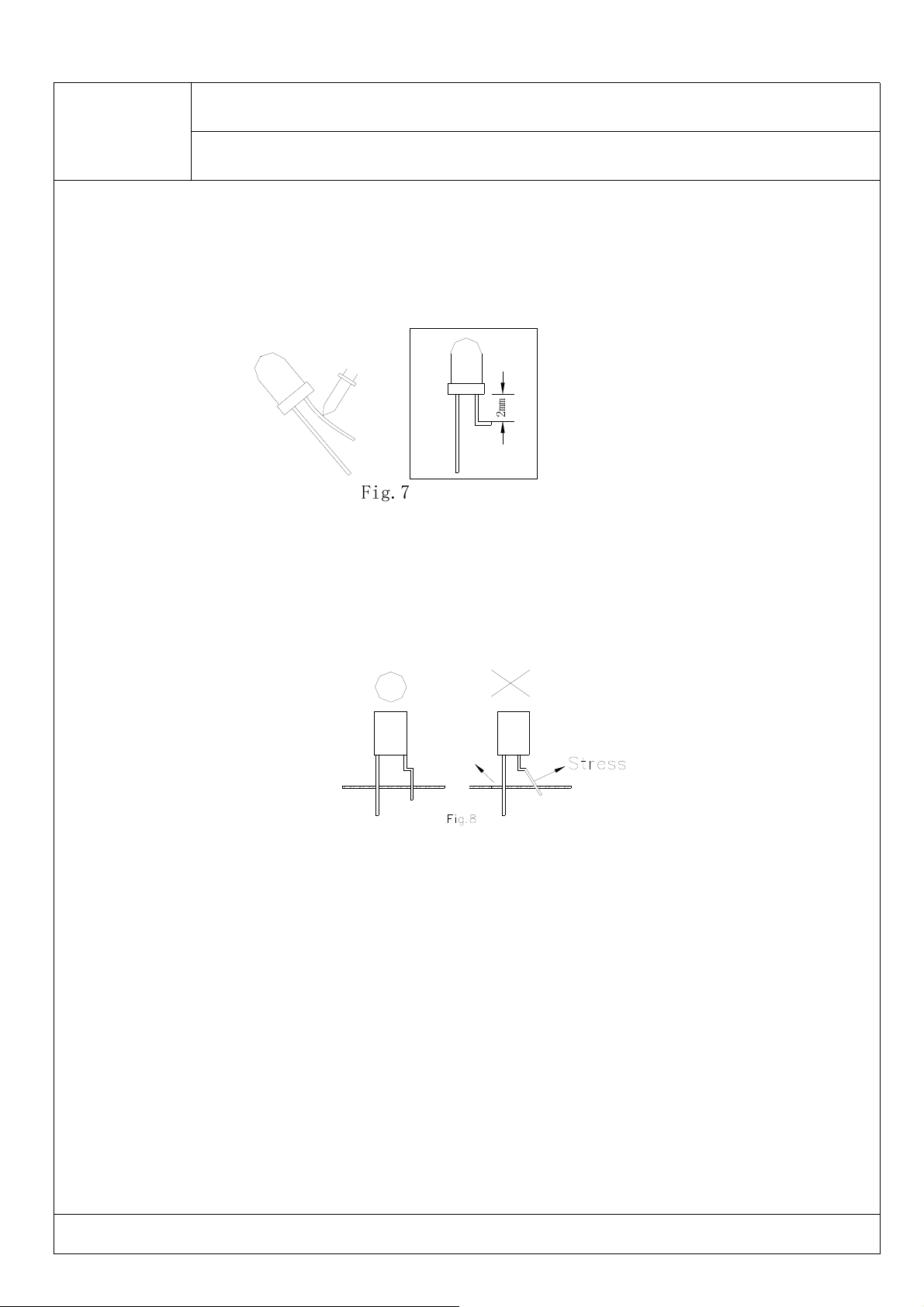
1) The lead should be bent at a point located at least 2mm away from the package. Bending should be
performed with base fixed means of a jig or pliers (Fig.7)
m
m
2
Fig.7
2) Forming lead should be carried our prior to soldering and never during or after soldering.
3) Form the lead to ensure alignment between the leads and the hole on board, so that stress against the
LED is prevented. (Fig.8)
DRAWING NO. :ESL-DS-0375 DATE :2013-7-10 Page : 8
Page 9
3.0 mm ROTUNDITY LED LAMP
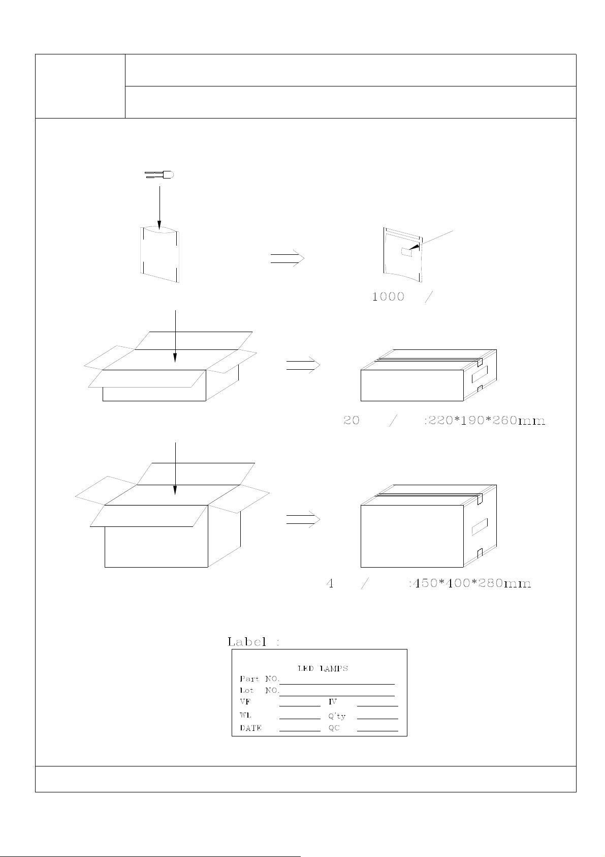
Moisture Resistant Packaging
Static bag
ESL-R3040VBCE095
PCS Bag
REV:A/ 0
Label
Box
Carton
Bag Box
Box Carton
Jiangsu Everstars Electronics Co.,Ltd.
:
:
:
:
:
:
:
:
DRAWING NO. :ESL-DS-0375 DATE :2013-7-10 Page : 9
Page 10
3.0 mm ROTUNDITY LED LAMP
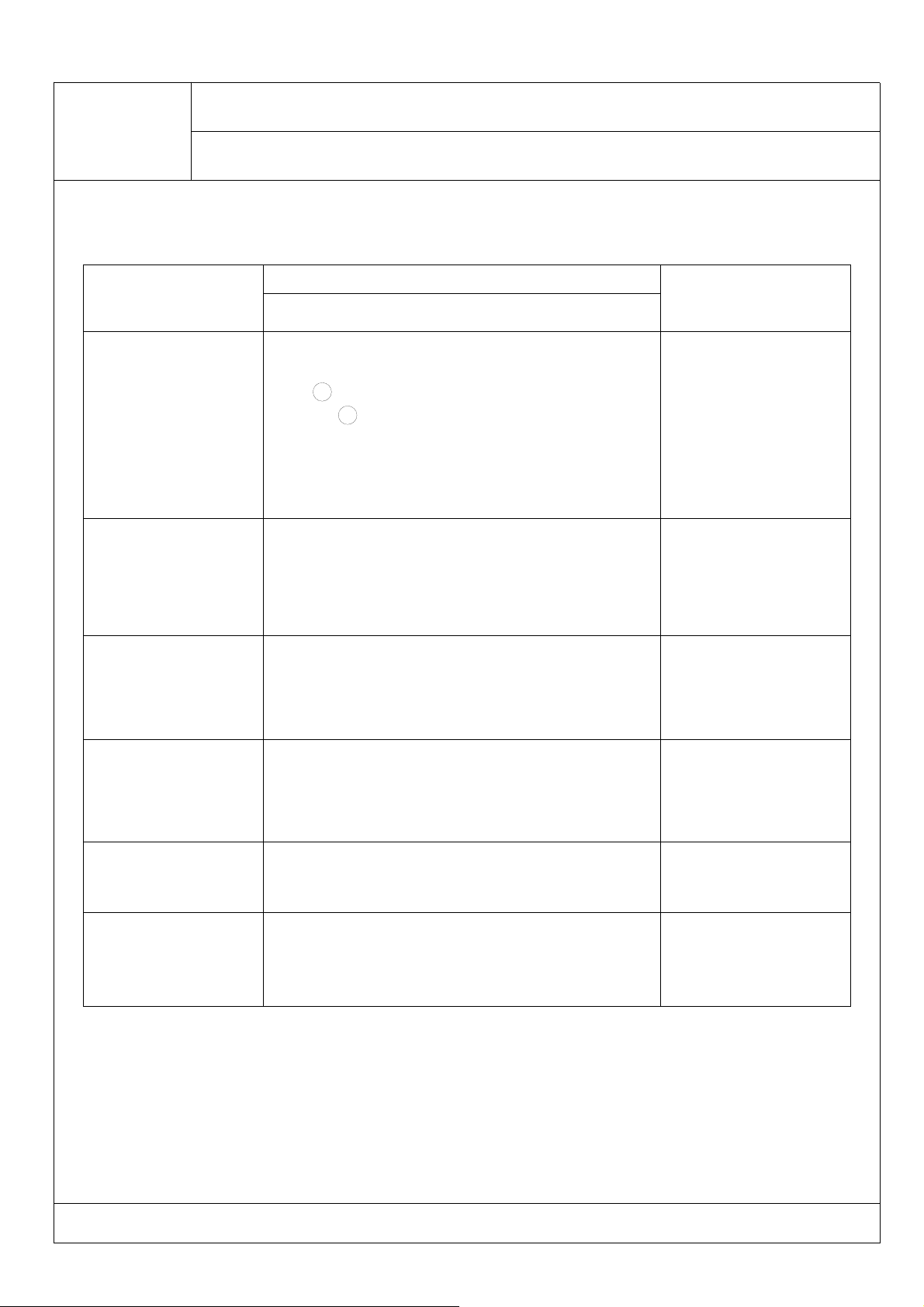
Reliability Test:
Item
OPERATION LIFE
HIGH
TEMPERATURE
HIGH HUMIDITY
STORAGE
ESL-R3040VBCE095
Test Condition
Lamp & IR
Ta:25±5
IF= 20mA RH
1 DYNAMIC:100mA1ms 1/10 duty
2 STATIC STATE: IF
TEST TIME:
168HRS(-24HRS,+24HRS
500HRS(-24HRS,+24HRS
1000HRS(-24HRS,+72HRS
Ta: 65℃±5℃
RH:90~95%RH
TEST TIME:240HRS±2HRS
:<
℃
=60%RH
20mA
=
)
)
)
REV:A/ 0
Reference Standard
MIL-STD-750:1026
MIL-STD-883:1005
JIS C 7021:B-1
MIL-STD-202:103B
JIS C 7021:B-1
105
TEMPERATURE
CYCLING
THERMAL SHOCK
SOLDER
RESISTANCE T,sol:260℃±5
SOLDERABILITY
℃~25℃~
30min 5min 30min 5min
10CYCLES
105℃±5
10min 10min
10CYCLES
DWELL TIME:10±lsec
T,sol:230℃±5
DWELL TIME:5±lsec
℃~
-55
-55℃±5
℃~25℃
℃
℃
℃
MIL-STD-202:107D
MIL-STD-750:1051
MIL-STD-883:1010
JIS C 7021:A-4
MIL-STD-202:107D
MIL-STD-750:1051
MIL-SYD-883:1011
MIL-STD-202:210A
MIL-STD-750-2031
JIS C 7021:A-1
MIL-STD-202:208D
MIL-STD-750:2026
MIL-STD-883:2003
JIS C 7021:A-2
DRAWING NO. :ESL-DS-0375 DATE :2013-7-10 Page : 10
 Loading...