

Page 1

ES51961
3 3/4 MANU DMM
Features
•3 3/4 digits manual and bargraph
display
•Multiple function system
•Logic probe, logic high level
4.0V, 2.4V, 1.5V selectable,
20 MHz
•Analog to digital converter
•Frequency counter (400 MHz)
•OP amplifier
•Full scale range change by ×2,
×10, ×20, ÷ 5, ÷ 10
•Peak hold, catch the P
P
•Data hold, MAX/MIN hold,
Relative data function
(<10 us)
MIN
MAX
and
Description
The ES51961 is a 3 3/4 digits
and bargraph LCD display
measurement system which combines
integrated analog-to-digital converter
(ADC), frequency counter, logic level
tester and OP amplifier, which is
operated with 3V DC power supply.
The ES51961 is suited to voltage,
current, resistance, diode, continuity,
temperature, logic probe and
frequency measurement to 400 MHz.
The frequency counter can
automatically adjust its range to
match the input frequency or manual
setting, over six ranges selectable.
•ZOOM function of bargraph
•Overrange outputs, can be
controlled by RANGE pin
•PH1~PH4 for capacitor
measurement
•RS232
•Low battery detect for 3V/9V
battery
•Crystal or on chip RC oscillator
•Auto-power-off then hold the final
data and re-power-on function
•Reset function
•Back light function
•Voltage reference for resistor
measurement
•Point setting, bargraph disable
•On chip buzzer driver
The logic level probe permits
ES51961 to function as a logic probe
and display logic high voltage level
on the LCD display and turn on a
piezoelectric buzzer.
The other functions are provided
for MAX and MIN holding, data
holding, peak data holding, relative
data, low battery detection, backlight,
zoom, reset, range, auto-power-off ,
re-power-on circuit and RS232 data
output.
•LCD segment check
•3V DC power supply
•100 Pin flat-package
1
2002/11/28
Page 2
ES51961
3 3/4 MANU DMM
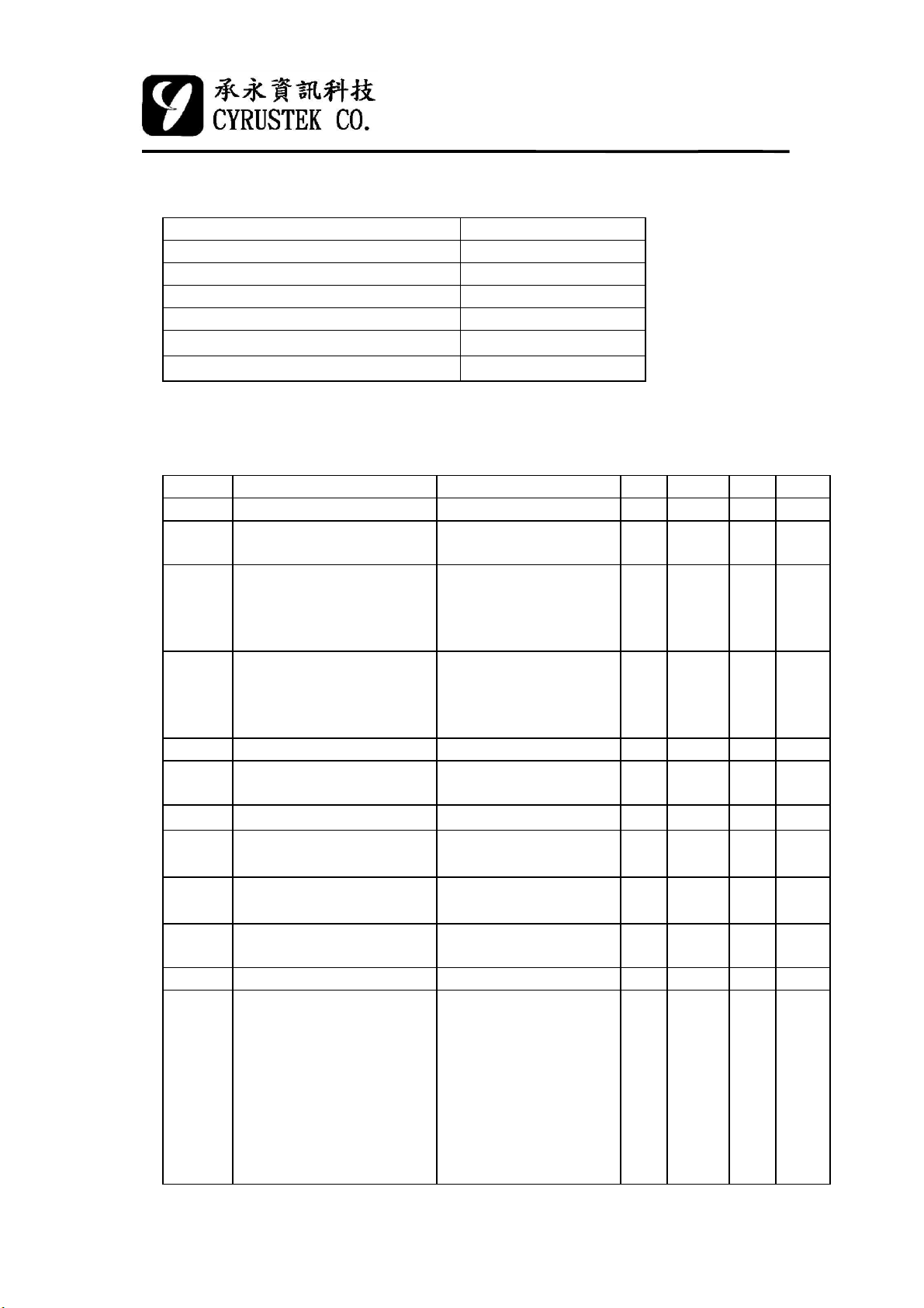
Absolute Maximum Ratings
Characteristics Ratings
Supply Voltage (V- to AGND) -4V
Analog Input Voltage V+ to VDigital Input V- to DGND
Power Dissipation,Flat Package 500mW
Operating Temperature
Storage Temperature
Electrical Characteristics
TA=25℃, V- = -3V
Symbol Parameter Test Condition Min. Typ. Max. unit
V- Power Supply -3.5 -3.0 -2.2 V
Idd
Iss
REV
REB
NLV
NLB
V12 Reference Voltage
V05 Reference Voltage
Operating Supply Current Normal Power On
Rollover Error
(Voltage x 1 )
Rollover Error
(Bargraph)
Nonlinearity
(Voltage x 1 )
Nonlinearity
(Bargraph)
Input Leakage - 1 10 pA
Internal Low Battery Flag
Voltage (for 3V battery)
Zero Input Reading
LCD Drive Voltage,
ANNUNC
Counter Time Base Period fosc=4MHz - 1 - Sec
Internal Pull High to 0V
Current
0℃ to 70℃
-40℃ to 125℃
-
1.352.010mA
Auto-power-off
1M input Resistor
Best Case
Straight Line
V- to AGND -2.5 -2.3 -2.1 V
1MΩ Input Resistor
100KΩ Between
V12 and AGND
100KΩ Between
V05 and AGND
-3.5≦V-≦-2.2
BKLIT,RANGE,SET,
DP1,DP2,BDIS,
BUZIN,XTAL,RESET,
FC1,FC2,FC3,M2,
M10,D10,ZOOM,
PEAK,REL,MAX/MIN
HOLD
(which is connected to
V-)
-
-
-
-
-
-000 000 +000 count
-1.3 -1.2 -1.1 V
-0.57 -0.50 -0.43 V
2.9 3.2 3.5 V
-
-
-
-
-
1.2
± 0.1
± 0.5
± 0.1
± 0.5
uA
﹪F.S.
﹪F.S.
﹪F.S.
﹪F.S.
-uA
2
2002/11/28
Page 3
3 3/4 MANU DMM
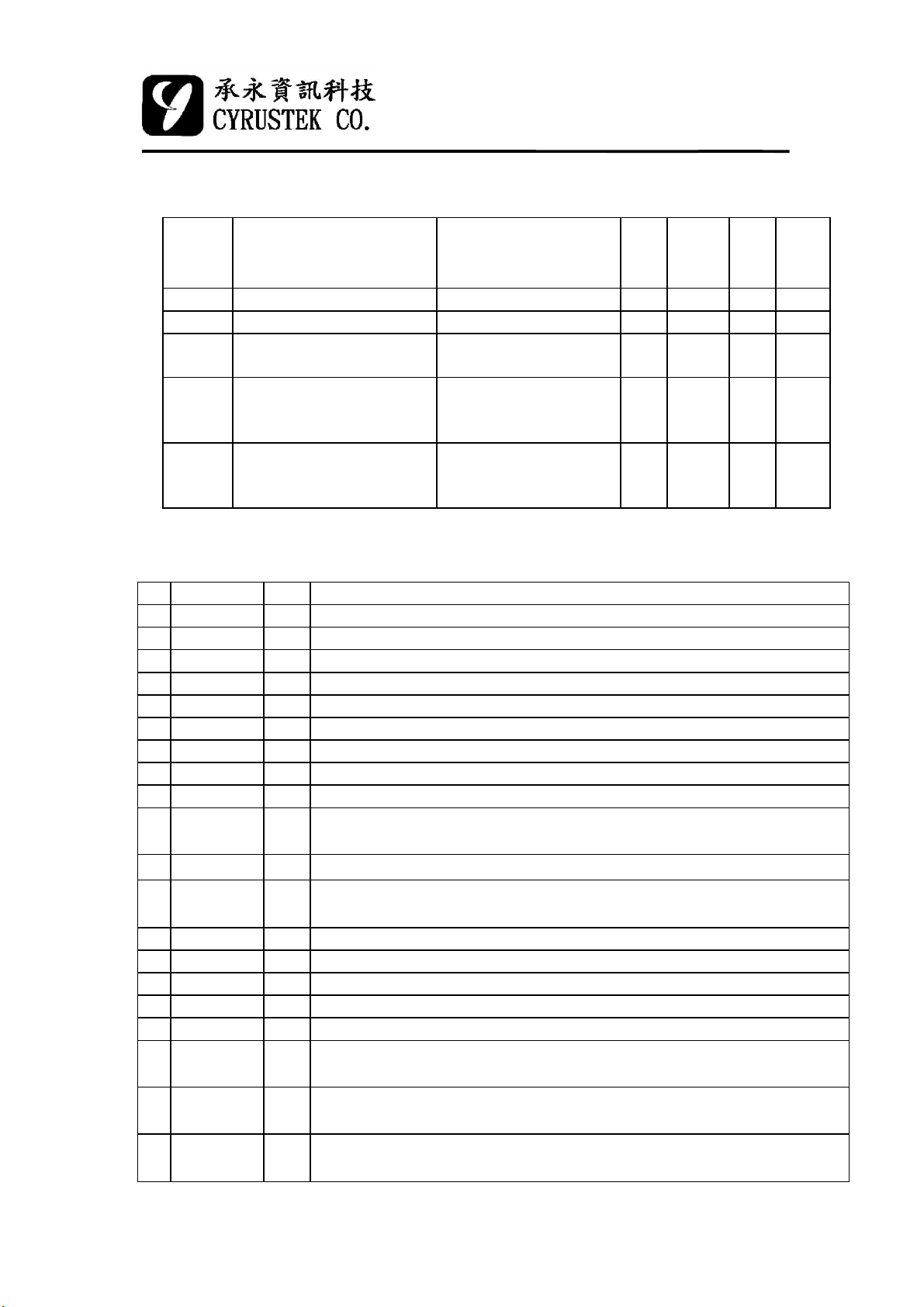
Electrical Characteristics (cont.)
ES51961
TCRF Reference Voltage
Temperature Coefficient
Buzzer frequency Fosc = 4M HZ 2.5 KHZ
LCD drive frequency 78 HZ
VLL Logic low reference
voltage
VLH1
VLH2
VLH3
Logic high reference
voltage
Maximum and minimum
peak value accuracy
(10 uS)
100KΩ Between
V12 and AGND
0℃<TA<70℃
Logic test DC 0.8 V
Logic test DC 4.0
使用 10nF 聚㆚酯薄膜
電容(polyester, Mylar)
- 50 -
2.4
1.5
±2%
±10
ppm/
℃
V
V
V
F.S.
count
Pin Description
Pin Symbol Type Description
1 AGND G Analog ground.
2 AGND G Analog ground.
3 V+ P Positive supply voltage, output of on-chip DC-DC converter.
4 V+ P Positive supply voltage, output of on-chip DC-DC converter.
5 ZH O Output to RC filter for ZOOM mode
6 ZL I Input from RC filter for ZOOM mode
7 CH+ I/O High speed positive connection for reference capacitor.
8 CH- I/O High speed negative connection for reference capacitor.
9 CIH O High speed integrator output. Connected to integration capacitor.
10 BUFHD10 O
11 BUFH O
12 BUFHM10 O
13 CAZH O High speed auto-zero capacitor connection
14 CL+ I/O High resolution positive connection for reference capacitor.
15 CL- I/O High resolution negative connection for reference capacitor.
16 CIL O High resolution integrator output. Connected to integration capacitor.
17 CAZL O High resolution auto-zero capacitor connection.
18 BUFLD10 O
19 BUFL O
20 BUFLM10 O
Integration resistor (1 MΩ) connection for high speed buffer ÷ 10
output.
Integration resistor (100 kΩ) connection for high speed buffer output.
Integration resistor (10 kΩ) connection for high speed buffer ×10
output.
Integration resistor (1 MΩ) connection for high resolution buffer ÷ 10
output.
Integration resistor (100 kΩ) connection for high resolution buffer
output.
Integration resistor (10 kΩ) connection for high resolution buffer ×10
output.
3
2002/11/28
Page 4
ES51961
3 3/4 MANU DMM
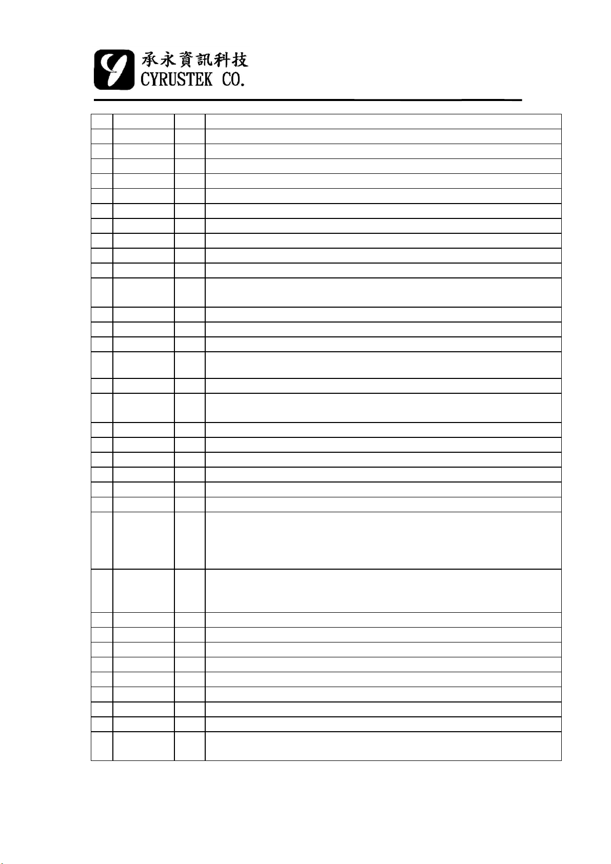
Pin Symbol Type Description
21 V05 O Reference voltage output -0.5V to AGND for resistor measurement.
22 V12 O Reference voltage output -1.2V to AGND.
23 REFLO I Low differential reference input connection
24 REFHI I High differential reference input connection
25 VIN+ I High analog input signal connection.
26 VIN- I Low analog input signal connection.
27 P
MAX
28 P
MIN
29 OP+ I OP + terminal input.
30 OP- I OP – terminal input.
31
OPO O OP output. If this OP is not used, let OPO saturate to V+ can save
32 OR O
33 PKIN I PEAK HOLD ( v.s. AGND ) or Logic Probe ( v.s. V- ) input pin .
34 BKLIT I Back light control pin. Pulse low to make this function active.
35 SLEEP O
36 INT O Integration cycle output (100 ms).
37 RANGE I Semiauto/manual mode and manual range selecting. Pulse low to make
38 SET I Input to set serial data output. Pulse low to make this function active.
39 MP I Ranges setting for MAX/MIN or PEAK mode.
40 DP1 I Decimal point control for voltage measurements.
41 DP2 I Decimal point control for voltage measurements.
42 FREQ I Frequency counter input, biased to 1/2 V- by IC internal circuit.
43 BDIS I When connected to V-, bargraph will be disabled (voltage mode).
44 ANNUNC O Square-wave output at the backplane frequency, synchronized to BP1.
45
SEG23
|
|
67
SEG01
68 BP1 O LCD Backplane 1.
69 BP2 O LCD Backplane 2.
70 BP3 O LCD Backplane 3.
71 BP4 O LCD Backplane 4.
72 PH1 O Phase1 output, for capacitor measurement.
73 PH2 O Phase2 output, for capacitor measurement.
74 PH3 O Phase3 output, for capacitor measurement.
75 PH4 O Phase4 output, for capacitor measurement.
76 BUZOUT O Buzzer output. Audio frequency (2.5 KHz) output which drives a
I/O Maximum peak hold output.
I/O Minimum peak hold output.
power. For example, let OP+=0V and OP-=-3V.
Overrange output. It could be controlled by RANGE pin.
When auto-power-off happen, this pin output will change from V+ to
V-. If re-power-on happen, the output will change from V- to V+.
this function active.
ANNUNC can be used to control display annunciator. Connecting a
LCD segment to ANNUNC will turn it on; connecting a LCD segment
to its backplane will turn it off.
OOLCD Segment line 23.
|
LCD Segment line 01.
piezoelectric buzzer.
4
2002/11/28
Page 5
ES51961
3 3/4 MANU DMM
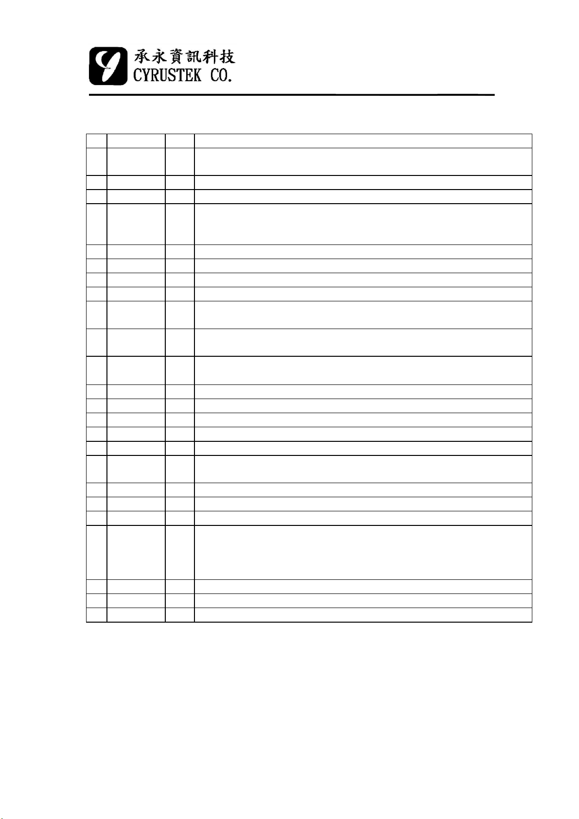
Pin Symbol Type Description
77 BUZIN I Buzzer control input. When connected to V-, turns the buzzer on. (2.5
KHz continuity signal)
78 OSC2 O Crystal oscillator (output) connection.
79 OSC1 I Crystal oscillator (input) connection.
80 XTAL I When unconnected or connected to DGND, the oscillator frequency is
generated by external crystal. When connected to V-, the frequency is
decided by internal RC oscillator.
81 RESET I Pulse low to clear the push function and counter.
82 FC1 I Switch 1 for function selection.
83 FC2 I Switch 2 for function selection.
84 FC3 I Switch 3 for function selection.
85 M2 I When connected to V-, the integration full voltage will be 200mV
instead of 400mV.
86 M10 I When connected to V-,the integration full voltage will be 40mV
instead of 400mV.
87 D10 I When connected to V-, the integration full voltage will be 4V instead
of 400mV, and the absolute value of input voltage must ≤2V.
88 ZOOM I Zoom function select and Logic function setting (buzzer on state).
89 PEAK I Peak hold control pin, pulse low can make this function active.
90 REL I Relative control pin. Pulse low to make this function active.
91 MAX/MIN I Pulse low to make this function active.
92 HOLD I Pulse low to make this function active.
93 BKOUT O If BKLIT pin is pushed, this pin output will change from V- to V+ for
60 sec then returned to V- again, the driving current is about 1 mA.
94 SDO O RS232 output pin.
95 C+ O Positive capacitor connection for on-chip DC-DC converter.
96 C- O Negative capacitor connection for on-chip DC-DC converter.
97 LBAT9 I Low battery voltage setting. If used 3V battery, connected this pin to
AGND, the default low battery voltage will be -2.3V. For 9V battery
power, if this pin input is smaller than V12 (-1.2V), the LCD
annunciator “BATT” will be displayed.
98 V- P Negative supply voltage. Connecting to battery negative terminal.
99 V- P Negative supply voltage. Connecting to battery negative terminal.
100 DGND G Digital ground, connected to battery positive terminal.
*Type: I=Input, O=Output, P=Power, G=Ground
5
2002/11/28
Page 6

Pin Configuration
L
D
G
N
D
B
A
V
V
T
-
-
9
ES51961
3 3/4 MANU DMM
M
A
B
X
K
/
H
S
O
M
O
D
C
C
U
I
L
O
-
+
T
N
D
Z
P
O
R
E
D
O
E
A
1
M
L
K
0
F
M
C
M
1
3
2
0
R
E
F
F
S
C
C
E
2
1
T
AGND
AGND
V+
V+
ZH
ZL
CH+
CH-
BUFHD10
BUFHM10
CIH
BUFH
CAZH
CL+
CL-
CIL
CAZL
CZAL
BUFLD10
BUFL
BUFLM10
V05
V12
REFLO
REFHI
VIN+
VIN-
P
MAX
P
MIN
OP+
OP-
10
5
15
20
25
30
100
35
95
90
40 45
85
50
70
60
80
75
65
55
XTAL
OSC1
OSC2
BUZIN
BUZOUT
PH4
PH3
PH2
PH1
BP4
BP3
BP2
BP1
SEG1
SEG2
SEG3
SEG4
SEG5
SEG6
SEG7
SEG8
SEG9
SEG10
SEG11
SEG12
SEG13
SEG14
SEG15
SEG16
SEG17
P
O
O
K
R
P
I
O
N
I
B
S
R
S
N
K
L
A
E
T
L
E
N
I
E
T
P
T
G
E
D
D
M
P
P
P
2
1
A
F
B
N
R
D
N
E
I
U
Q
S
N
C
S
S
S
E
E
E
G
G
G
2
2
2
1
2
3
6
S
S
S
E
E
E
G
G
G
1
1
2
8
9
0
2002/11/28
Page 7
ES51961
3 3/4 MANU DMM
Operation Mode
Switch Description
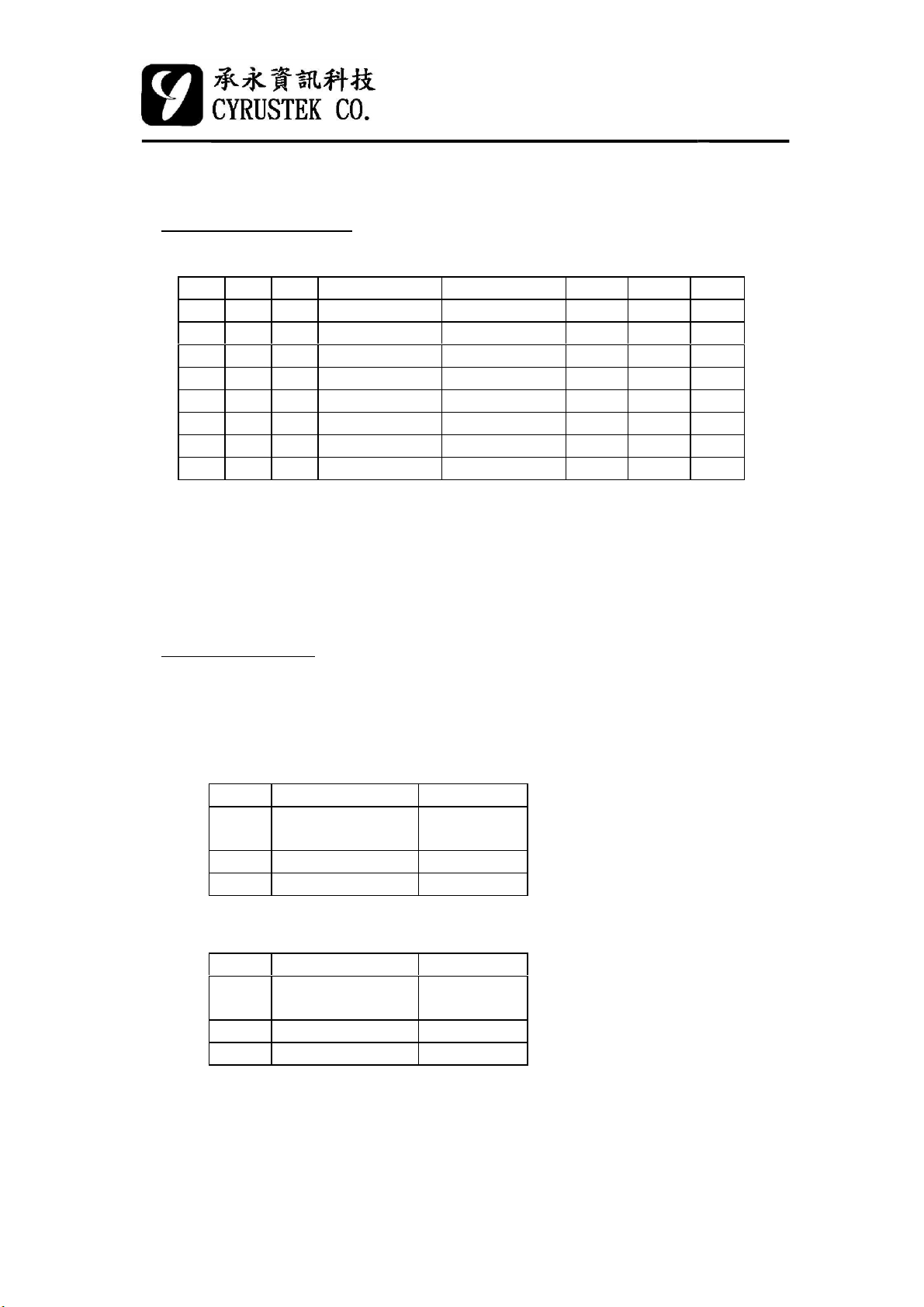
Measurement mode are depend on the logic levels of FC1, FC2, FC3.
FC1 FC2 FC3 Mode Overflow Beep PEAK ZOOM BDIS
1 1 1 Volt1 (*1) O O O O
110Volt2 O X O O
101Volt3 X O O O
100Volt4 X (*2) O O
0 1 1 Continuity X X X X
0 1 0 Frequency (*3) X X X X
0 0 0 Logic (*4) X X (*5) X
001Diode X X X X
*1: The LCD will show "OL" if reading is over 2000 counts if turns D10
function on.
*2: If PEAK connects to V-, the sign annunciator "-" will not display.
*3: The range can be changed by RANGE pin.
*4: The logic high level reference voltage level can be changed by RANGE pin.
*5: This pin is used to change the voltage level of buzzer on.
Analog Section
The ES51961 design incorporates “ZI”, “AZ”, “INT”, “DINT” four phases
which is a dual slope A/D converter. The ADC system including high speed and
high resolution two parts. Its timing setting is as follow:
Voltage:
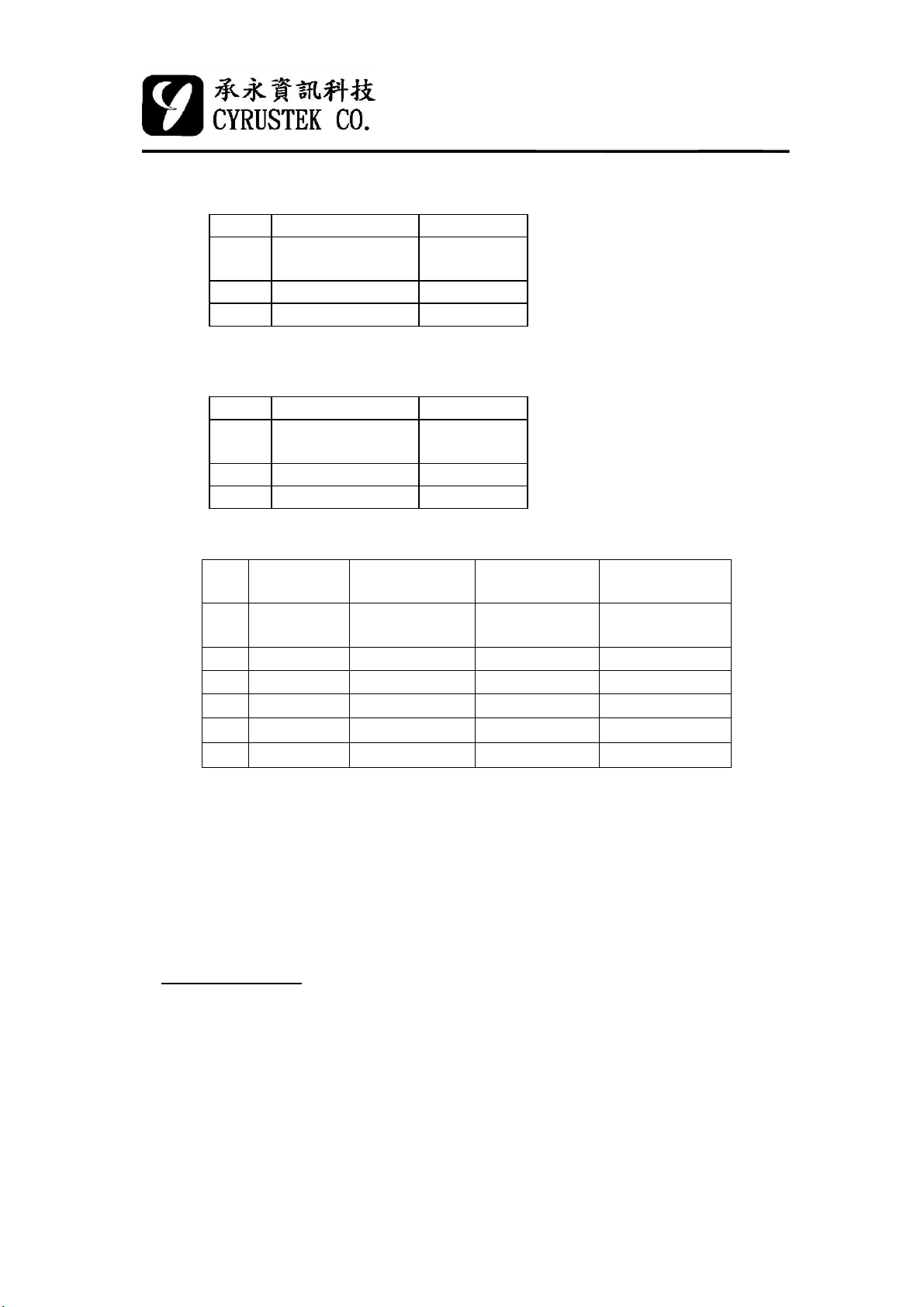
Mode High Resolution High Speed
ZI
AZ
INT 100m sec 10m sec
DINT 400m sec 40m sec
Voltage+M2:
Mode High Resolution High Speed
ZI
AZ
INT 100m sec 10m sec
DINT 200m sec 20m sec
100m sec
150m sec
100m sec
150m sec
20m sec
5m sec
20m sec
5m sec
2002/11/287
Page 8
3 3/4 MANU DMM
Voltage+PEAK:
Mode High Resolution High Speed
ZI
AZ
INT 100m sec 10m sec
DINT 500m sec 50m sec
Voltage+PEAK+M2:
Mode High Resolution High Speed
ZI
AZ
INT 100m sec 10m sec
DINT 250m sec 25m sec
The relation between the scale range and Bar meaning
100m sec
150m sec
100m sec
150m sec
20m sec
5m sec
20m sec
5m sec
ES51961
Scale Enabled pin Input full range Normal mode
Bar meaning
Default or
×1
M10 & D10
M10 40mV 1mV 1mV
×10
M2 200mV 5mV 0.5mV
×2
M10 &M2 20mV 0.5mV 0.5mV
×20
D10 2000mV 100mV 10mV
÷ 10
D10 & M2 2000mV 50mV 5mV
÷ 5
* If M2, M10, D10 is changed under MP="H", the original enabled
function (ex: HOLD, MAX/MIN, REL, PEAK) and the input data will be
reset, but the OR output will not be changed. On the contrary, when
MP="L", see the explication of MP and OR at page 15 please.
* When M2, M10, or D10 is changed, we must recalibrate if we will use
PEAK function again.
400mV 10mV 1mV
Zoom mode
Bar meaning
LOGIC Probe
(1)Logic State & High Voltage Level & Buzzer on Level
There are three kind of independent LOGIC high level, 4.0V, 2.4V and
1.5V (changed by RANGE pin), and buzzer on "H", "-" and "L" level
(changed by ZOOM pin) can be selected individually. The Logic low level is
always 0.8V and the response frequency is 20MHz.
8
2002/11/28
Page 9
ES51961
3 3/4 MANU DMM
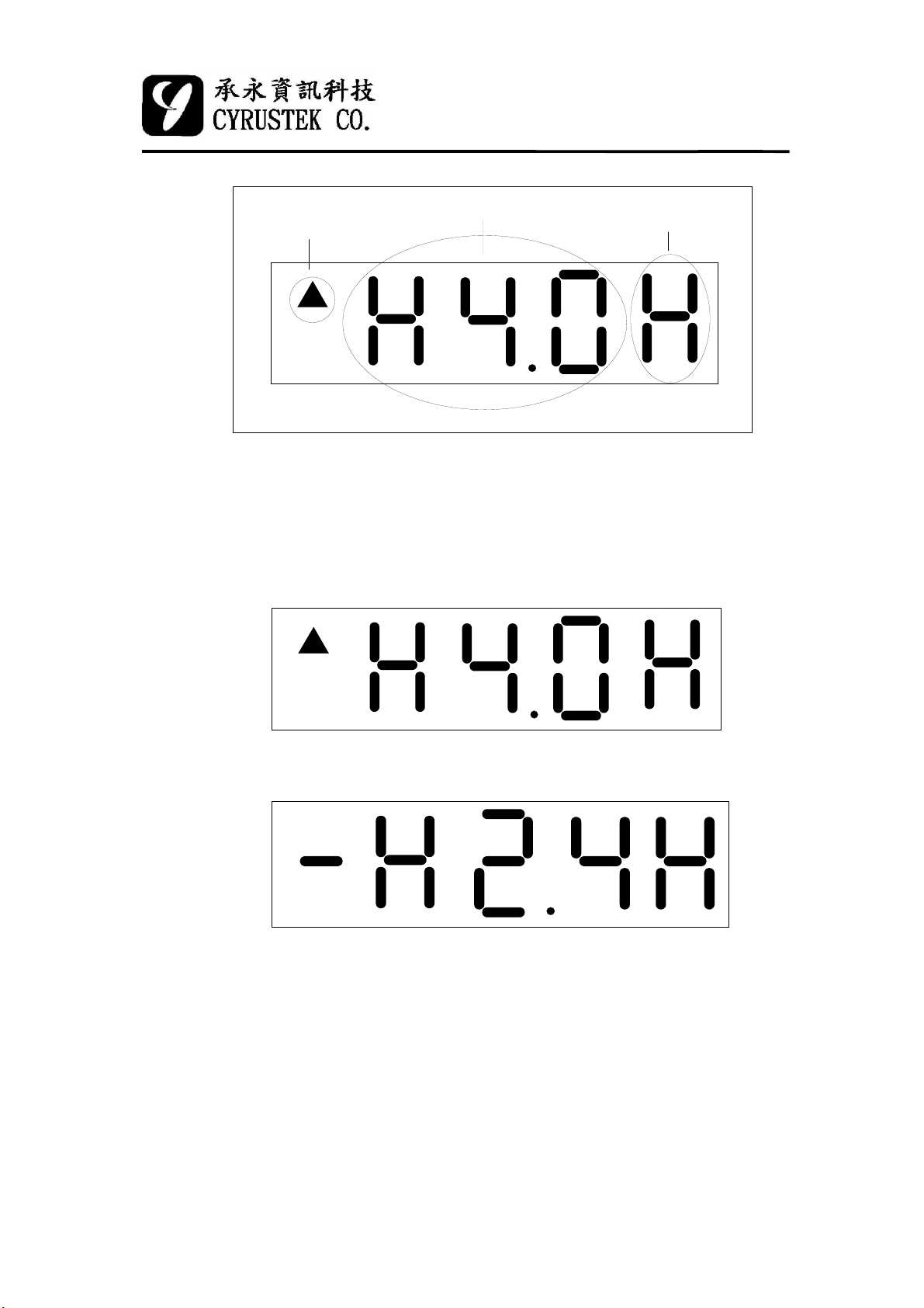
present LOGIC state
LOGIC high level setting
The default LOGIC mode panel
LOGIC probe input high should connect to PKIN pin, the LOGIC probe
input low should connect to V- pin (not VIN- pin), so the maximum voltage
difference between LOGIC high & low can be 6V.
Example:
buzzer on level
The above panel means now is logic high (the input > 4.0V) and the
buzzer turn on.
The above panel means now is logic unknown (the input between
0.8V~2.4V) and once the LOGIC level change to high (>2.4V), the
buzzer will turn on.
9
2002/11/28
Page 10
ES51961
3 3/4 MANU DMM
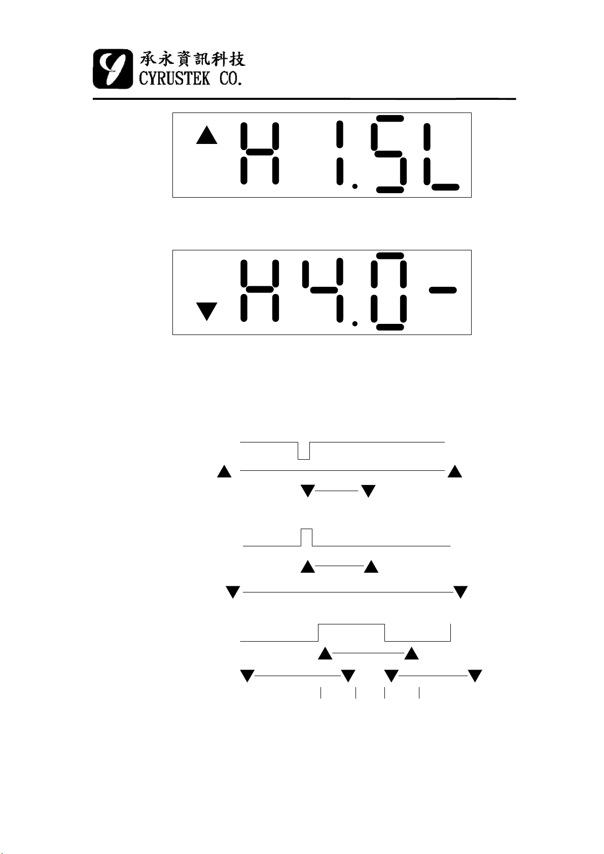
The above panel means now is logic high (the input > 1.5V) and once
the LOGIC level change to low (<0.8V), the buzzer will turn on .
The above panel means now is logic low (the input<0.8V) and once the
LOGIC level change to unknown (0.8V~4.0V), the buzzer will turn
on .
(2) The relation between the input and LCD annunciator
0.1 us
<1> Pulse low input
300 ms
0.1 us
<2> Pulse high input
300 mS
600 ms 600 ms
<3> Period input
Hi
Lo
Hi
Lo
Hi
Lo
300 ms 300 ms
10
2002/11/28
Page 11
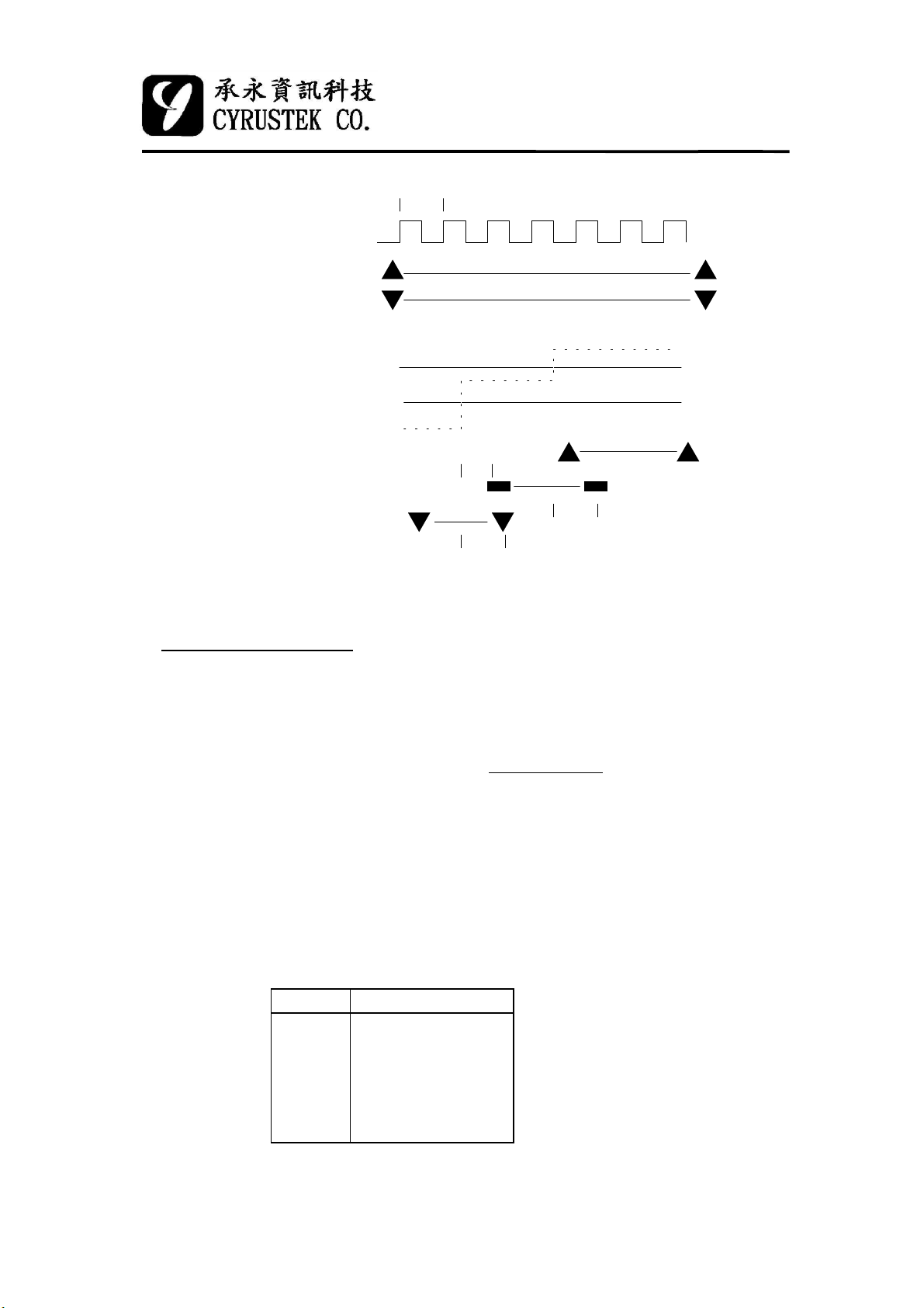
0.1 us
ES51961
3 3/4 MANU DMM
<4> Period input(10M)
<5> Unknow
Frequency Counter
Hi
Lo
VH(4.0,2.4,1.5V)
VL(0.8V)
input
0.5~1 ms
300 ms
300 ms
The timebase of ES51961 is derived by a crystal or internal RC clock
oscillator. The timebase of counter is :
4,000,000
Tcount =
Fosc
Thus, the counter will operate with a 1 second timebase when a 4MHz crystal
oscillator is used. For accurate frequency measurement, a crystal oscillator is
recommended. The frequency counter can automatically select the proper range.
Autorange operation extends over five decades from 1 Hz to 399.9 MHz.
Range Full Scale
FR1
FR2
FR3
FR4
FR5
FR6
3.999 KHZ
39.99 KHZ
399.9 KHZ
3.999 MHZ
39.99 MHZ
399.9 MHZ
11
2002/11/28
Page 12
ES51961
3 3/4 MANU DMM
Continuity
If the input voltage (VIN+~VIN-) make the bargraph number ≤3, a 2.5
KHz signal will come out from BUZOUT pin.
Diode
If the input voltage (VIN+~VIN-) high resolution counts ≥2000, the LCD
will display “OL” and no overflow beep exist. If the bargraph number ≤3, a 2.5
KHz signal will come out from BUZOUT pin.
Push mode
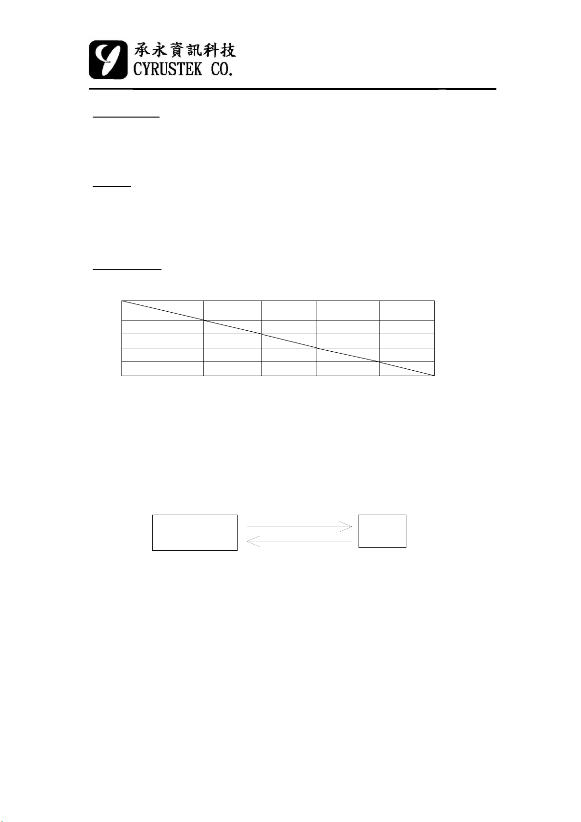
The relation between HOLD, MAX/MIN, REL, PEAK function.
enable mode
active mode
(1)HOLD X X X
(2)PEAK O X X
(3)MAX/MIN O X X
(4)REL O X X
HOLD PEAK MAX/MIN REL
*1: If HOLD function is enabled, then MAX/MIN, REL, PEAK function is
disabled.
*2: If PEAK function is enabled, then REL, MAX/MIN function is disabled,
but HOLD function still can be actived.
*3: If MAX/MIN function is enabled, then REL, PEAK function is disabled,
but HOLD function still can be actived.
*4: If REL function is enabled, then PEAK, MAX/MIN function is disabled,
but HOLD function still can be actived
(1) HOLD and RESET:
RESET
(Semiauto)
*1: If continue to press the HOLD pin (logic low) then power on the
ES51961, and release it in 1.2 sec, the all segments will bright until
pressing the HOLD pin again.
*2: Every time this RESET pin pulse to low (0.8~1.6ms), the pushed
function (HOLD, MAX/MIN, REL, PEAK, ZOOM except BKLIT),
auto-power-off function and counter will be reset.
1 push
Data
Hold
2002/11/2812
Page 13
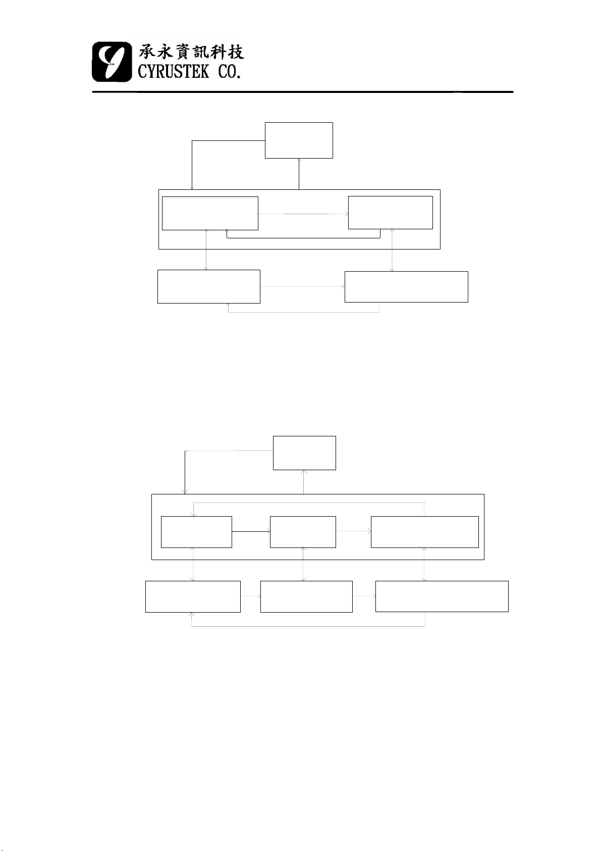
(2) REL+HOLD:
ES51961
3 3/4 MANU DMM
RESET
(Semiauto)
"REL" & "H" active
holded relative value
Note: 1.When REL function is enabled:
Display = Di(N+K)-Di(N), K = 0, 1, 2, 3, ...
Di(N): the reference
Di(N+K): next K step input reading.
2. If the input value Di(N) or Di(N+K) ≧ (± 4000), the
relative value will display “OL”.
(3) MAX/MIN+HOLD:
1 push <1 sec
"REL" active
the relative value
1 push < 1 sec
1 push >1 sec
1 push<1 sec
1 push<1 sec
RESET
(Semiauto)
"REL" blink
the Di(N) value
push HOLDpush HOLD
"REL" blink & "H" active
the Di(N) value
"MAX" active
max. value
push HOLD push HOLD
"MAX" & "H" active
holded max.
1 push > 1 sec
1 push < 1sec
"MIN" active
min. value
"MIN" & "H" active
holded min.
1 push < 1sec
"MAX" & " MIN" blink
current value
push HOLD
"MAX" & "MIN" & "H" blink
current value
2002/11/2813
Page 14
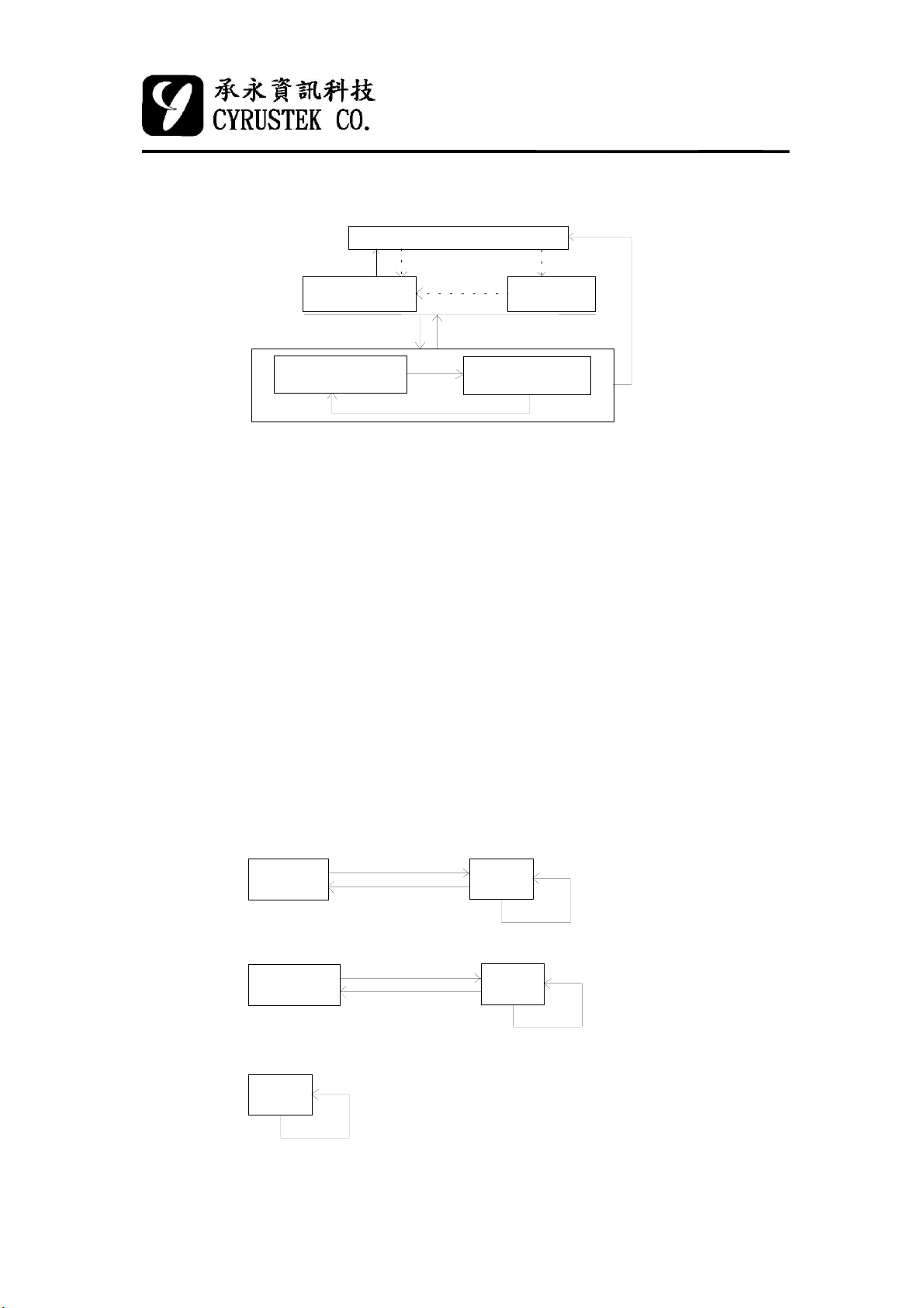
(4) PEAK:
CALIBRATION
1 push > 2 sec
RESE T
(Semiauto)
1 push < 1 sec 1 push > 1 sec
end(*4)
(*1)
ES51961
3 3/4 MANU DMM
end(*5)
(MANU)
1 push > 2 sec
*2: Under the RESET (semiauto) or PEAK mode, if press PEAK
> 2 sec, the PEAK function will enter to calibration mode, the
LCD will show "CAL." and the internal buffer will remember
the internal OP offset voltage then back to the manual mode.
Whenever the PEAK function is enabled again, the reading value
will minus the offset voltage, the purpose is to get the real peak
reading.
*3: Under PEAK mode, the bargraph always show current value.
*4, *5: Please see page 16 note 3.
(5) RANGE:
RANGE pin. The following are the operation flow chart of them.
"PMA X" active
max. peak value
1 push <1 sec
"PMIN" active
min. peak value
(*1): push RANGE > 1 sec
The ranges of voltage, frequency and logic modes is selected by
Voltage mode:
RESET
(Semiauto)
Frequence mode:
RESET
(Automatic)
Logic mode:
default
(4.0V)
1 push < 1 sec
MANU
1 push > 1 sec
1 push < 1 sec
MANU
1 push > 1 sec
1 push can change the logic high
reference voltage between 4.0,
2.4 and 1.5V.
14
1 push < 1 sec
(change OR's state)
1 push < 1 sec
(change measuring range)
2002/11/28
Page 15

ES51961
3 3/4 MANU DMM
MP
The default state is H (0V). When MP="H", if turn MAX/MIN or PEAK on,
OR and range keep original state. If MP=”L”, whether the original state of OR
is “H” or “L”, if active MAX/MIN or PEAK, the OR’s state will be set to “H”.
OR
This pin is used to set/indicate the measured ranges.
The criterion of OR pin changing are:
(1) if under continuity, frequency, logic or diode mode, the OR is always L.
(2) under volt1~volt4 mode and MP="L", if MAX/MIN or PEAK active, the
OR="H".
(3) except situation (1), (2) (i.e. volt1~volt4 mode and MP=”H”), if turning
HOLD, MAX/MIN, REL, PEAK on, the system will enter into manual
mode and OR keep its original state.
(4) except situation (1)~(3), under semiauto mode, if (FC1,FC2,FC3)=(1,1,1)
and D10 on, then
(i) ORÎ"H", if high resolution ≥2000 counts
(ii) OR keeps its original state, if 380≤ high resolution <2000
counts
(iii) ORÎ"L", if high resolution <380 counts
(5) except situation (1)~(4), under semiauto mode the state of OR is:
(i) ORÎ"H", if high resolution ≥4000 counts
(ii) OR keeps its original state, if 380≤ high resolution <4000
counts
(iii) ORÎ"L", if high resolution <380 counts
Note:
1. There are several situations between MP and OR pins. As follow:
(1) MP="H": The state of OR pin can be set by RANGE pin. And if
we push MAX/MIN or PEAK key under semiauto mode, the meter
will enter into manual mode and the OR pin keeps its original state.
(2) MP="L": The state of OR pin can be still set by RANGE pin. But
if we push MAX/MIN or PEAK key under semiauto or manual
mode, the OR pin will change to "H".
15
2002/11/28
Page 16

ES51961
3 3/4 MANU DMM
2. Besides, if we have already turned MAX/MIN or PEAK function on,
the relationship between MP and OR can restate:
(1) MP="H": If the states of M2, M10 or D10 are changed by OR or
rotating mode , then MAX/MIN or PEAK function will be reset.
Though the state of OR pin isn't changed again , it can be changed
by RANGE pin.
(2) MP="L": If the states of M2, M10 or D10 are changed by OR's
state, the MAX/MIN or PEAK function keep in its original state.
3. Under PEAK calibration mode,
(1) MP="H": When calibration is end, the meter will back to manual
mode
(2) MP="L": When calibration is end, the meter will back to its
original mode (manual or semiauto) before the function happen.
4. Whatever MP = "H" or "L", the HOLD, REL, MAX/MIN or PEAK
ZOOM
(1) Voltage mode
function is pushed, the bargraph display will change to ZOOM mode.
(2) Logic mode
unknown Logic (the default is High beep).
BKLIT
When this pin BKLIT is pushed, the BKOUT pin output will change from
complete, the meter will back to the original mode (manual or
semiauto) before these functions happen.
The default status of the bargraph display is from left to right. Once this
This pin is used to turn on the buzzer whether is under High, Low or
V- to V+ for 60 sec then returned to V- again, but if this pin is pushed again
under 60 sec this function will be canceled
16
2002/11/28
Page 17
ES51961
3 3/4 MANU DMM
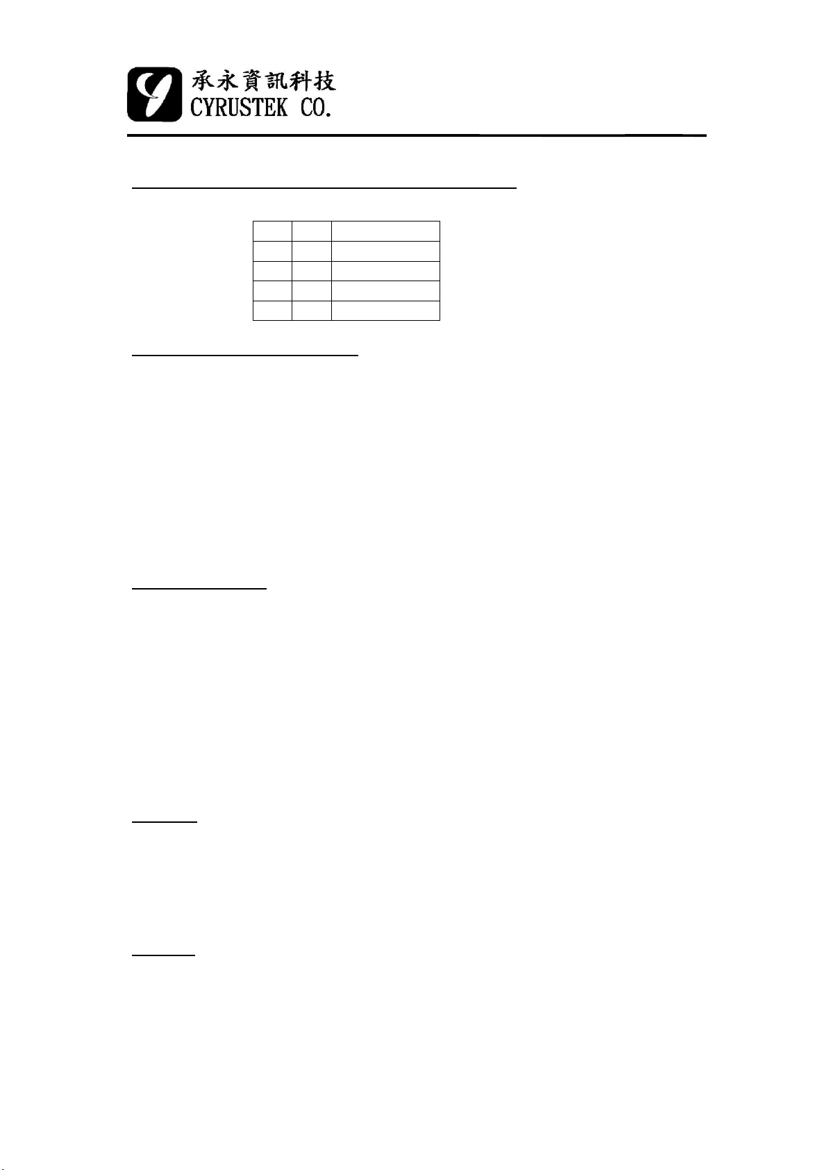
Decimal point select (Under voltage mode)
DP2 DP1 Decimal point
H H None
H L Point1
L H Point2
L L Point3
Auto-Power-Off function
Once power on the ES51961, the auto-power-off function will be enabled
and if the functions are not changed in 30 minutes, the auto-power-off condition
will be happened. When power-off happens, the final data is saved. If continue
to push anyone of the push function (except HOLD pin) then power on the
ES51961, the auto-power-off function will be disabled, and LCD segment
"APO" will be turn off.
Re-Power-On
Once auto-power-off happens, push anyone of the push function or change
the rotary mode can re-power-on the ES51961. When anyone of the push
function is enabled, the storage value will display with HOLD mold (except
logic state), if auto-power-off happened under MAX/MIN (or PEAK, REL)
mode, the P
power-on the ES51961 with rotary mode, the storage value will be clear.
MAX
, P
, or relative and reference value will be keeped. But if re-
MIN
SLEEP
When auto-power-off happens, this pin output will change from V+ to V-,
once re-power on happen, this pin output will change from V- to V+.
Buzzer
(1) The BUZZER turns on in the following condition :
•1 beep: Measurement function changed ,power and re-power on ,HOLD
MAX/MIN, REL, PEAK, BKLIT, SET, RANGE or ZOOM are
17
2002/11/28
Page 18
pushed.
•3.3 beeps: Input reading overrange.
•2.5 KHZ continue: Continuity mode, Diode mode, Logic mode.
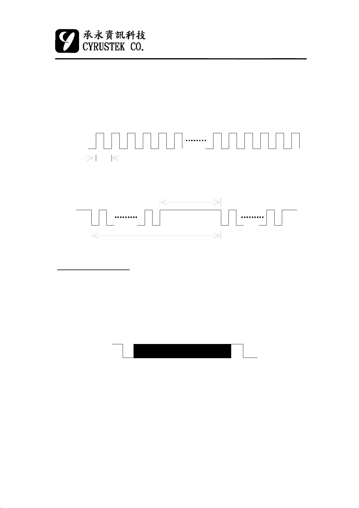
(2) BUZZER output waveform:
2.5 KHz (continued)
ES51961
3 3/4 MANU DMM
beeps (3.33 beeps/sec)
0.4 mS
0.15 sec
0.3 sec
Serial Data Output
The serial data is output two times from SDO pin on each A/D conversion
cycle. The data format satisfy JIS 7BIT transmission code and the baud rate is
2400, it means the receiver terminal can use RS-232 interface to read data.
single package
0V
-3V
0
D0 ~D6
p
1P
LSB MSB
A single package include a start bit (0), D0~D6 (7 bit), a parity check
bit (odd) and a stop bit (1). All the data stream is consist of 110× 2 bits. The
high and low voltage levels correspond to DGND and V- respectively. SDO
remains at 1 (high) when it is inactive. Hence the Start bit (0) could be used as
the triggering signal to begin the reading process.
18
2002/11/28
Page 19
All package
yDig
y
ES51961
3 3/4 MANU DMM
0
0
0
0
range
function2
CR
p
1
0
p
1
0
digit0digit1
p
1
0
status1
p
1
0
LF
p
1
0
digit2digit3
p
1
0
function1
p
1
0
sataus2
p
1
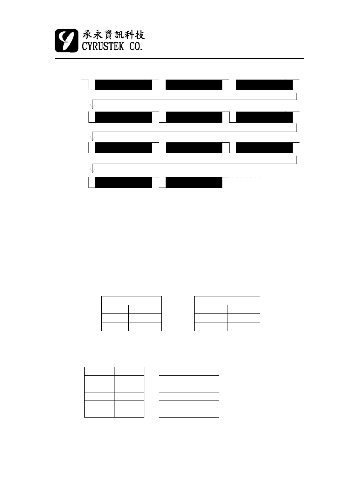
Digit0~3 data is exactly the receiver display number, but the range,
function, status1, status2 data all need written program to judge what the data
mean. Note : LSB bit is sent first, then MSB bit.
The meter always outputs the current input value to the serial port in spite
of HOLD mode. Each block is repeated twice in one conversion cycle. The
detailed data format of each packet is listed below.
p
1
p
1
p
1
(1) RANGE:
Under frequency mode the output is as below:
Range Frequency Range Frequency
0110100 4 KHz 0110000 4 MHz
0110110 40 KHz 0110001 40 MHz
0110010 400 KHz 0110011 400 MHz
Under the other mode (Logic, Voltage), the output is 0110100
(2) DIGIT0~3:
Digit Displa
it Displa
0110000 0 0110101 5
0110001 1 0110110 6
0110010 2 0110111 7
0110011 3 0111000 8
0110100 4 0111001 9
If the input value is overrange (OL), the reading data DIGIT3=4,
DIGIT2=0, DIGIT1=0, DIGIT0=0, but under the frequency mode, DIGIT0~
DIGIT3 output the measured value.
19
2002/11/28
Page 20
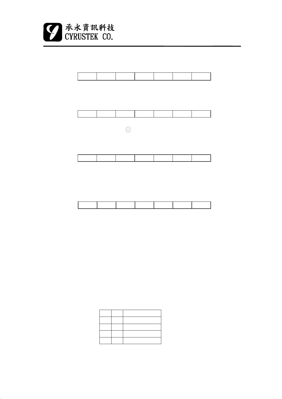
(3) FUNCTION:
FUNCTION1:
ES51961
3 3/4 MANU DMM
BIT7 BIT6 BIT5 BIT4 BIT3 BIT2 BIT1
-: "1" is for the negative (-).
FUNCTION2:
BIT7 BIT6 BIT5 BIT4 BIT3 BIT2 BIT1
MANU: "1" is on " " mode, and "0" is on "AUTO" .
(4) STATUS:
STATUS1:
BIT7 BIT6 BIT5 BIT4 BIT3 BIT2 BIT1
BATT: "1" is for the battery voltage is less than 2.3V±0.2V.
OL: "1" is for the input overrange.
STATUS2:
011
0 1 1 MANU M2 M10 D10
011P
0 1 1 P2 P1 APO OR
-
MAX
FC1 FC2 FC3
P
MIN
BATT OL
BIT7 BIT6 BIT5 BIT4 BIT3 BIT2 BIT1
APO: "1" is for the auto-power-off function enabled
OR: "1" means the voltage of OR pin is V+.
Note: 1. Under Diode mode, if reading is >= 2000 counts, LCD
show "OL".
2. Under Volt1 (ie (FC1, FC2, FC3)=(1, 1, 1) ) & D10
mode, if reading is >= 2000 counts, LCD show "OL".
3. When the offset voltage of PEAK mode is >= 1000
counts, LCD show "OL".
4. except condition 1., 2. and 3., if input reading is ≥4000
counts, LCD show "OL".
P2 P1 Decimal point
0 0 None
0 1 Point1
1 0 Point2
1 1 Point3
(5) CR (BACK): Transmission code "0001101".
(6) LF (LINE FEED): Transmission code “0001010”.
20
2002/11/28
Page 21
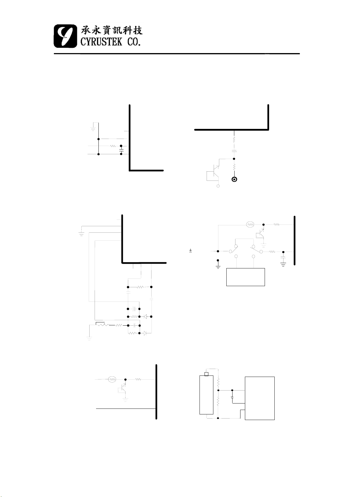
7. Test Circuit
d
N
ES51961
3 3/4 MANU DMM
(1) DC test
+
DC IN
-
(3) AC test
-100 mV
-100 mV
1M
0.1u
REFLO
REFHI
VIN+
VIN-
REFLO
REFHI
VIN+
VIN-
O
P
+
(2) FREQ input test
F
R
E
Q
200
2.2u
C1815
NPN
-3V
PTC
1.5K
FREQ IN
(4) Peak function test
PTC 2.2k
0V
DC
AC
O
O
P
P
O
-
400 mV
INPUT
1M
0.1u
470
PKIN
VIN+
5K
(5) LOGIC test
PTC 2.2k
LOGIC
HIGH
(RED)
LOGIC
LOW
(BLACK)
10K
22K
AC IN
0.1u
22K
88M
1.0u
470
D2
1.0u
D1
0.47u
PKI
V-
AC/DC
rectifier
Under voltage mode, if Peak function
is enabled, PKIN input will be enable
(6) Low battery test(9V)
9V
680K
270K
BATTERY
0V
Note: Light shielding for diode.
ES51961
LBAT9
0.1u
AGND
V-
2002/11/2821
Page 22
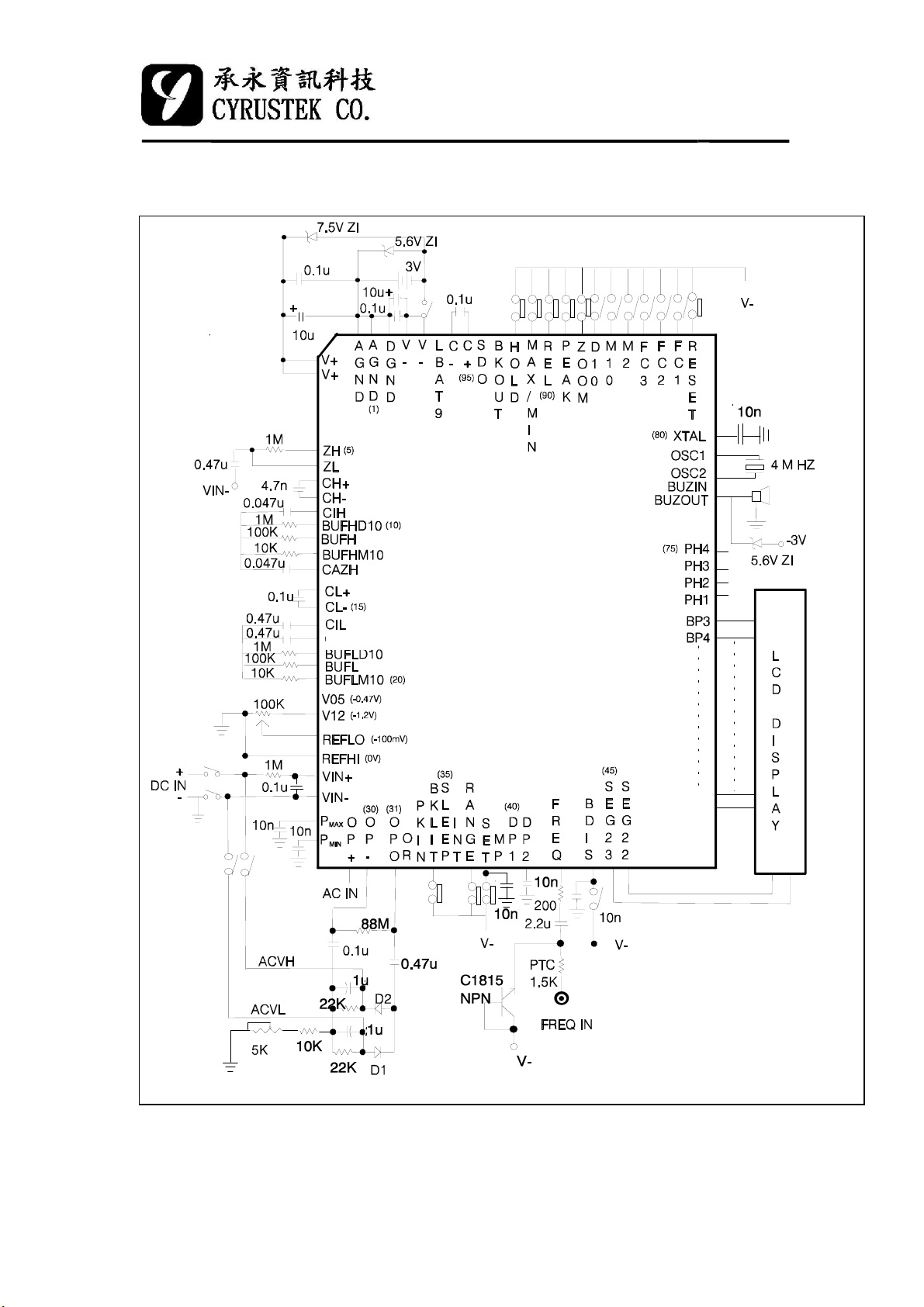
8. Application Circuit
ES51961
3 3/4 MANU DMM
CAZL
2002/11/2822
Page 23
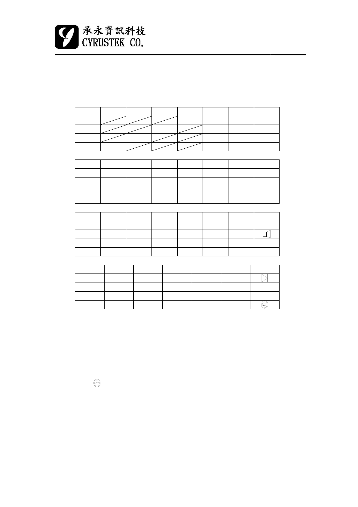
9. The Other
(1) LCD pin assignment
BP1 BP2 BP3 BP4 SEG1 SEG2 SEG3
BP4 APO
BP3 Bar0 BarBP2 Bar1 Bar3 Bar5
BP1 Bar2 Bar4 Bar6
SEG4 SEG5 SEG6 SEG7 SEG8 SEG9 SEG10
BP4 REL 4F 4A 4B MAX 3F 3A
BP3 BATT 4E 4G 4C DP3 3E 3G
BP2 Bar7 Bar9 4D Bar12 Bar14 Bar16 3D
BP1 Bar8 Bar10 Bar11 Bar13 Bar15 Bar17 Bar18
ES51961
3 3/4 MANU DMM
-
SEG11 SEG12 SEG13 SEG14 SEG15 SEG16 SEG17
BP4 3B MIN P
BP3 3C ZOOM DP2 2E 2G 2C
BP2 Bar19 Bar21 Bar23 Bar25 2D Bar28 Bar30
BP1 Bar20 Bar22 Bar24 Bar26 Bar27 Bar29 Bar31
SEG18 SEG19 SEG20 SEG21 SEG22 SEG23
BP4 HOLD 1F 1A 1B KHZ
BP3 DP1 1E 1G 1C MHZ Y
BP2 Bar32 Bar34 1D Bar37 Bar39 X
BP1 Bar33 Bar35 Bar36 Bar38 Bar40
NOTE:
X: always on.
Y: if bargraph is under normal mode (except ZOOM mode), the position
is on for (0, 10, 20, 30, 40).
ZOOM: if bargraph is under zoom mode, the positionis on for (-20, -10,
0, 10, 20).
"": Logic high.
"": Logic low.
" ": manual mode.
MAX
2F 2A 2B P
MIN
2002/11/2823
Page 24
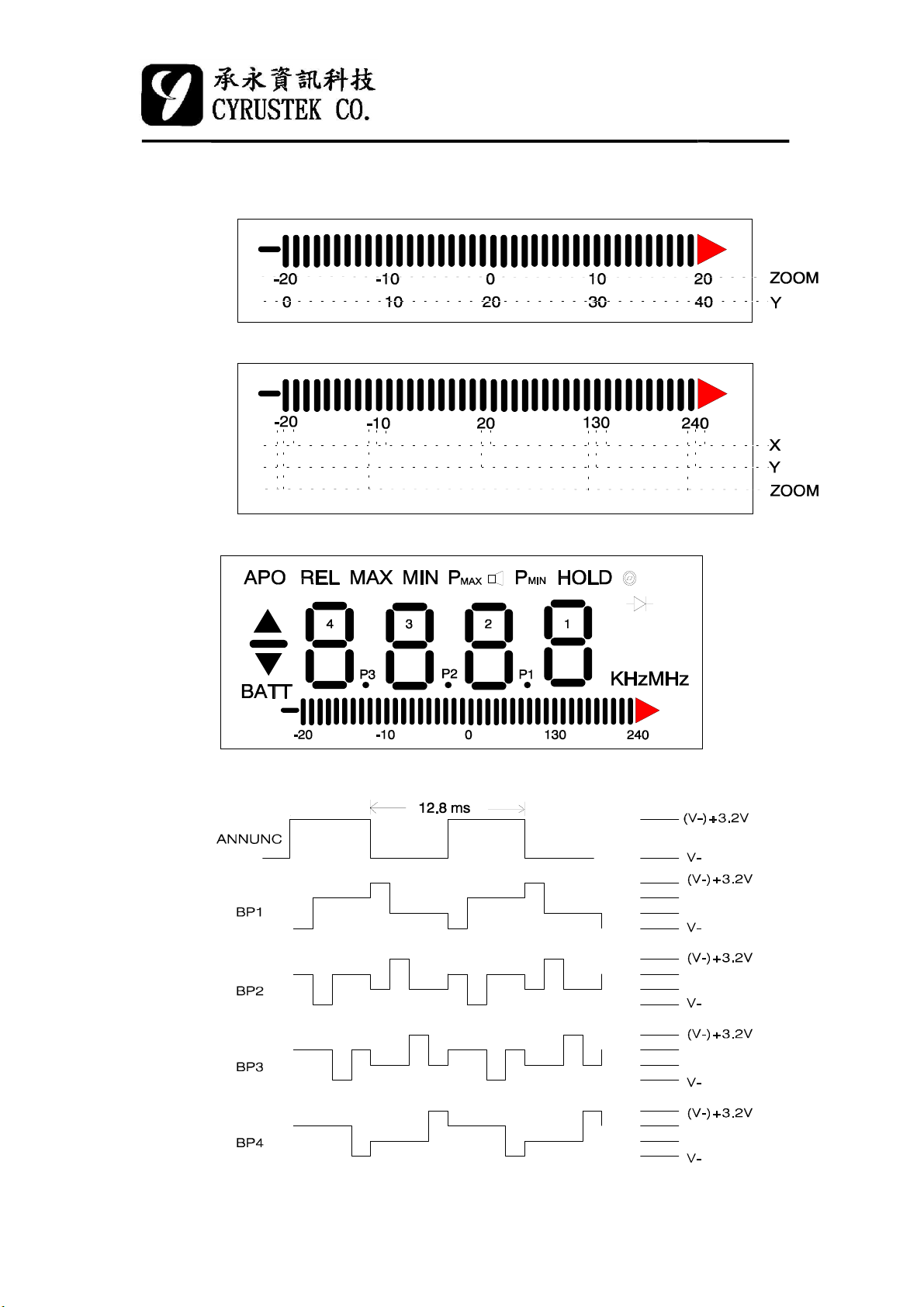
Example for digits under bargraph:
Case1:
Case2:
Example for LCD panel:
ES51961
3 3/4 MANU DMM
(2) Backplane Waveform (Frequency = 78 Hz)
2002/11/2824
Page 25
(3) LCD Display ON Condition
LCD Annunciator Condition
"BATT" Low battery is detected.
"" Logic high function
"" Logic low function
"-" DC voltage and current function and Logic unknown mode.
"P
" Maximum peak function is used.
MAX
"P
" Minimum peak function is used.
MIN
"REL" REL function is used.
"HOLD" HOLD function is used.
"MAX" MAX function is used.
"MIN" MIN function is used.
" "
" "
" "
"KHz" Frequency counter is used.
"MHz" Frequency counter is used.
"APO" Auto-power-off function is used.
Bargraph Bargraph annunciator is only depend on input reading .
" -20, -10, 0, 10, 20" ZOOM function is used.
Continuity-check and Diode-check are used.
Diode-check is used.
Frequency manual mode or completing a calibration on
PEAK mode are used.
ES51961
3 3/4 MANU DMM
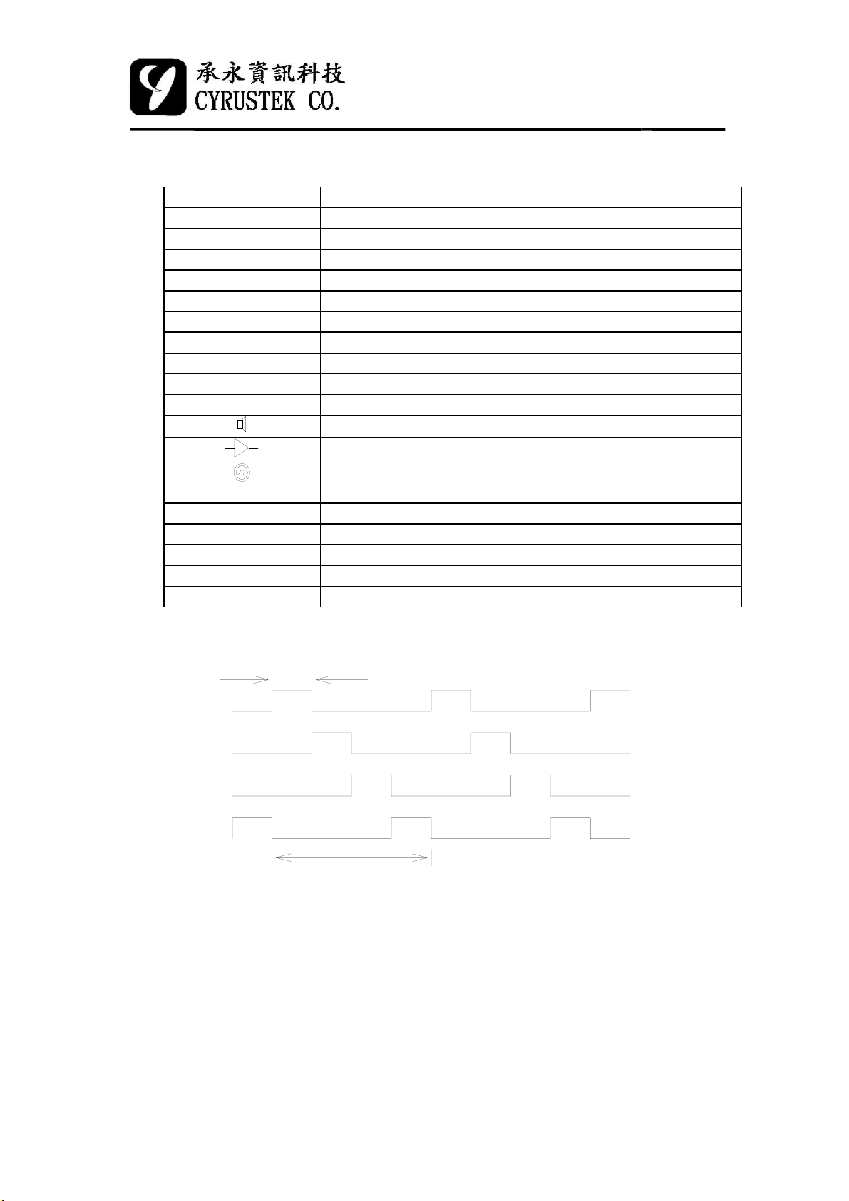
(4) PH1, PH2, PH3, PH4 four phase output
PH1
PH2
PH3
PH4
25.6ms
102.4ms
2002/11/2825
Page 26
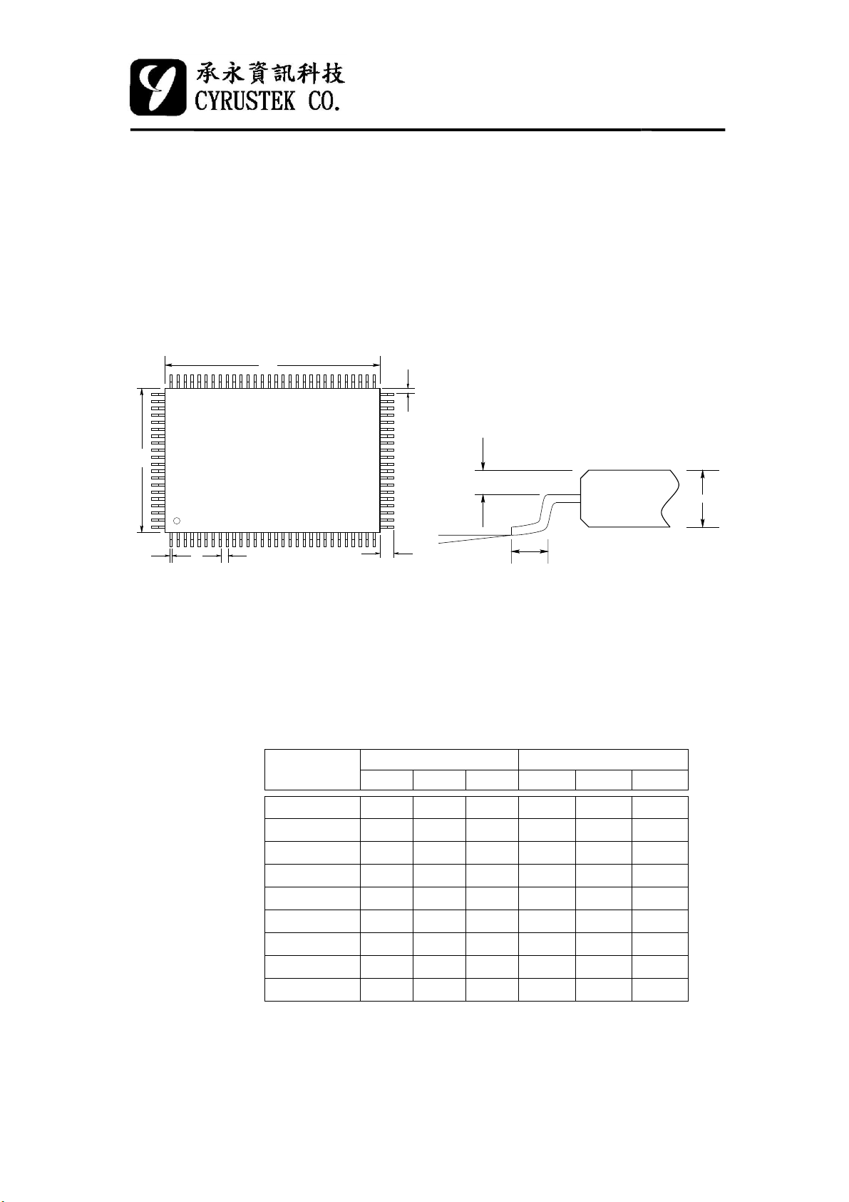
(5)
Package
1 100 Pin QFP Package
W
L
ES51961
3 3/4 MANU DMM
A
b
a
BC
2 Dimension Paramenters
Symbol
W 19.90 20.00 20.10 783.5 787.4 791.3
L 13.90 14.00 14.10 547.2 551.2 551.2
A 0.425 16.7
B 0.20 0.30 0.40 7.9 11.8 11.8
C 0.65 25.6
d 1.05 1.20 1.35 41.3 47.2 47.2
a 2.57 2.72 2.87 101.2 107.1 107.1
D 2.50 98.4
θ
θ
D
Milimeter Mill
Min. Typ. Max. Min. Typ. Max.
o
0
10
d
o
2002/11/2826
 Loading...