

Page 1
Vishay General Semiconductor
Surface Mount Ultrafast Plastic Rectifier
FEATURES
• Glass passivated chip junction
• Ideal for automated placement
• Ultrafast reverse recovery time
• Low switching losses, high efficiency
• High forward surge capability
• Meets MSL level 1, per J-STD-020, LF maximum
peak of 260 °C
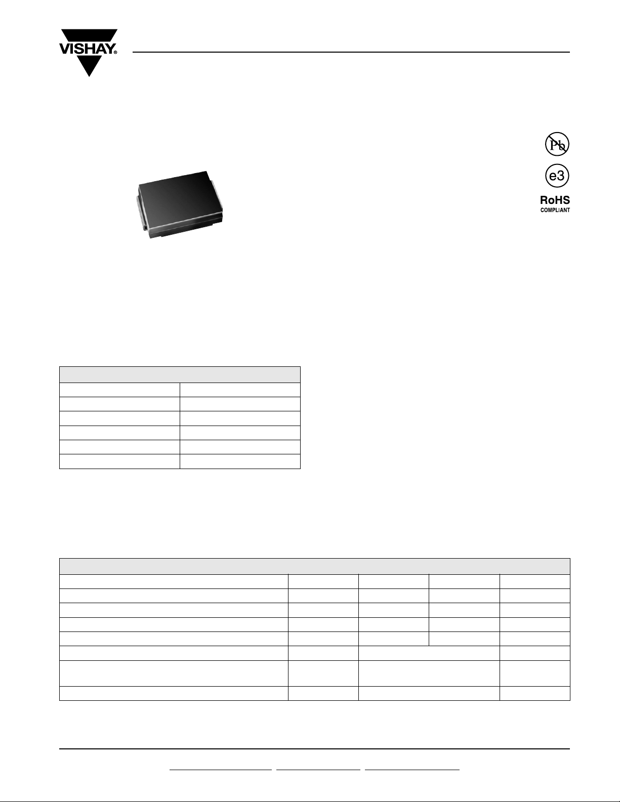
DO-214AB (SMC)
• Solder dip 260 °C, 40 s
• Component in accordance to RoHS 2002/95/EC
and WEEE 2002/96/EC
ES3F & ES3G
TYPICAL APPLICATIONS
For use in high frequency rectification and
freewheeling application in switching mode converters
PRIMARY CHARACTERISTICS
I
F(AV)
V
RRM
I
FSM
t
rr
V
F
T
max. 150 °C
J
300 V, 400 V
3.0 A
100 A
35 ns
1.1 V
and inverters for consumer, computer and
telecommunication.
MECHANICAL DATA
Case: DO-214AB (SMC)
Epoxy meets UL 94V-0 flammability rating
Terminals: Matte tin plated leads, solderable per
J-STD-002 and JESD22-B102
E3 suffix for consumer grade, meets JESD 201 class
1A whisker test, HE3 suffix for high reliability grade
(AEC Q101 qualified), meets JESD 201 class 2
whisker test
Polarity: Color band denotes cathode end
MAXIMUM RATINGS (TA = 25 °C unless otherwise noted)
PARAMETER SYMBOL ES3F ES3G UNIT
Device marking code EF EG
Maximum repetitive peak reverse voltage V
Working peak reverse voltage V
Maximum RMS voltage V
Maximum average forward rectified current at T
Peak forward surge current 8.3 ms single half sine-wave
superimposed on rated load
Operating junction and storage temperature range T
= 110 °C I
L
300 400 V
RRM
RWM
RMS
F(AV)
I
100 A
FSM
- 55 to + 150 °C
J, TSTG
225 300 V
210 280 V
3.0 A
Document Number: 88590
Revision: 20-Nov-07
For technical questions within your region, please contact one of the following:
www.vishay.com
1
Page 2
ES3F & ES3G
Vishay General Semiconductor
ELECTRICAL CHARACTERISTICS (TA = 25 °C unless otherwise noted)
PARAMETER TEST CONDITIONS SYMBOL ES3F ES3G UNIT
Maximum instantaneous forward voltage
Maximum DC reverse current at working
peak reverse voltage
Maximum reverse recovery time
Maximum reverse recovery time
Maximum reverse recovery current
Maximum stored charge
Typical junction capacitance 4.0 V, 1 MHz C
Note:
(1) Pulse test: 300 µs pulse width, 1 % duty cycle
THERMAL CHARACTERISTICS (TA = 25 °C unless otherwise noted)
PARAMETER SYMBOL ES3F ES3G UNIT
Typical thermal resistance
Note:
(1) Units mounted on P.C.B. 5.0 x 5.0 mm (0.013 mm thick) land areas
(1)
(1)
3.0 A VF 1.1 V
T
= 25 °C
A
T
= 100 °C
A
I
= 0.5 A, IR = 1.0 A,
F
I
= 0.25 A
rr
= 1.0 A, dI/dt = 100 A/µs,
I
F
V
= 30 V, I
R
I
= 1.0 A, dI/dt = 100 A/µs,
F
V
= 30 V, I
R
I
= 1.0 A, dI/dt = 100 A/µs,
F
V
= 30 V, Irr = 0.1 IRM
R
= 0.1 IRM
rr
= 0.1 I
rr
RM
I
R
t
35 ns
rr
t
50 ns
rr
IRM 3.0 A
Q
50 nC
rr
J
R
θJA
R
θJL
10
350
30 pF
50
15
µA
°C/W
ORDERING INFORMATION (Example)
PREFERRED P/N UNIT WEIGHT (g) PREFERRED PACKAGE CODE BASE QUANTITY DELIVERY MODE
ES3G-E3/57T 0.211 57T 850 7" diameter plastic tape and reel
ES3G-E3/9AT 0.211 9AT 3500 13" diameter plastic tape and reel
ES3GHE3/57T
ES3GHE3/9AT
(1)
(1)
0.211 57T 850 7" diameter plastic tape and reel
0.211 9AT 3500 13" diameter plastic tape and reel
Note:
(1) Automotive grade AEC Q101 qualified
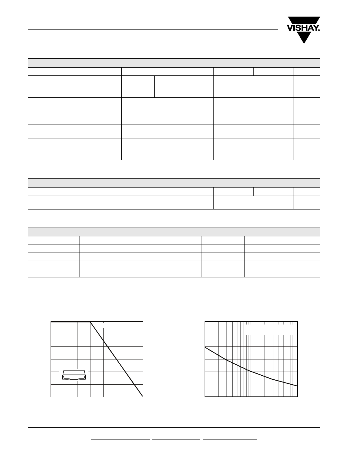
RATINGS AND CHARACTERISTICS CURVES
(T
= 25 °C unless otherwise noted)
A
3.0
ent (A)
2.0
1.0
Average Forward Rectified Curr
0
80 90 100 110 120 130 140 150
Lead Temperature (°C)
Resistive or Inductive Load
Figure 1. Maximum Forward Current Derating Curve
www.vishay.com For technical questions within your region, please contact one of the following:
2
150
125
100
75
50
25
Peak Forward Surge Current (A)
0
1
Number of Cycles at 60 Hz
8.3 ms Single Half Sine-Wave
= 110 °C
at T
L
10
100
Figure 2. Maximum Non-Repetitive Peak Forward Surge Current
Document Number: 88590
Revision: 20-Nov-07
Page 3
ES3F & ES3G
Vishay General Semiconductor
100
TJ = 150 °C
10
TJ = 125 °C
1
TJ = 100 °C
0.1
TJ = 25 °C
Instantaneous Forward Current (A)
0.01
0.1 0.3 0.5 0.7 0.9 1.1 1.3 1.5
Instantaneous Forward Voltage (V)
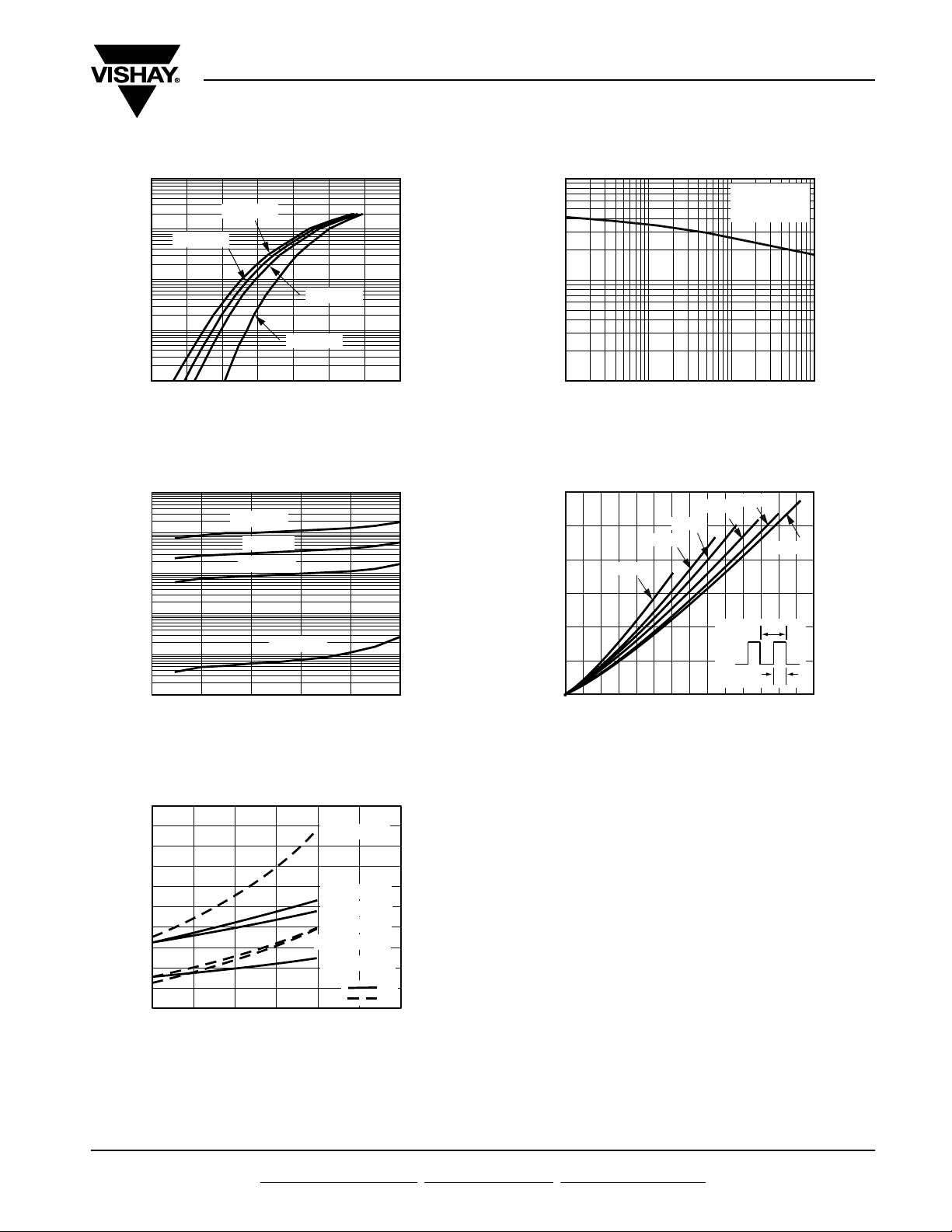
Figure 3. Typical Instantaneous Forward Characteristics
10 000
TJ = 150 °C
TJ = 125 °C
TJ = 100 °C
TJ = 25 °C
Current (µA)
1000
100
10
1
Instantaneous Reverse Leakage
0.1
020406080 100
Percent of Rated Peak Reverse Voltage (%)
Figure 4. Typical Reverse Leakage Characteristics
100
10
TJ = 25 °C
f = 1.0 MHz
= 50 mVp-p
V
sig
Junction Capacitance (pF)
1
0.1 1 10 100
Reverse Voltage (V)
Figure 6. Typical Junction Capacitance
3.0
2.5
2.0
1.5
1.0
Average Power Loss (W)
0.5
0
0 0.5 1.0 1.5 2.0 2.5 3.0 3.5
D = 0.1
D = 0.3
D = 0.2
Average Forward Current (A)
D = 0.5
D = tp/T t
D = 0.8
Figure 7. Forward Power Loss Characteristics
D = 1.0
T
p
200
160
120
80
40
Recovered Stored Charge/
Reverse Recovery Time nC/ns
0
25 50 75 100 125 150 175
Junction Temperature (°C)
Figure 5. Reverse Switching Characteristics
Document Number: 88590
Revision: 20-Nov-07
at 5 A, 50 A/µs
at 2 A, 20 A/µs
at 5 A, 50 A/µs
at 2 A, 20 A/µs
at 1 A, 100 A/µs
at 1 A, 100 A/µs
t
rr
Q
rr
For technical questions within your region, please contact one of the following:
www.vishay.com
3
Page 4

ES3F & ES3G
Vishay General Semiconductor
PACKAGE OUTLINE DIMENSIONS in inches (millimeters)
DO-214AB (SMC)
Cathode Band
Mounting Pad Layout
0.185 (4.69)
MAX.
0.126 (3.20)
0.114 (2.90)
0.103 (2.62)
0.079 (2.06)
0.060 (1.52)
0.030 (0.76)
0.280 (7.11)
0.260 (6.60)
0.320 (8.13)
0.305 (7.75)
0.008 (0.2)
0 (0)
0.246 (6.22)
0.220 (5.59)
0.012 (0.305)
0.006 (0.152)
0.126 (3.20)
MIN.
0.060 (1.52)
0.320 REF.
MIN.
www.vishay.com For technical questions within your region, please contact one of the following:
4
Document Number: 88590
Revision: 20-Nov-07
Page 5

Legal Disclaimer Notice
Vishay
Disclaimer
All product specifications and data are subject to change without notice.
Vishay Intertechnology, Inc., its affiliates, agents, and employees, and all persons acting on its or their behalf
(collectively, “Vishay”), disclaim any and all liability for any errors, inaccuracies or incompleteness contained herein
or in any other disclosure relating to any product.
Vishay disclaims any and all liability arising out of the use or application of any product described herein or of any
information provided herein to the maximum extent permitted by law. The product specifications do not expand or
otherwise modify Vishay’s terms and conditions of purchase, including but not limited to the warranty expressed
therein, which apply to these products.
No license, express or implied, by estoppel or otherwise, to any intellectual property rights is granted by this
document or by any conduct of Vishay.
The products shown herein are not designed for use in medical, life-saving, or life-sustaining applications unless
otherwise expressly indicated. Customers using or selling Vishay products not expressly indicated for use in such
applications do so entirely at their own risk and agree to fully indemnify Vishay for any damages arising or resulting
from such use or sale. Please contact authorized Vishay personnel to obtain written terms and conditions regarding
products designed for such applications.
Product names and markings noted herein may be trademarks of their respective owners.
Document Number: 91000 www.vishay.com
Revision: 18-Jul-08 1
 Loading...