

Page 1

Bridgelux ES Array Series
Product Data Sheet
Introduction
The Bridgelux family of LED Array products delivers high performance, compact and cost-effective solidstate lighting solutions to serve the general lighting market. These products combine the higher efficacy,
lifetime, and reliability benefits of LEDs with the light output levels of many conventional lighting sources.
The Bridgelux ES Array Series has been specified to enable lamp and luminaire designs surpassing
efficacy and quality of light requirements driven by regulatory standards with reasonable system design
margins, enabling lighting product compliance to Energy Star, Title 24, Part L and other global standards.
The Bridgelux ES Array products provide a high performance alternative to conventional solid state
solutions, delivering between 400 and 2000 lumens under application conditions in warm, neutral and
cool white color temperatures. These compact high flux density light sources deliver uniform high quality
illumination without pixilation or the multiple shadow effect caused by LED component based solutions.
To simplify system design for appropriate light output, Bridgelux LED Arrays are specified to deliver
performance under typical use conditions.
These integrated plug and play solutions reduce system complexity and enable miniaturized costeffective lamp and luminaire designs. Lighting system designs incorporating these LED Arrays deliver
comparable performance to that of 20-100 Watt incandescent and halogen, 7-42 Watt compact
fluorescent, and 18-50 Watt HID based luminaires and feature increased system level efficacy and
service life. Typical applications include replacement lamps, task, accent, spot, retail, track, down light,
low bay, wide area, security, wall pack and street lighting.
Features
• Compact high flux density light source
• Uniform high quality illumination
• Streamlined thermal path
• Energy Star / ANSI compliant binning
structure
• More energy efficient than
incandescent, halogen and fluorescent
lamps
• Low voltage DC operation
• Instant light with unlimited dimming
• Long operating life
• RoHS compliant and Pb free
Benefits
Enhanced optical control
•
Clean white light without pixilation
•
Significantly reduced thermal resistance
•
and increased operating temperatures
Uniform consistent white light
•
Lower operating costs
•
Increased safety
•
Easy to use with daylight and motion
•
detectors to enable increased energy
savings
Reduced maintenance costs
•
Environmentally friendly, no disposal
•
issues
101 Portol a A v e n u e , L i v e r m ore, C A 9 4 5 5 1 • T el: (925 ) 5 8 3 - 8 4 0 0 • Fa x: ( 9 2 5 ) 5 8 3 - 8 401 • w w w . b r i d g e l u x.c om
Page 2

Table of Contents Page
Product Nomenclature 3
Average Lumen Maintenance Characteristics 3
Environmental Compliance 3
UL Recognition 4
Minor Product Change Policy 4
Cautionary Statements 4
Case Temperature Measurement Point 5
Flux Characteristics 6
Optical Characteristics 7
Electrical Characteristics 8
Absolute Minimum and Maximum Ratings 9
Typical Performance at Alternative Drive Currents 10
Mechanical Dimensions 13
Typical Radiation Pattern 15
Wavelength Characteristics at Rated Test Current, Tj=25°C 16
Typical Relative Luminous Flux vs. Current, Tj=25° C 18
Typical Light Output Characteristics vs. Temperature 21
Typical Chromaticity Characteristics vs. Temperature 22
Typical Forward Current Characteristics at Tj = 25°C 23
Current Derating Curves 29
Product Binning 35
Luminous Flux Binning Information 35
Color Binning Information 36
Mechanical Assembly and Handling 39
Product Packaging and Labeling 40
Packaging Tube Design 43
Design Resources 44
Bridgelux ES Array Series Product Data Sheet DS11 (06/23/10) Page 2 of 45
Page 3

Product Nomenclature
The part number designation for Bridgelux LED Arrays is explained as follows:
B X R A – A B C D E – R R R R R
Where:
B X R A – designates product family
A – designates color, C for Cool White, N for Neutral White and W for Warm White
B C – designates LED Array product flux, 04 for a 400 lumen array, 08 for a 800 lumen array, 12
for a 1200 lumen array, and 20 for a 2000 lumen array
D E – designates product family
R R R R R – used to designate product options, 00000 by default
The base product part number (BXRA-ABCDE) is indicated on each individual unit, printed on the bottom
of the LED Array.
Average Lumen Maintenance Characteristics
Bridgelux projects that its family of LED Array products will deliver, on average, greater than 70% lumen
maintenance after 50,000 hours of operation at the rated forward test current. This performance
assumes constant current operation with case temperature maintained at or below 70°C. For use beyond
these typical operating conditions please consult your Bridgelux sales representative for further
assistance.
These projections are based on a combination of package test data, semiconductor chip reliability data, a
fundamental understanding of package related degradation mechanisms, and performance observed
from products installed in the field using Bridgelux die technology. Bridgelux conducts lumen
maintenance tests per LM80. Observation of design limits is required in order to achieve this projected
lumen maintenance.
Environmental Compliance
Bridgelux is committed to providing environmentally friendly products to the solid-state lighting market.
Bridgelux LED Arrays are compliant to the European Union directives on the restriction of hazardous
substances in electronic equipment, namely the RoHS directive. Bridgelux will not intentionally add the
following restricted materials to LED Array products: lead, mercury, cadmium, hexavalent chromium,
polybrominated biphenyls (PBB) or polybrominated diphenyl ethers (PBDE).
Bridgelux ES Array Series Product Data Sheet DS11 (06/23/10) Page 3 of 45
Page 4

UL Recognition
Bridgelux product became UL Recognized on 31 March, 2010. Please refer to the UL file E333389.
Bridgelux uses UL Recognized materials with suitable flammability ratings in the LED Array to streamline
the process for customers to secure UL listing of the final luminaire product. Bridgelux recommends that
luminaires are designed with a Class 2 Driver to facilitate the UL listing process.
Minor Product Change Policy
The rigorous qualification testing on products offered by Bridgelux provides performance assurance.
Slight cosmetic changes that do not affect form, fit, or function may occur as Bridgelux continues product
optimization.
Cautionary Statements
CAUTION: CONTACT WITH OPTICAL AREA
Contact with the resin area should be avoided. Applying stress to the resin area can result in damage to
the product.
CAUTION: EYE SAFETY
Eye safety classification for the use of Bridgelux LED Arrays is contained in the CIE S 009/E2002
Photobiological Safety of Lamps and Lamp Systems specification. Bridgelux LED Arrays are classified
under section 6 lamp classification as Risk Group 2 (Moderate Risk). Please use appropriate
precautions. It is important that employees working with LEDs are trained to use them safely. Luminaire
manufacturers should refer to CIE S 009/E2002 to establish the classification of their product.
CAUTION: RISK OF BURN
Do not touch the LED Array or resin area during operation. Allow the LED Array to cool for a sufficient
period of time before handling. The LED Array may reach elevated temperatures such that it can burn
skin when touched.
Bridgelux ES Array Series Product Data Sheet DS11 (06/23/10) Page 4 of 45
Page 5

Case Temperature Measurement Point
A case temperature measurement point location is included on the top surface of the Bridgelux LED
Arrays. The location of this measurement point is indicated in the mechanical dimensions section of this
data sheet.
The purpose of this measurement point is to allow the user access to a measurement point closely linked
to the true case temperature on the back surface of the LED Array. Once the LED Array is installed, it is
challenging to measure the back surface of the array, or true case temperature. Measuring the top
surface of the product can lead to inaccurate results due to the poor thermal conductivity of the top layers
of the array such as the solder mask and other materials.
Bridgelux has provided the case temperature measurement location in a manner which closely ties it to
the true case temperature of the LED Array under steady state operation. Deviations between thermal
measurements taken at the point indicated and the back of the LED Array differ by less than 1°C,
providing a robust method to testing thermal operation once the product is installed.
Bridgelux ES Array Series Product Data Sheet DS11 (06/23/10) Page 5 of 45
Page 6

Flux Characteristics
Table 1: Flux Characteristics
Color
Warm White
Neutral White
Base Part
Number
Typical
Luminous
Flux фv (lm),
T
=60°C
case
[3]
Minimum
Luminous
Flux фv (lm),
Tj=25°C
Flux фv (lm),
[1]
Typical
Luminous
Tj=25°C
Test
Current
(mA)
BXRA-W0401 400 400 440 700
BXRA-W0402 420 400 460 700
BXRA-W0403 400 400 460 250
BXRA-W0802 850 800 930 1050
BXRA-W1202 1200 1200 1320 1200
BXRA-W1203 1240 1200 1370 1050
BXRA-N0402 400 400 440 600
BXRA-N0802 920 880 1020 1050
BXRA-N1203 1380 1380 1530 1050
BXRA-C0402 410 400 450 500
BXRA-C0603 560 560 620 250
[2]
Cool White
BXRA-C0802 800 800 880 700
BXRA-C1202 1200 1200 1320 1050
BXRA-C2002 2000 2000 2200 1500
Notes for Table 1:
1. Bridgelux maintains a ± 7% tolerance of flux measurements.
2. Parts are tested in pulsed conditions, Tj = 25°C. Pulse width is 10 ms at rated test current.
3. Typical performance when driven with direct current using Bridgelux test set-up. Please contact a
Bridgelux sales representative for additional details.
Bridgelux ES Array Series Product Data Sheet DS11 (06/23/10) Page 6 of 45
Page 7

Optical Characteristics
Table 2: Optical Characteristics
Color
Warm
White
Neutral
White
Base Part
Number
BXRA-W0401
Color Temperature
Min
(CCT)
Typ
[1],[2],[3]
Max
Typical
Color
Rendering
Index
[4]
Typical
Viewing
Angle
(Degrees)
[6]
2 θ½
120 140
Typical
Center
Beam
Candle
Power
(cd)
BXRA-W0402 120 145
BXRA-W0403 120 145
2850 K 3000 K 3700 K 82
BXRA-W0802 120 295
BXRA-W1202 120 420
BXRA-W1203 120 435
BXRA-N0402
BXRA-N0802 120 325
3700K 4100 K 4750K 80
120 140
BXRA-N1203 120 480
BXRA-C0402
120 145
[5]
BXRA-C0603 120 200
Cool
White
BXRA-C0802 120 280
4750 K 5600 K 7000 K 65
BXRA-C1202 120 420
BXRA-C2002 120 700
Notes for Table 2:
1. Parts are tested in pulsed conditions, Tj = 25°C. Pulse width is 10 ms at rated test current.
2. Refer to Flux Characteristic Table for test current data.
3. Product is binned for color in x y coordinates.
4. Higher CRI options available upon request.
5. Center beam candle power is a calculated value based on lambertian radiation pattern at nominal
test current.
6. Viewing angle is the off axis angle from the centerline where Iv is ½ of the peak value.
Bridgelux ES Array Series Product Data Sheet DS11 (06/23/10) Page 7 of 45
Page 8

Electrical Characteristics
Table 3: Electrical Characteristics
Color
Warm
White
Neutral
White
Base Part
Number
Forward Voltage Vf
(V)
[1],[2]
Min Typ Max
Test
Current
[2]
(mA)
Typical
Temperature
Coefficient of
Forward
Voltage (mV/°C)
ΔVf/ΔTj
Typical
Thermal
Resistance
Junction to
Case (°C/W)
RѲ
BXRA-W0401 8.7 9.5 10.3 700 -3 to -9 1.0
BXRA-W0402 8.3 9.0 9.7 700 -3 to -9 1.0
BXRA-W0403 25.8 28.6 31.7 250 -9 to -27 1.0
BXRA-W0802 11.2 12.2 13.2 1050 -4 to -12 0.7
BXRA-W1202 13.9 15.1 16.3 1200 -5 to -15 0.5
BXRA-W1203 17.3 18.3 19.8 1050 -6 to -18 0.5
BXRA-N0402 8.4 8.9 9.7 600 -3 to -9 1.0
BXRA-N0802 11.2 12.2 13.2 1050 -4 to -12 0.7
BXRA-N1203 17.3 18.3 19.8 1050 -6 to -18 0.5
BXRA-C0402 8.7 9.5 10.3 500 -3 to -9 1.4
j-c
BXRA-C0603 25.8 28.6 31.7 250 -9 to -27 1.0
Cool
White
BXRA-C0802 11.7 12.7 13.7 700 -4 to -12 0.8
BXRA-C1202 11.8 12.8 13.8 1050 -4 to -12 0.7
BXRA-C2002 14.9 16.2 17.5 1500 -5 to -15 0.5
Notes for Table 3:
1. Parts are tested in pulsed conditions, Tj = 25°C. Pulse width is 10 ms at rated test current.
2. Bridgelux maintains a tester tolerance of ± 0.10 V on forward voltage measurements.
Bridgelux ES Array Series Product Data Sheet DS11 (06/23/10) Page 8 of 45
Page 9

Absolute Minimum and Maximum Ratings
Table 4: Minimum and Maximum Current and Reverse Voltage Ratings
Part Number
Maximum
DC Forward
Current (mA)
Minimum
DC Forward
Current (mA)
[2]
Maximum
Peak Pulsed
Current (mA)
Maximum
Reverse Voltage
[3]
(Vr)
[1]
BXRA-W0401 1500 450 2100 -15 Volts
BXRA-W0402 1500 450 2100 -15 Volts
BXRA-W0403 500 150 700 -45 Volts
BXRA-W0802 2000 600 2800 -20 Volts
BXRA-W1202 2500 750 3500 -25 Volts
BXRA-W1203 2000 600 2800 -30 Volts
BXRA-N0402 1500 450 2100 -15 Volts
BXRA-N0802 2000 600 2800 -20 Volts
BXRA-N1203 2000 600 2800 -30 Volts
BXRA-C0402 1000 300 1400 -15 Volts
BXRA-C0603 500 150 700 -45 Volts
BXRA-C0802 1500 450 2100 -20 Volts
BXRA-C1202 2000 600 2800 -20 Volts
BXRA-C2002 2500 750 3500 -25 Volts
Notes for Table 4:
1. Light emitting diodes are not designed to be driven in reverse voltage.
2. Driving these high current devices at low currents can result in variations in performance. For low
current operation pulse width modulation is recommended.
3. Bridgelux recommends a maximum duty cycle of 10% when operating LED Arrays at the
maximum peak pulsed current specified.
Table 5: Maximum Ratings
Parameter Maximum Rating
LED Junction Temperature 150°C
Storage Temperature -40°C to +105°C
Operating Case Temperature 105°C
Soldering Temperature 3.5 seconds, 350°C or lower
Bridgelux ES Array Series Product Data Sheet DS11 (06/23/10) Page 9 of 45
Page 10

Typical Performance at Alternative Drive Currents
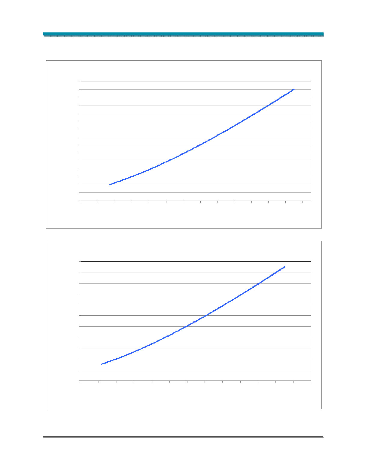
The Bridgelux LED Arrays are tested and binned against the specifications shown in Tables 1, 2 and 3.
Customers also have options to drive the LED Arrays at alternative drive currents dependent on the
specific application. The typical performance at any drive current can be derived from the flux vs. current
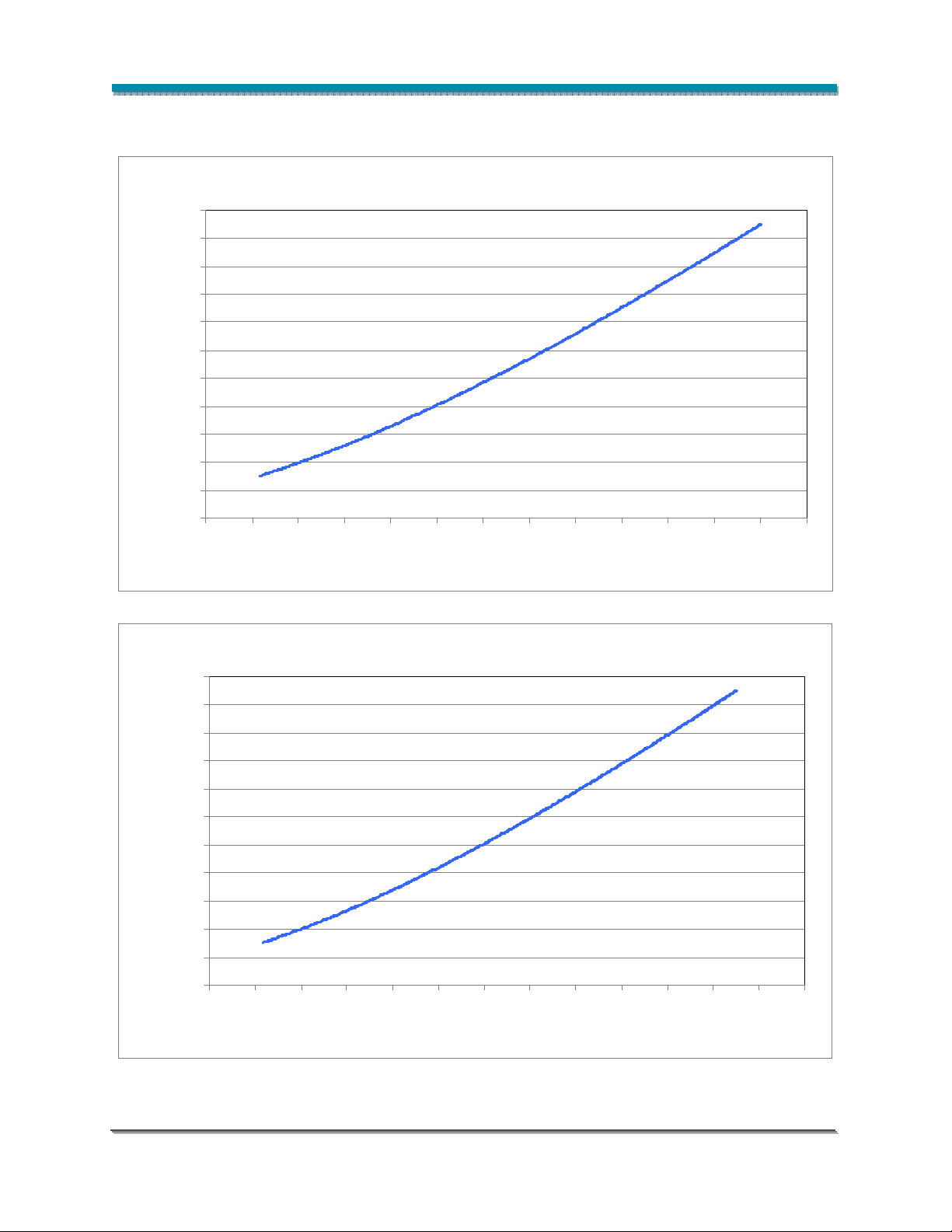
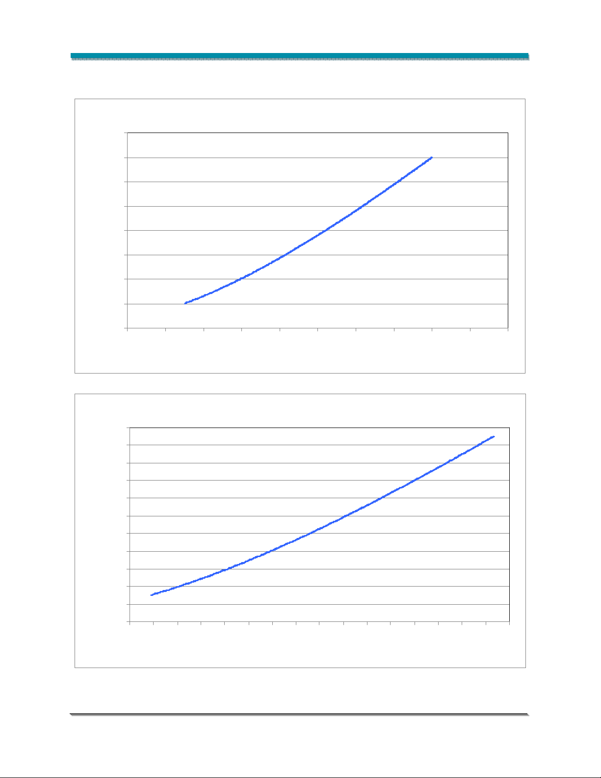
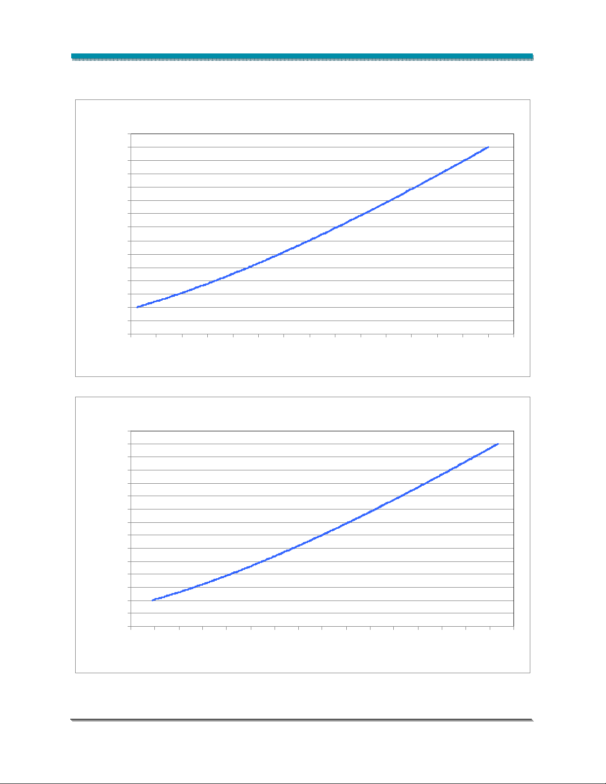
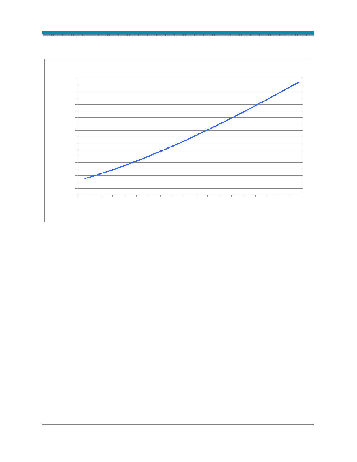
characteristics shown in Figures 8-12 and from the current vs. voltage characteristics shown in Figures
16-27. The typical performance at common drive currents is also summarized in Table 6 for warm white
products, Table 7 for neutral white products and Table 8 for cool white products.
Table 6: Typical Product Performance at Alternative Drive Currents – Warm White
Color Part Number
BXRA-W0401
BXRA-W0402
BXRA-W0403
Warm White
BXRA-W0802
Typical
Luminous
Flux фv (lm),
T
=60°C
case
Typical
Luminous Flux
фv (lm),
Tj=25°C
Typical
Forward
Voltage Vf
(V)
290 325 9.2 500
400 440 9.5 700
560 620 9.9 1050
315 350 8.8 500
420 460 9.0 700
600 660 9.5 1050
270 300 27.3 150
410 460 28.6 250
560 620 29.7 350
430 480 11.4 500
580 640 11.7 700
850 930 12.2 1050
1050 1170 12.6 1400
740 820 14.4 700
Forward
Current
[2]
(mA)
[1]
[1]
[1]
[1]
1060 1180 14.9 1050
BXRA-W1202
1200 1320 15.1 1200
1360 1510 15.4 1400
1640 1820 15.8 1750
630 700 17.1 500
860 960 17.6 700
BXRA-W1203
1230 1370 18.3 1050
1570 1750 18.9 1400
Notes for Table 6:
1. Product is tested and binned at the specified drive current.
2. Operating these LED Arrays at or below the drive currents listed in Table 6, with a case
temperature maintained at or below 70°C, will enable the average lumen maintenance projection
outlined earlier in this Product Data Sheet.
Bridgelux ES Array Series Product Data Sheet DS11 (06/23/10) Page 10 of 45
[1]
[1]
Page 11

Typical Performance at Alternative Drive Currents (continued)
Table 7: Typical Product Performance at Alternative Drive Currents – Neutral White
Color Part Number
BXRA-N0402
BXRA-N0802
Neutral White
BXRA-N1203
Typical
Luminous
Flux фv (lm),
T
=60°C
case
Typical
Luminous Flux
фv (lm),
Tj=25°C
Typical
Forward
Voltage Vf
(V)
Forward
Current
[2]
(mA)
330 370 8.8 500
400 440 8.9 600
[1]
450 500 9.0 700
470 525 11.4 500
640 710 11.7 700
920 1020 12.2 1050
[1]
1170 1300 12.6 1400
710 790 17.1 500
960 1070 17.6 700
1380 1530 18.3 1050
[1]
1750 1950 18.9 1400
Notes for Table 7:
1. Product is tested and binned at the specified drive current.
2. Operating these LED Arrays at or below the drive currents listed in Table 7, with a case
temperature maintained at or below 70°C, will enable the average lumen maintenance projection
outlined earlier in this Product Data Sheet.
Bridgelux ES Array Series Product Data Sheet DS11 (06/23/10) Page 11 of 45
Page 12

Typical Performance at Alternative Drive Currents (continued)
Table 8: Typical Product Performance at Alternative Drive Currents – Cool White
Color Part Number
BXRA-C0402
BXRA-C0603
BXRA-C0802
Cool White
BXRA-C1202
Typical
Luminous
Flux фv
(lm),
T
=60°C
case
Typical
Luminous Flux
фv (lm),
Tj=25°C
Typical
Forward
Voltage Vf
(V)
315 340 9.2 350
410 450 9.5 500
560 620 9.9 700
360 400 27.3 150
560 620 28.6 250
750 830 29.7 350
590 650 12.2 500
800 880 12.7 700
1120 1240 13.2 1050
830 920 12.3 700
1200 1320 12.8 1050
Forward
Current
[2]
(mA)
[1]
[1]
[1]
[1]
1510 1680 13.2 1400
1020 1130 15.1 700
1460 1620 15.6 1050
BXRA-C2002
1850 2050 16.1 1400
2000 2200 16.2 1500
2270 2520 16.5 1750
Notes for Table 8:
1. Product is tested and binned at the specified drive current.
2. Operating these LED Arrays at or below the drive currents listed in Table 8, with a case
temperature maintained at or below 70°C, will enable the average lumen maintenance projection
outlined earlier in this Product Data Sheet.
Bridgelux ES Array Series Product Data Sheet DS11 (06/23/10) Page 12 of 45
[1]
Page 13
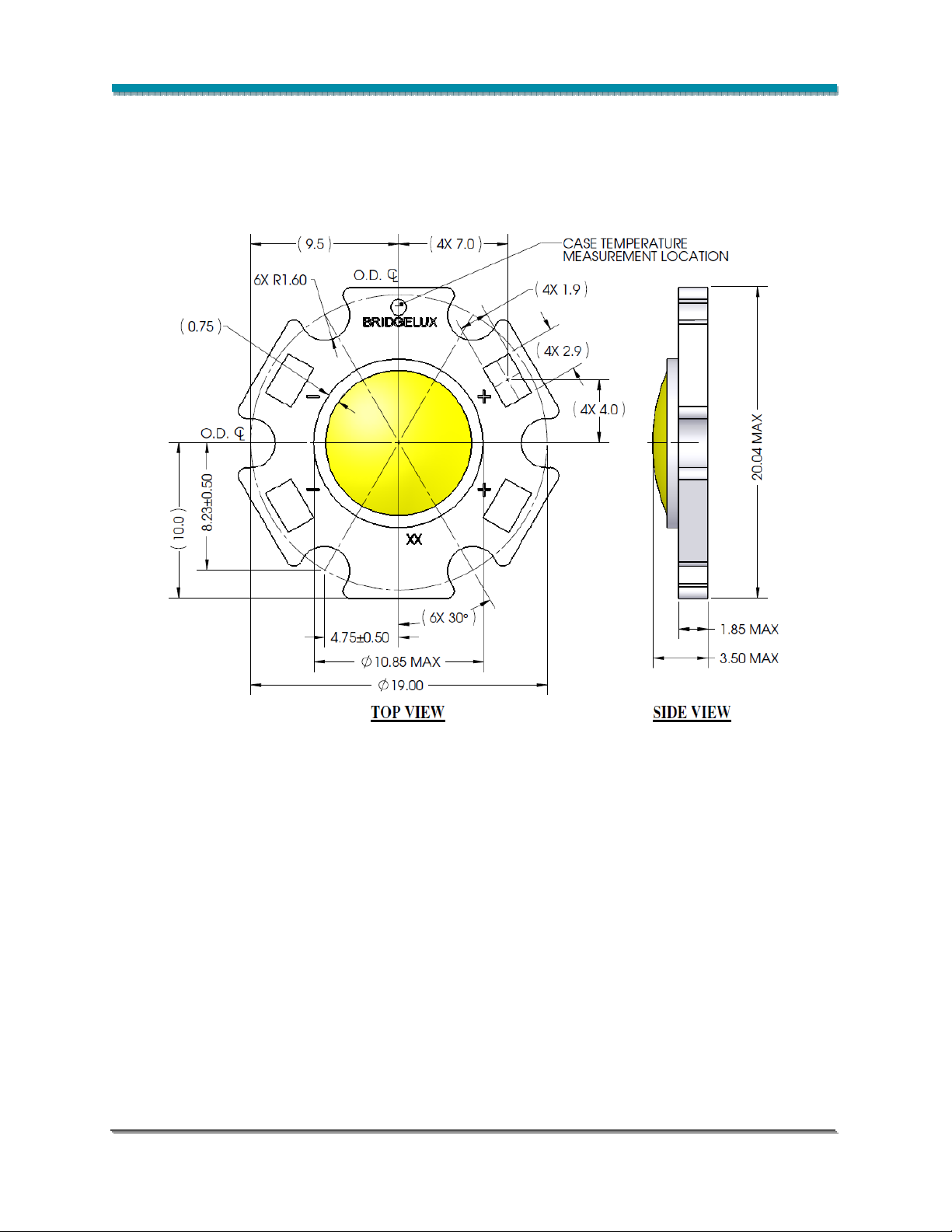
Mechanical Dimensions
Figure 1: Drawing for 400 lumen product options (part numbers BXRA-C0402, BXRA-N0402,
BXRA-W0401, BXRA-W0403, BXRA-W0402 and BXRA-C0603).
Notes for Figure 1:
1. Slots are for M2.5 or #4 screws.
2. Solder pads are labeled “+” and “-“ to denote positive and negative, respectively.
3. Drawings are not to scale.
4. Drawing dimensions are in millimeters.
5. Bridgelux recommends two tapped holes for mounting screws with 19.20 ± 0.05mm center-tocenter spacing.
6. Unless otherwise specified, tolerances are ± 0.10mm.
7. Dimensions with parentheses “( )” are for reference only.
8. Refer to product Application Notes AN10 and AN11 for product handling, mounting and heat sink
recommendations.
9. The optical center of the LED Array is defined by the mechanical center of the array.
Bridgelux ES Array Series Product Data Sheet DS11 (06/23/10) Page 13 of 45
Page 14

Mechanical Dimensions (continued)
Figure 2: Drawing for 800, 1200, and 2000 lumen product options (part numbers BXRA-C0802, BXRA-
W0802, BXRA-C1202, BXRA-W1202, BXRA-W1203, BXRA-N0802, BXRA-N1203 and BXRAC2002).
Notes for Figure 2:
1. Mounting holes are for M2.5 or #4 screws.
2. Solder pads are labeled “+” and “-“ to denote positive and negative, respectively.
3. Drawings are not to scale.
4. Drawing dimensions are in millimeters.
5. Bridgelux recommends two tapped holes for mounting screws with 26.92 ± 0.10mm center-to-center
spacing.
6. Unless otherwise specified, tolerances are ± 0.10mm.
7. Dimensions with parentheses “( )” are for reference only.
8. Refer to product Application Notes AN10 and AN11 for product handling, mounting and heat sink
recommendations.
9. The optical center of the LED Array is defined by the mechanical center of the array.
Bridgelux ES Array Series Product Data Sheet DS11 (06/23/10) Page 14 of 45
Page 15

Typical Radiation Pattern
Figure 3: Typical Spatial Radiation Pattern
Figure 4: Typical Polar Radiation Pattern
Bridgelux ES Array Series Product Data Sheet DS11 (06/23/10) Page 15 of 45
Page 16

Wavelength Characteristics at Rated Test Current, Tj=25°C
Figure 5: Typical Warm White Color Spectrum
Figure 6: Typical Neutral White Color Spectrum
Bridgelux ES Array Series Product Data Sheet DS11 (06/23/10) Page 16 of 45
Page 17

Wavelength Characteristics at Rated Test Current, Tj=25°C (continued)
Figure 7: Typical Cool White Color Spectrum
Bridgelux ES Array Series Product Data Sheet DS11 (06/23/10) Page 17 of 45
Page 18
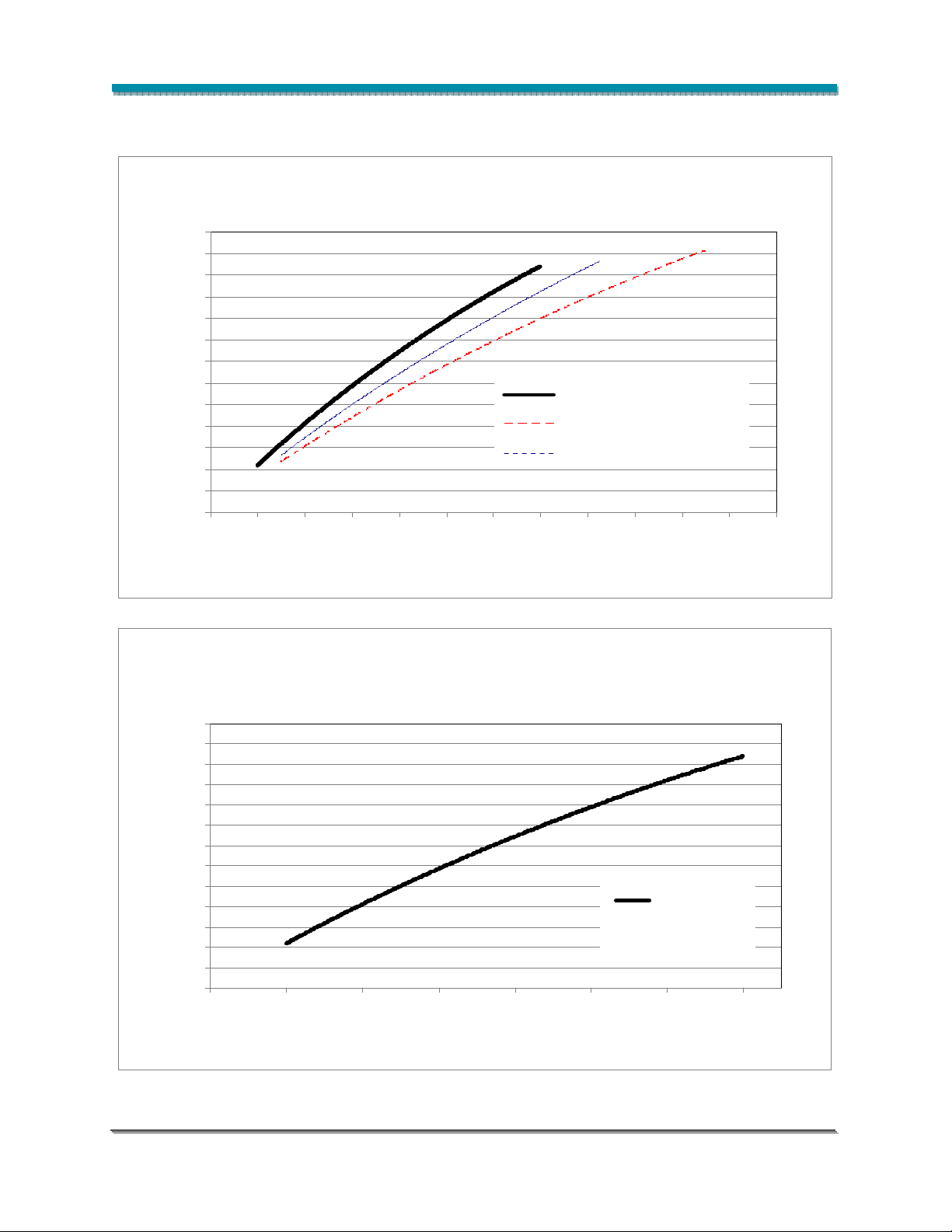
Typical Relative Luminous Flux vs. Current, Tj=25° C
Figure 8: Typical Flux vs. Current (400lm arrays)
2.60
2.40
2.20
2.00
1.80
1.60
1.40
1.20
1.00
0.80
0.60
Normalized Luminous Flux
0.40
0.20
0.00
0 200 400 600 800 1000 1200 1400 1600 1800 2000 2200 2400
BXRA-C0402
BXRA-W0401, BXRA-W0402
BXRA-N0402
Current (mA)
Figure 9: Typical Flux vs. Current
2.60
2.40
2.20
2.00
1.80
1.60
1.40
1.20
1.00
0.80
0.60
0.40
Normalized Luminous Flux
0.20
0.00
0 100 200 300 400 500 600 700
BXRA-W0403
BXRA-C0603
Current (mA)
Bridgelux ES Array Series Product Data Sheet DS11 (06/23/10) Page 18 of 45
Page 19
BXRA-W1203
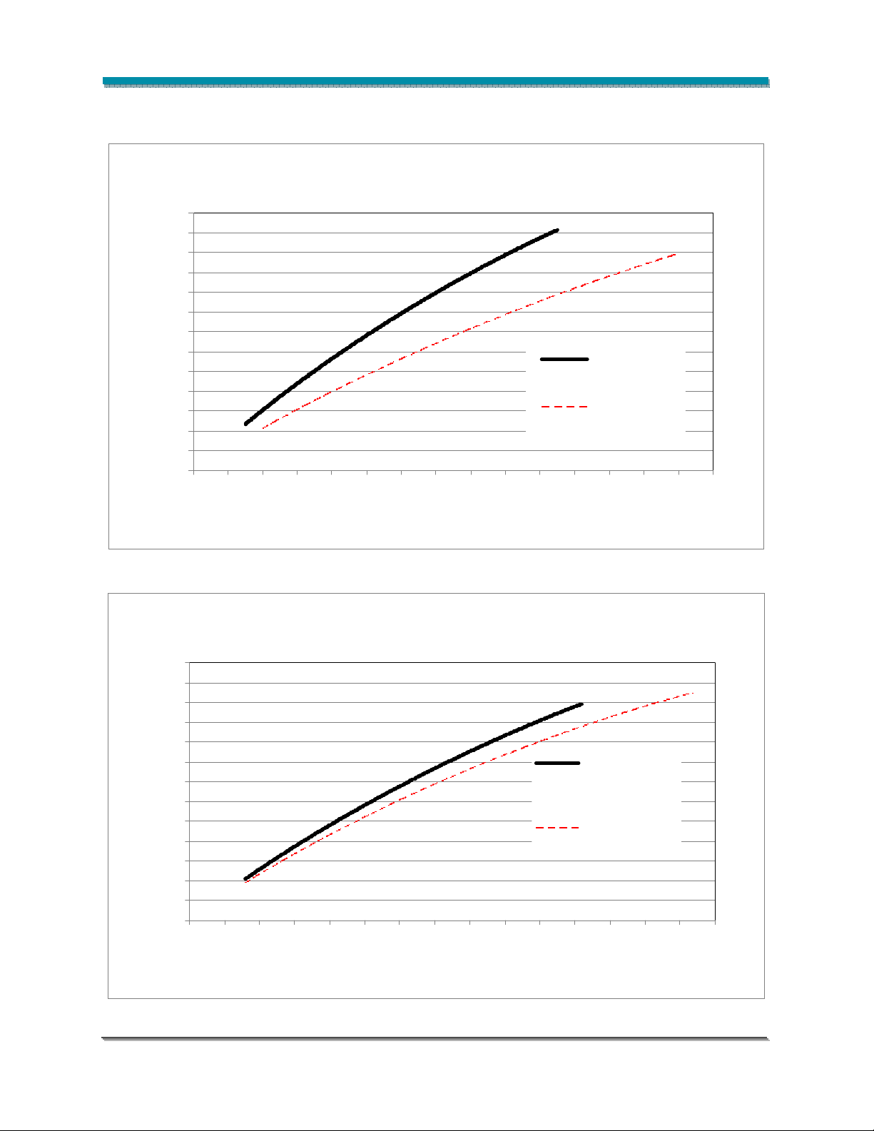
Typical Relative Luminous Flux vs. Current, Tj=25° C (continued)
Figure 10: Typical Flux vs. Current (800 lm Arrays)
2.60
2.40
2.20
2.00
1.80
1.60
1.40
1.20
1.00
0.80
0.60
Normalized Luminous Flux
0.40
0.20
0.00
0 200 400 600 800 1000 1200 1400 1600 1800 2000 2200 2400 2600 2800 3000
BXRA-C0802
BXRA-N0802,
BXRA-W0802
Current (mA)
Figure 11: Typical Flux vs. Current (1200 lm Arrays)
2.60
2.40
2.20
2.00
1.80
1.60
1.40
1.20
1.00
0.80
0.60
Normalized Luminous Flux
0.40
0.20
0.00
0 250 500 750 1000 1250 1500 1750 2000 2250 2500 2750 3000 3250 3500 3750
BXRA-C1202,
BXRA-N1203,
BXRA-W1202
Current (mA)
Bridgelux ES Array Series Product Data Sheet DS11 (06/23/10) Page 19 of 45
Page 20
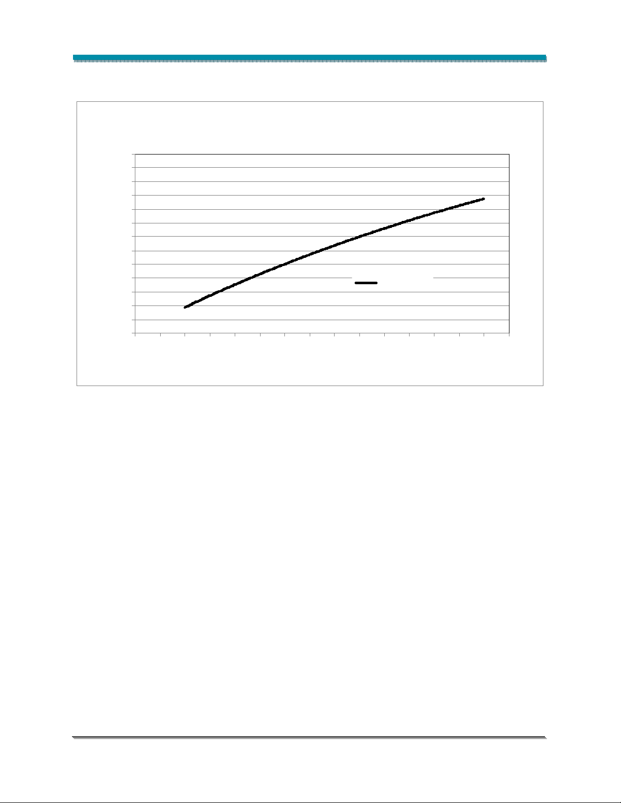
Typical Relative Luminous Flux vs. Current, Tj=25° C (continued)
Figure 12: Typical Flux vs. Current (2000 lm Arrays)
2.60
2.40
2.20
2.00
1.80
1.60
1.40
1.20
1.00
0.80
0.60
0.40
Normalized Luminous Flux
0.20
0.00
0 250 500 750 1000 1250 1500 1750 2000 2250 2500 2750 3000 3250 3500 3750
BXRA-C2002
Current (mA)
Note for Figures 8 through 12: Bridgelux does not recommend driving high power LED Arrays at low
currents. Doing so may produce unpredictable results. Pulse width modulation (PWM) is recommended
for dimming effects.
Bridgelux ES Array Series Product Data Sheet DS11 (06/23/10) Page 20 of 45
Page 21

Typical Light Output Characteristics vs. Temperature
Figure 11: Typical Flux vs. Junction Temperature
Figure 13: Typical Flux vs. Junction Temperature
1.20
1.10
1.00
0.90
0.80
0.70
0.60
0.50
Normalized Luminous Flux
0.40
0.30
Cool White
Warm White
Neutral White
0.20
-10 0 10 20 30 40 50 60 70 80
Junction Temperature, ºC
Bridgelux ES Array Series Product Data Sheet DS11 (06/23/10) Page 21 of 45
Page 22
Junction Temperature, ºC
∆x
∆y
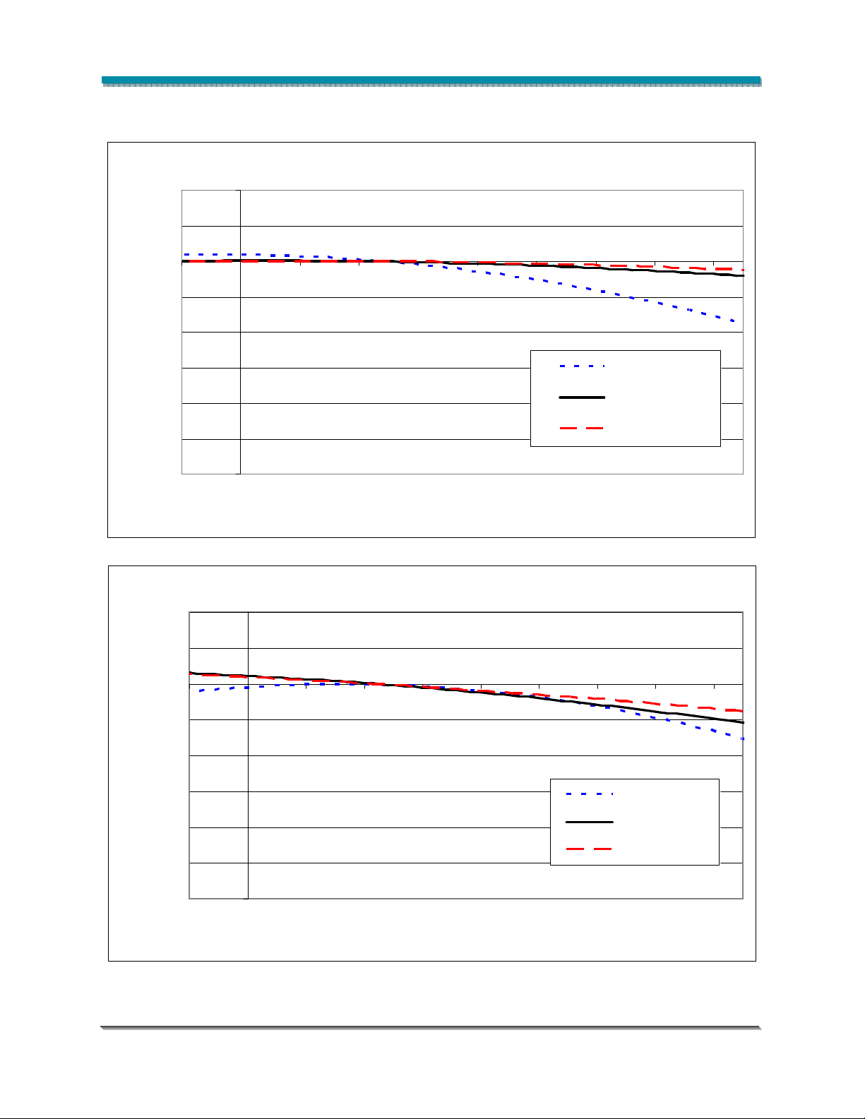
Typical Chromaticity Characteristics vs. Temperature
Figure 12: Typical x Shift vs. Junction Temperature
Figure 14: Typical x Shift vs. Junction Temperature
0.02
0.01
0.00
-0.01
-0.02
-0.03
-0.04
-0.05
-0.06
-10 0 10 20 30 40 50 60 70 80
Figure 13: Typical y Shift vs. Junction Temperature
Figure 15: Typical y Shift vs. Junction Temperature
0.02
0.01
0.00
-0.01
-0.02
Cool White
Neutral White
Warm White
-0.03
-0.04
-0.05
-0.06
Bridgelux ES Array Series Product Data Sheet DS11 (06/23/10) Page 22 of 45
Cool White
Neutral White
Warm White
-10 0 10 20 30 40 50 60 70 80
Junction Temperature, ºC
Page 23
)
Typical Forward Current Characteristics at Tj = 25°C
Figure 16: Typical Current vs. Voltage, BXRA-C0402
1500
1400
1300
1200
1100
1000
900
mA
800
700
600
500
Current (
400
300
200
100
0
8.5 8.7 8.9 9.1 9.3 9.5 9.7 9.9 10.1 10.3 10.5 10.7 10.9 11.1
Forward Voltage (V)
Figure 17: Typical Current vs. Voltage, BXRA-N0402
2200
2000
1800
1600
)
1400
mA
1200
1000
800
Current (
600
400
200
0
8.2 8.4 8.6 8.8 9.0 9.2 9.4 9.6 9.8 10.0 10.2 10.4 10.6 10.8
Forward Voltage (V)
Bridgelux ES Array Series Product Data Sheet DS11 (06/23/10) Page 23 of 45
Page 24
)
Typical Forward Current Characteristics at Tj = 25°C (continued)
Figure 18: Typical Current vs. Voltage, BXRA-W0401
2200
2000
1800
1600
1400
mA
1200
1000
800
Current (
600
400
200
0
8.6 8.8 9.0 9.2 9.4 9.6 9.8 10.0 10.2 10.4 10.6 10.8 11.0 11.2
Forward Voltage (V)
Figure 19: Typical Current vs. Voltage, BXRA-W0402
2200
2000
1800
1600
)
1400
mA
1200
1000
800
Current (
600
400
200
0
8.2 8.4 8.6 8.8 9.0 9.2 9.4 9.6 9.8 10.0 10.2 10.4 10.6 10.8
Forward Voltage (V)
Bridgelux ES Array Series Product Data Sheet DS11 (06/23/10) Page 24 of 45
Page 25
Forward Voltage
(V)
)
Typical Forward Current Characteristics at Tj = 25°C (continued)
Figure 20: Typical Current vs. Voltage, BXRA-W0403 and BXRA-C0603
800
700
600
500
400
300
200
100
0
25.0 26.0 27.0 28.0 29.0 30.0 31.0 32.0 33.0 34.0 35.0
Forward Voltage (V)
Figure 21: Typical Current vs. Voltage, BXRA-C0802
2200
2000
1800
1600
1400
mA
1200
1000
800
Current (
600
400
200
Bridgelux ES Array Series Product Data Sheet DS11 (06/23/10) Page 25 of 45
0
11.6 11.8 12.0 12.2 12.4 12.6 12.8 13.0 13.2 13.4 13.6 13.8 14.0 14.2 14.4 14.6 14.8
Page 26
Forward Voltage
(V)
)
Typical Forward Current Characteristics at Tj = 25°C (continued)
Figure 22: Typical Current vs. Voltage, BXRA-N0802 and BXRA-W0802
3000
2800
2600
2400
2200
2000
)
1800
mA
1600
1400
1200
Curre nt (
1000
800
600
400
200
0
11.2 11.4 11.6 11.8 12.0 12.2 12.4 12.6 12.8 13.0 13.2 13.4 13.6 13.8 14.0 14.2
Figure 23: Typical Current vs. Voltage, BXRA-C1202
3000
2800
2600
2400
2200
2000
1800
mA
1600
1400
1200
1000
Current (
800
600
400
200
0
11.6 11.8 12.0 12.2 12.4 12.6 12.8 13.0 13.2 13.4 13.6 13.8 14.0 14.2 14.4 14.6 14.8
Forward Voltage (V)
Bridgelux ES Array Series Product Data Sheet DS11 (06/23/10) Page 26 of 45
Page 27

Curre nt (mA)
Figure 24: Typical Current vs. Voltage, BXRA-N1203, BXRA-W1203
3200
3000
2800
2600
2400
2200
2000
1800
1600
1400
1200
1000
800
600
400
200
0
16.8 17.2 17.6 18.0 18.4 18.8 19.2 19.6 20.0 20.4 20.8 21.2
Forward Voltage (V)
Figure 25: Typical Current vs. Voltage, BXRA-W1202
3600
3400
3200
3000
2800
2600
2400
)
2200
2000
mA
1800
1600
1400
1200
Current (
1000
800
600
400
200
0
14.0 14.2 14.4 14.6 14.8 15.0 15.2 15.4 15.6 15.8 16.0 16.2 16.4 16.6 16.8 17.0 17.2 17.4 17.6
Forward Voltage (V)
Bridgelux ES Array Series Product Data Sheet DS11 (06/23/10) Page 27 of 45
Page 28
)
Typical Forward Current Characteristics at Tj = 25°C (continued)
Figure 26: Typical Current vs. Voltage, BXRA-C2002
3600
3400
3200
3000
2800
2600
2400
2200
mA
2000
1800
1600
1400
1200
Current (
1000
800
600
400
200
0
14.6 14.8 15.0 15.2 15.4 15.6 15.8 16.0 16.2 16.4 16.6 16.8 17.0 17.2 17.4 17.6 17.8 18.0 18.2 18.4
Forward Voltage (V)
Bridgelux ES Array Series Product Data Sheet DS11 (06/23/10) Page 28 of 45
Page 29
Ta - Ambient Temperature
°C
(mA)
Current Derating Curves
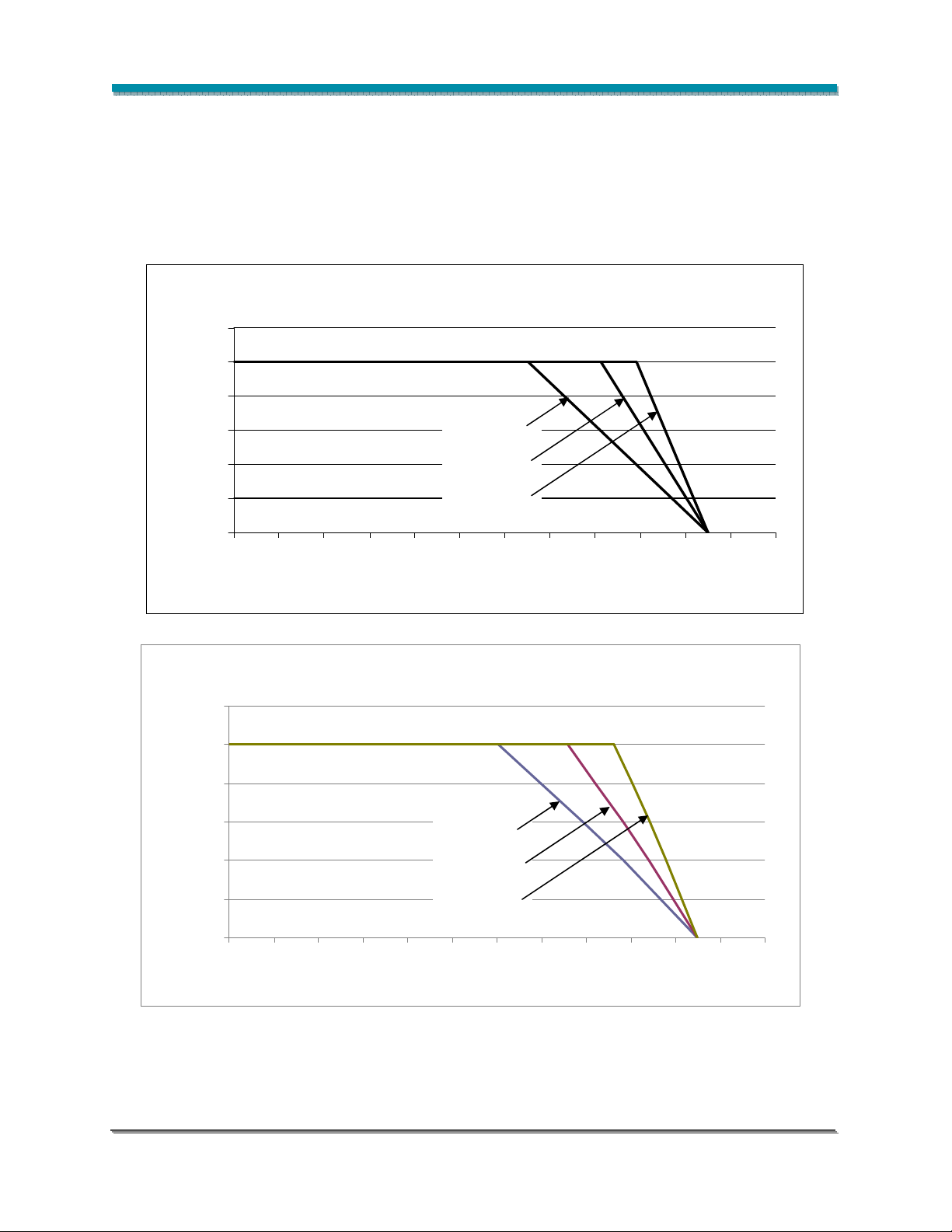
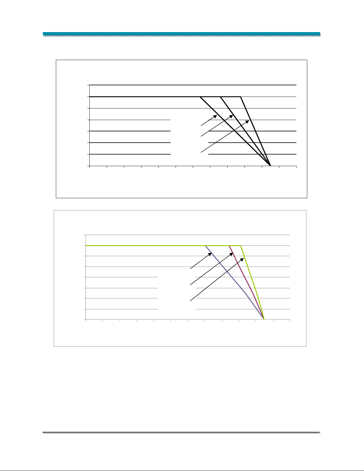
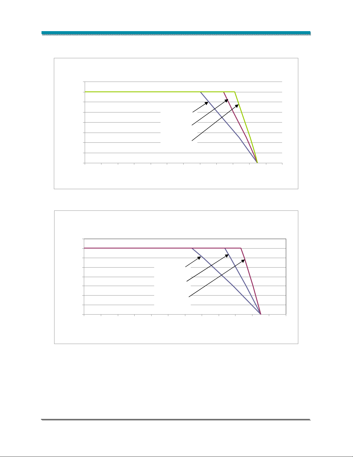
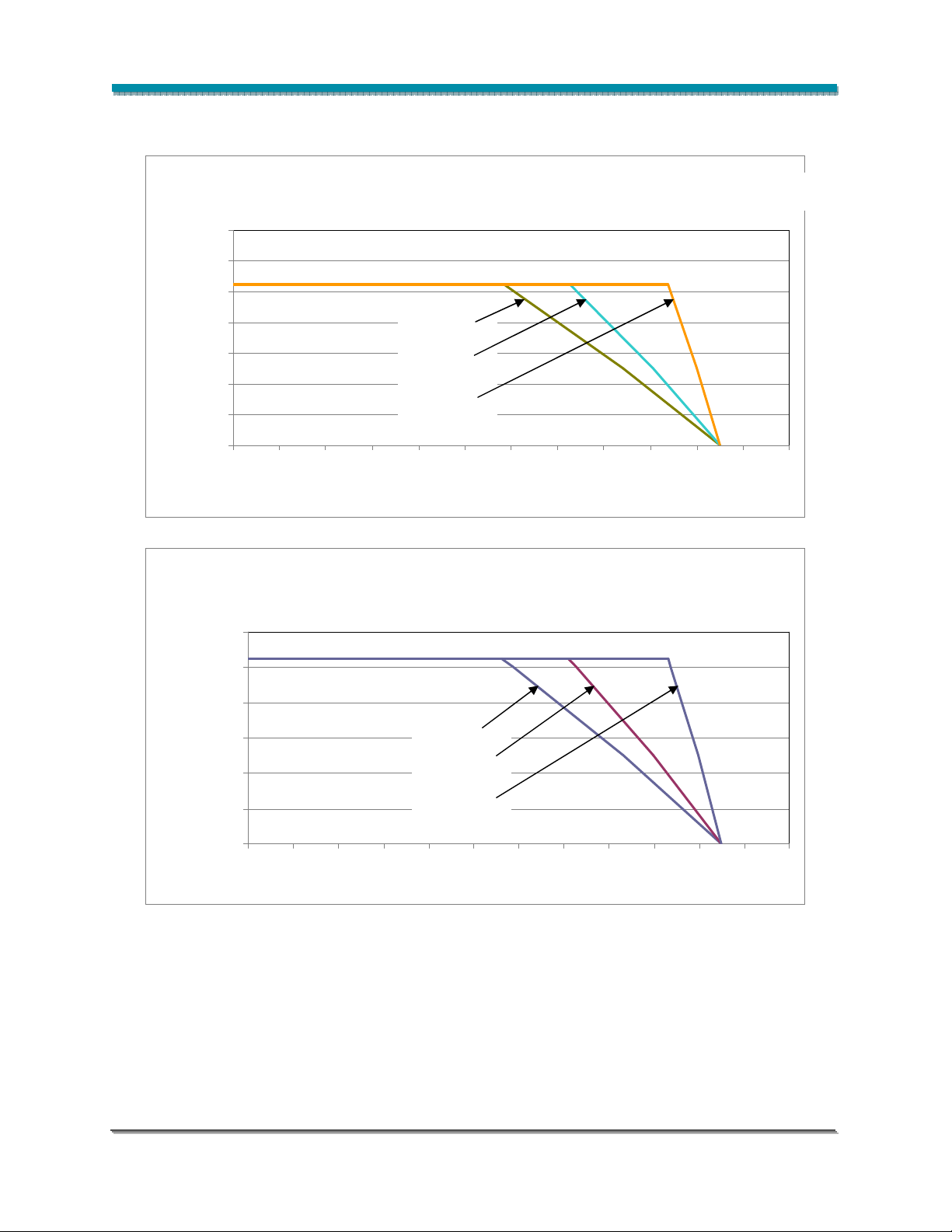
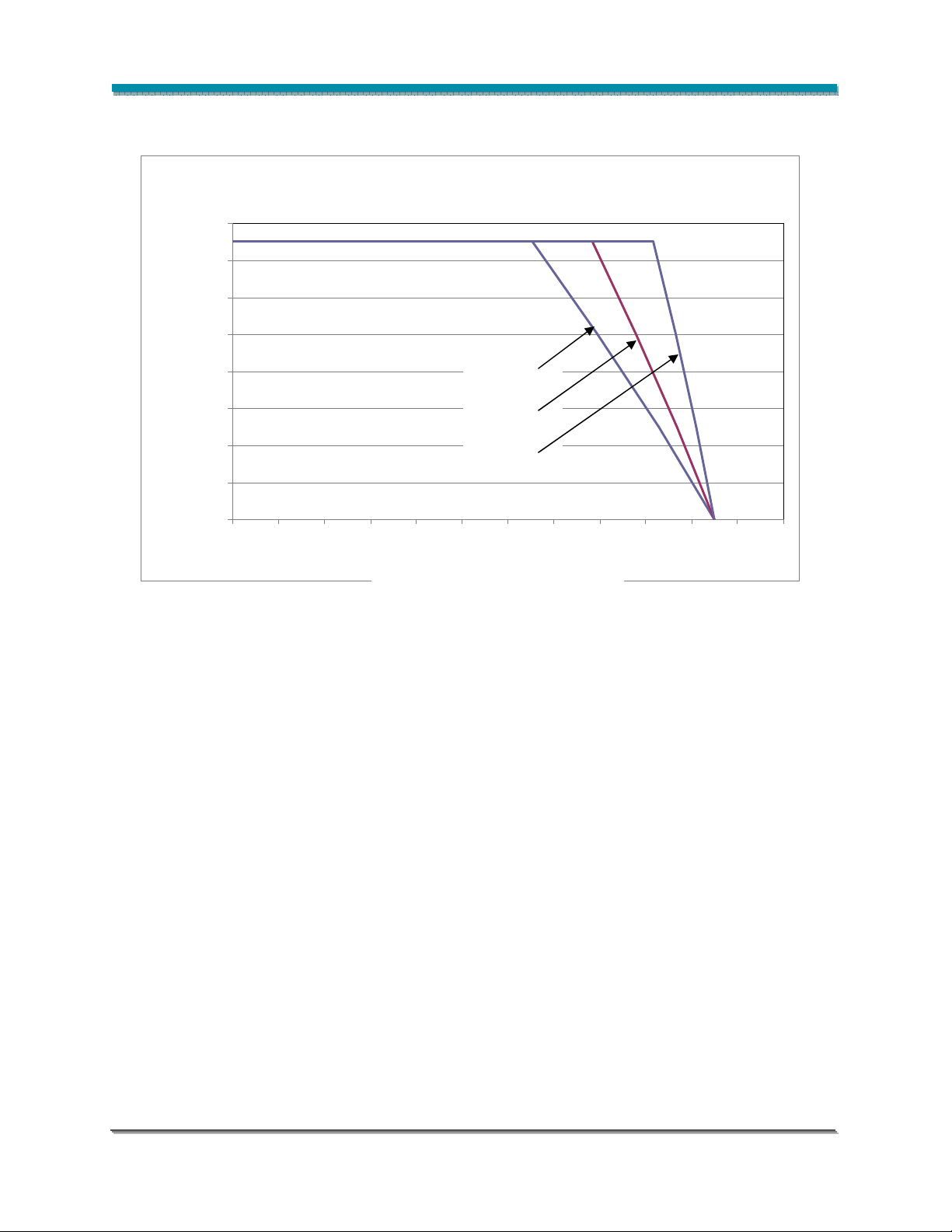
The graphs below illustrate the relationship between the system thermal resistance, drive current, and
ambient temperature. Please note that absolute maximum ratings requirements, including that of
maximum case temperature, must be adhered to in the system design. The thermal resistance values
indicated in Figures 27-37 are total system values (junction to ambient) including the thermal resistance
of the LED Array. Individual LED Array thermal resistance values are listed in Table 3.
Figure 27: Derating Curve for BXRA-W0403 and BXRA-C0603, 250mA Drive Current
300
250
200
If - Forward Current (mA)
150
100
50
10.0˚C/W
7.0˚C/W
5.0˚C/W
0
0 10 20 30 40 50 60 70 80 90 100 110 120
Ta - Ambient Temperature, C
Figure 28: Derating Curve for BXRA-C0402, 500mA Drive Current
600
500
400
300
200
10.0˚C/W
7.0˚C/W
If - Forward Current
Bridgelux ES Array Series Product Data Sheet DS11 (06/23/10) Page 29 of 45
100
0
0 10 20 30 40 50 60 70 80 90 100 110 120
5.0˚C/W
Page 30
Current Derating Curves (continued)
Figure 29: Derating Curve for BXRA-N0402, 600mA Drive Current
700
600
500
400
8.0˚C/W
300
200
6.0˚C/W
If - Forward Current (mA)
100
4.0˚C/W
0
0 10 20 30 40 50 60 70 80 90 100 110 120
Ta - Ambient Temperature, C
Figure 30: Derating Curve for BXRA-W0401, 700mA Drive Current
800
700
600
500
400
300
200
If - Forward Current (mA)
100
6.0˚C/W
4.0˚C/W
3.0˚C/W
0
0 10 20 30 40 50 60 70 80 90 100 110 120
Ta - Ambient Temperature ° C
Bridgelux ES Array Series Product Data Sheet DS11 (06/23/10) Page 30 of 45
Page 31
Current Derating Curves (continued)
Figure 31: Derating Curve for BXRA-W0402, 700mA Drive Current
800
700
600
500
400
300
200
If - Forward Current (mA)
100
0
0 10 2 0 30 40 50 60 70 80 90 100 110 120
6.0˚C/W
4.0˚C/W
3.0˚C/W
Ta - Ambient Temperature ° C
Figure 32: Derating Curve for BXRA-C0802, 700mA Drive Current
800
700
600
500
400
300
200
If - Forward Current (mA)
100
0
0 10 20 30 40 50 60 70 80 90 100 110 120
5.0˚C/W
3.0˚C/W
2.0˚C/W
Ta - Ambient Temperature o C
Bridgelux ES Array Series Product Data Sheet DS11 (06/23/10) Page 31 of 45
Page 32
Ta - Ambient Temperature °C
Ta - Ambient Temperature °C
Current Derating Curves (continued)
Figure 33: Derating Curve for BXRA-W0802, BXRA-N0802, 1050mA Drive Current
1400
1200
1000
800
600
400
200
If - Forward Current (mA)
0
0 10 20 30 40 50 60 70 80 90 100 110 120
4.0˚C/W
3.0˚C/W
1.5˚C/W
Figure 34: Derating Curve for BXRA-C1202, 1050 mA Drive Current
1200
1000
800
600
400
4.0˚C/W
3.0˚C/W
If - Forward Current (mA)
Bridgelux ES Array Series Product Data Sheet DS11 (06/23/10) Page 32 of 45
200
0
0 10 20 30 40 50 60 70 80 90 100 110 120
1.5˚C/W
Page 33

Ta - Ambient Temperature ° C
(mA)
Current Derating Curves (continued)
Figure 35: Derating Curve for BXRA-N1203 and BXRA-W1203, 1050 mA Drive Current
1200
1000
If - Forward Current (mA)
If - Forward Current
800
600
400
2.0˚C/W
1.5˚C/W
1.0˚C/W
200
0
0 10 20 30 40 50 60 70 80 90 100 110 120
Ta - Ambient Temperature, C
Figure 36: Derating Curve for BXRA-W1202, 1200 mA Drive Current
1400
1200
1000
800
600
400
200
0
0 10 20 30 40 50 60 70 80 90 100 110 120
2.0˚C/W
1.5˚C/W
1.0˚C/W
Bridgelux ES Array Series Product Data Sheet DS11 (06/23/10) Page 33 of 45
Page 34
If - Forward Current
(mA)
Ta –
Ambient Temperature °C
Current Derating Curves (continued)
Figure 37: Derating Curve for BXRA-C2002, 1500 mA Drive Current
1600
1400
1200
1000
800
600
400
200
0
0 10 20 30 40 50 60 70 80 90 100 110 120
2.0˚C/W
1.5˚C/W
1.0˚C/W
Bridgelux ES Array Series Product Data Sheet DS11 (06/23/10) Page 34 of 45
Page 35

Product Binning
Typical manufacturing processes of semiconductor products result in a variation in performance
surrounding the typical data sheet values. In order to minimize variation in the end product or application,
Bridgelux bins its LED Arrays for luminous flux and color.
Bridgelux LED Arrays are labeled using a 4-digit alphanumeric bin code. This bin code is printed on the
back of each LED Array in the following format:
A B C D
Where:
A – designates flux bin (P, Q, R etc.)
B C – designates color bin (P3, P4, Q3, etc.)
D – reserved for future product designations.
All product packaged within a single tube are of the same flux and color bin combination (or bin code).
Using these codes it is possible to determine the best product utilization to deliver the consistency
required in a given application.
Luminous Flux Binning Information
The table below lists the standard photometric luminous flux bins for Bridgelux LED Arrays (tested and
binned at the indicated test current). Although several bins are outlined, product availability in a particular
bin varies by product and production run. Please contact your Bridgelux sales representative for further
information regarding product availability. All production testing and binning (both flux and color binning)
is conducted under pulsed test conditions at Tj = 25°C.
Table 9: Luminous Flux Bins
Bin
Code
C 360 lm 400 lm
D 400 lm 440 lm L 880 lm 1020 lm T 1740 lm 2000 lm
E 440 lm 500 lm M 1020 lm 1090 lm U 2000 lm 2200 lm
F 500 lm 560 lm N 1090 lm 1200 lm V 2200 lm 2450 lm
G 560 lm 620 lm
J 720 lm 800 lm R 1380 lm 1530 lm
Min Max
Bin
Code
K 800 lm 880 lm
P 1200 lm 1320 lm
Min Max
Bin
Code
S 1530 lm 1740 lm
W 2450 lm 2700 lm
Min Max
H 620 lm 720 lm Q 1320 lm 1380 lm X 2700 lm 3000 lm
Bridgelux ES Array Series Product Data Sheet DS11 (06/23/10) Page 35 of 45
Page 36
N3
P3
Q3
N3
P3
Q3
N3
P3
Q3
N3
P3
Q3
N3
P3
Q3
N3
P3
Q3
N3
P3
Q3
N3
P3
Q3
Color Binning Information
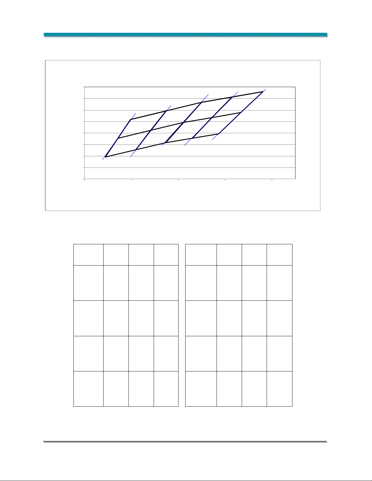
Figure 38: Graph of Warm White Test Bins in xy Color Space
0.43
0.43
0.43
0.43
0.43
0.43
0.43
0.43
0.42
0.42
0.42
0.42
0.42
0.42
0.42
0.42
0.41
0.41
0.41
0.41
0.41
0.41
0.41
0.41
0.40
0.40
0.40
0.40
0.40
0.40
0.40
0.40
Y
Y
Y
Y
Y
Y
Y
Y
0.39
0.39
0.39
0.39
0.39
0.39
0.39
0.39
0.38
0.38
0.38
0.38
0.38
0.38
0.38
0.38
0.37
0.37
0.37
0.37
0.37
0.37
0.37
0.37
K
K
0.36
0.36
0.36
0.36
0.36
0.36
0.36
0.36
0.35
0.35
0.35
0.35
0.35
0.35
0.35
0.35
0.38 0.40 0.42 0.44 0.46
0.38 0.40 0.42 0.44 0.46
0.38 0.40 0.42 0.44 0.46
0.38 0.40 0.42 0.44 0.46
0.38 0.40 0.42 0.44 0.46
0.38 0.40 0.42 0.44 0.46
0.38 0.40 0.42 0.44 0.46
0.38 0.40 0.42 0.44 0.46
0
0
1
1
7
7
3
3
N4
N4
N4
N4
N4
N4
R4
R4
R4
R4
R4
Q4
Q4
Q4
Q4
Q4
P4
P4
P4
P4
P4
P4
N4
N4
2
K
K
5
5
6
6
4
4
3
3
2
2
2
3
3
Q4
P4
P4
K
K
K
K
K
K
K
K
4
0
0
3
3
3
3
3
3
4
5
5
5
5
5
5
0
0
3
3
4
4
4
4
4
4
0
0
0
0
0
0
R4
Q4
Q4
K
K
5
5
X
X
X
X
X
X
R3
R3
R3
R3
R3
R3
R3
R3
R4
R4
K
K
0
0
7
7
8
8
2
2
X
X
Table 10: Warm White xy Bin Coordinates and Associated Typical CCT
Bin
Code
N3
N4
P3
0.4223 0.3990
P4
X Y
0.3943 0.3853
0.3996 0.4015
0.4148 0.4090
0.4083 0.3921
0.3889 0.3690
0.3943 0.3853
0.4083 0.3921
0.4018 0.3752
0.4083 0.3921
0.4148 0.4090
0.4299 0.4165
0.4018 0.3752
0.4083 0.3921
0.4223 0.3990
0.4147 0.3814
ANSI
CCT
(K)
3500
3500
3500
0.4468 0.4077
3500
0.4373 0.3893
Bin
Code
0.4299 0.4165
Q3
0.4431 0.4213
0.4345 0.4033
0.4223 0.3990
Q4
0.4345 0.4033
0.4260 0.3854
0.4431 0.4213
R3
0.4562 0.4260
R4
0.4345 0.4033
0.4468 0.4077
X Y
0.4223 0.3990
0.4147 0.3814
0.4345 0.4033
0.4260 0.3854
ANSI
CCT
(K)
3000
3000
3000
3000
Bridgelux ES Array Series Product Data Sheet DS11 (06/23/10) Page 36 of 45
Page 37
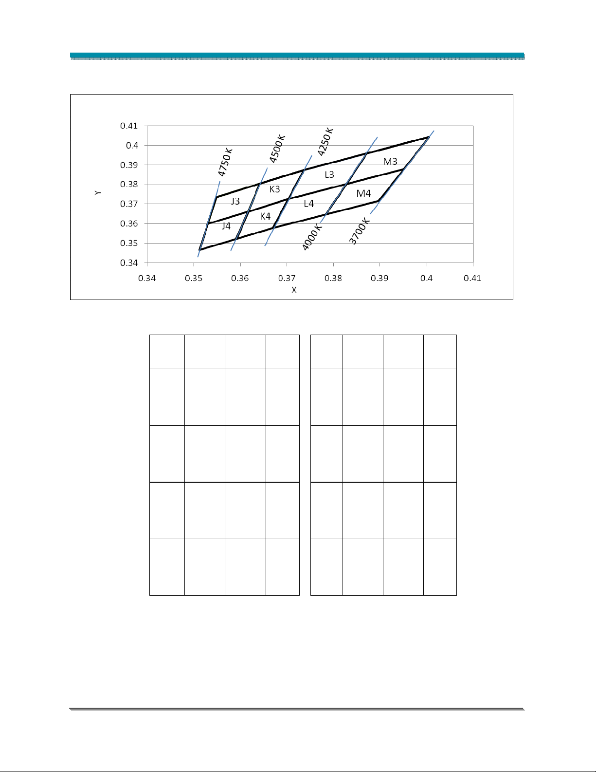
Color Binning Information (continued)
Figure 39: Graph of Neutral White Test Bins in xy Color Space
Table 11: Neutral White xy Bin Coordinates and Associated Typical CCT
Bin X Y
0.3530 0.3601
0.3548 0.3736
J3
0.3642 0.3805
0.3617 0.3663
0.3512 0.3465
0.3530 0.3601
J4
0.3617 0.3663
0.3591 0.3522
0.3617 0.3663
0.3642 0.3805
K3
0.3736 0.3874
0.3703 0.3726
0.3591 0.3522
0.3617 0.3663
K4
0.3703 0.3726
0.3670 0.3578
ANSI
CCT
(K)
4500
4500
4500
4500
Bin X Y
0.3703 0.3726
0.3736 0.3874
L3
0.3871 0.3959
0.3670 0.3578
0.3703 0.3726
0.3828 0.3803
0.3828 0.3803
0.3871 0.3959
0.4006 0.4044
0.3784 0.3647
0.3828 0.3803
0.3952 0.3880
0.3828 0.3803
L4
0.3784 0.3647
M3
0.3952 0.3880
M4
0.3898 0.3716
ANSI
CCT
(K)
4000
4000
4000
4000
Bridgelux ES Array Series Product Data Sheet DS11 (06/23/10) Page 37 of 45
Page 38
H4
C3
D3
H4
C3
D3
Color Binning Information (continued)
0.38
0.38
0.37
0.37
0.36
0.36
0.35
0.35
Y
Y
0.34
0.34
0.33
0.33
0.32
0.32
0.31
0.31
0.30 0.31 0.32 0.33 0.34 0.35 0.36
0.30 0.31 0.32 0.33 0.34 0.35 0.36
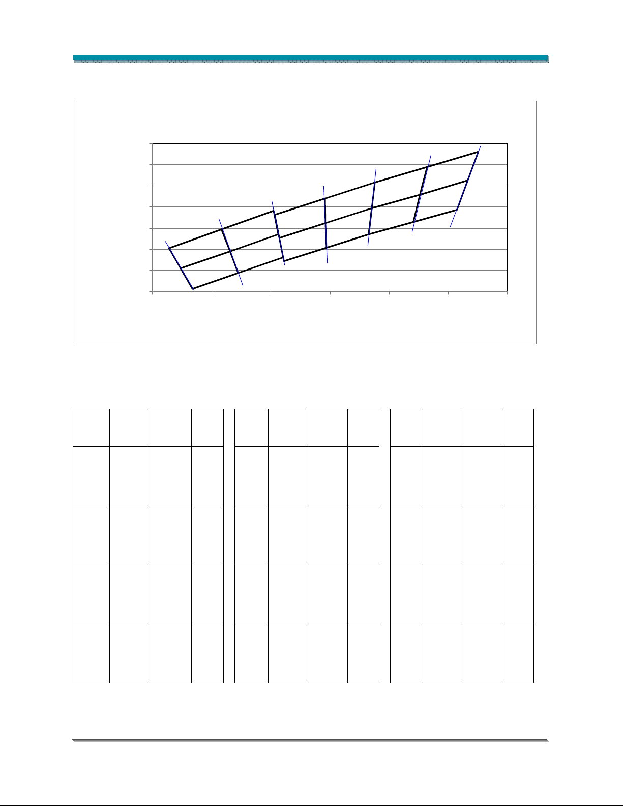
Figure 40: Graph of Cool White Test Bins in xy Color Space
K
K
0
0
3
3
5
5
6
C4
C4
6
K
K
0
0
4
4
0
0
7
7
D4
D4
K
K
0
0
2
2
0
0
6
6
E4
E4
E3
E3
5665 K
5665 K
G3
G3
F3
F3
G4
G4
F4
F4
8
K
K
0
0
1
1
3
3
5
5
X
X
8
2
2
0
0
5
5
H3
H3
K
K
K
K
5
5
4
4
7
7
4
4
Code
Bin
C3
C4
D3
D4
Table 12: Cool White xy Bin Coordinates and Associated Typical CCT
ANSI
X Y
CCT
(K)
0.3048 0.3209
0.3131 0.3290 0.3293 0.3423 0.3464 0.3688
0.3117 0.3393 0.3292 0.3539 0.3452 0.3558
6500
Bin
Code
E3
X Y
0.3215 0.3353
ANSI
CCT
(K)
5700
Bin
Code
G3
X Y
0.3376 0.3616
0.3028 0.3304 0.3207 0.3462 0.3371 0.3493
0.3068 0.3113
0.3145 0.3187 0.3294 0.3306 0.3452 0.3558
0.3131 0.3290 0.3293 0.3423 0.3441 0.3428
6500
0.3222 0.3243
E4
5700
0.3371 0.3493
G4
0.3048 0.3209 0.3215 0.3353 0.3366 0.3369
0.3131 0.3290
0.3213 0.3371 0.3293 0.3423 0.3551 0.3760
0.3205 0.3481 0.3371 0.3493 0.3533 0.3624
6500
0.3292 0.3539
F3
5700
0.3464 0.3688
H3
0.3117 0.3393 0.3376 0.3616 0.3452 0.3558
0.3145 0.3187
0.3221 0.3261 0.3366 0.3369 0.3533 0.3624
0.3213 0.3371 0.3371 0.3493 0.3515 0.3487
6500
0.3294 0.3306
F4
5700
0.3452 0.3558
H4
0.3131 0.3290 0.3293 0.3423 0.3441 0.3428
ANSI
CCT
(K)
5000
5000
5000
5000
Bridgelux ES Array Series Product Data Sheet DS11 (06/23/10) Page 38 of 45
Page 39
Drawing Not to Scale
Mechanical Assembly and Handling
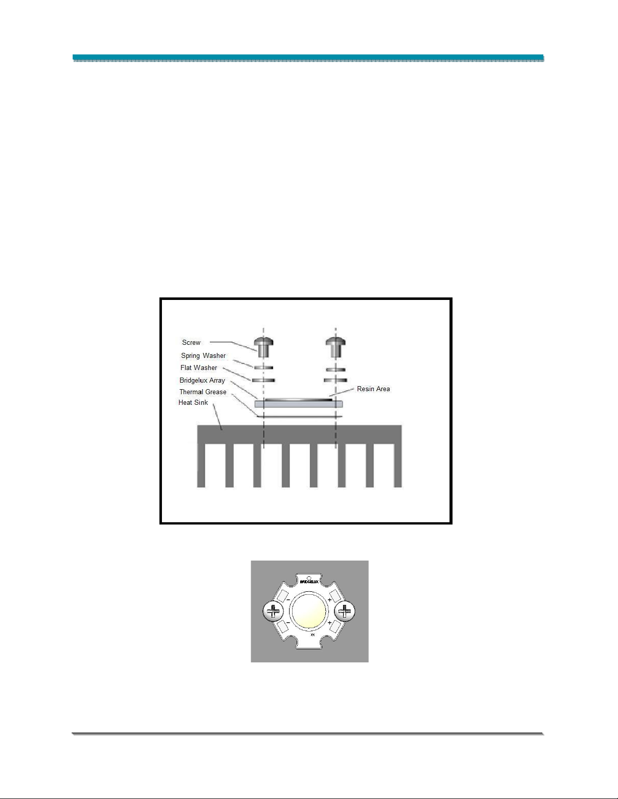
Recommended assembly is illustrated below.
When handling parts, please avoid contacting and do not apply stress to the resin area (see Figures 1
and 2, resin area is indicated in yellow).
Product should be firmly secured onto appropriate heat sink by fastening M2.5 or #4 screws on both sides
of the product as illustrated in Figure 41. The recommended center-to-center spacing for these the two
tapped holes for mounting screws is 19.20 ± 0.05mm for hexagonal star products and 26.92 ± 0.10mm for
rectangular array products. Bridgelux recommends the use of hard non-electrically conductive flat
washers with lock washers. Refer to Application Note AN11 – Handling and Assembly of Bridgelux LED
Arrays, for more details.
A thin layer of thermal grease should be applied to the bottom surface of the LED Array, between the
bottom of the array and the heat sink. All air gaps and voids between the heat sink and array should be
eliminated. Ensure that sufficient thermal grease is used to cover the entire bottom surface of the array,
but not so much that the thermal grease creeps up to the top of the array.
Figure 41: Recommended Assembly Method
For the hexagonal star products, preferred screw mounting locations are indicated in Figure 42.
Bridgelux ES Array Series Product Data Sheet DS11 (06/23/10) Page 39 of 45
Figure 42: Recommended Mounting
Locations for Hexagonal Star Products
Page 40

Product Packaging and Labeling
All Bridgelux LED Array products are 100% tested, binned and labeled. Products are labeled by printing
pertinent information on the back side of the array.
The following format is used for labeling the Bridgelux LED Arrays:
A B C D
B X R A – x x x x x
E F G H J – W W Y Y
Where:
A B C D – designates the bin code (LQ30, etc.)
x x x x x – designates the base part number (W0802, etc.)
E F G H J – designates the production lot code (12345, etc.)
W W Y Y – designates the date code (production week and production year, 0210, etc.)
Individual Bridgelux LED Arrays are packaged in tubes for shipment. All product packaged within a single
tube are of the same flux and color bin combination (or bin code). Each tube is labeled with the
information required for effective inventory management. An example of the tube label is shown in Figure
43.
Where:
Figure 43: Tube Label Example
X X X X X – designates the base part number (W0802, etc.)
A B C D – designates the bin code (LQ30, etc.)
E F G H J – designates the production lot code (12345, etc.)
W W Y Y – designates the date code (production week and production year, 0210, etc.)
Z Z – designates the quantity (25 products per tube for hexagonal stars, 20 for rectangles).
Bridgelux ES Array Series Product Data Sheet DS11 (06/23/10) Page 40 of 45
Page 41
Product Packaging and Labeling (continued)
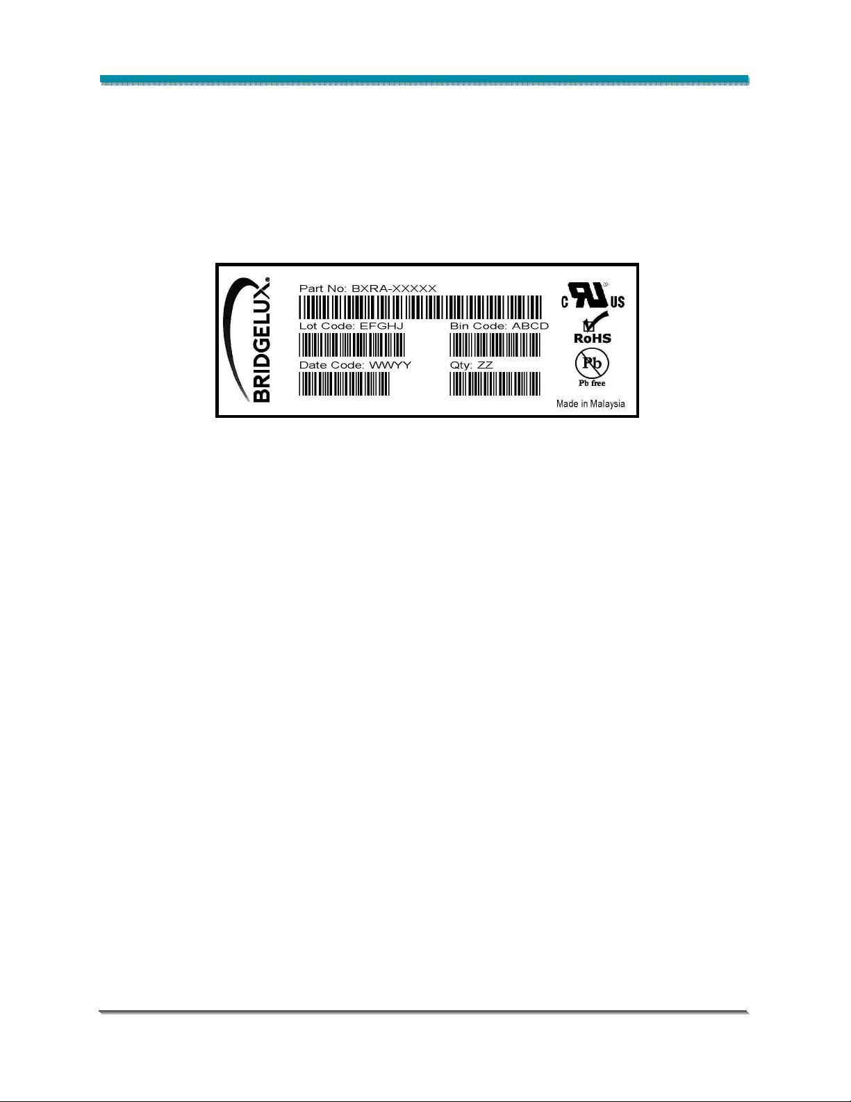
Tubes of Bridgelux LED Arrays are packaged in bags prior to loading into boxes for shipment. One tube
is loaded per bag, resulting in an SPI of 25 for hexagonal star products and 20 for rectangular product
configurations. All products packaged within a single bag are of the same flux and color bin combination
(or bin code). Each bag is labeled with the information required for effective inventory management. An
example of the bag label is shown in Figure 44.
Figure 44: Bag Label Example
Where:
X X X X X – designates the base part number (W0802, etc.)
A B C D – designates the bin code (LQ30, etc.)
E F G H J – designates product lot code
W W Y Y – designates the date code (production week and production year, 0210, etc.)
Z Z – designates the quantity (25 products per tube for hexagonal stars, 20 for rectangles).
Bags of Bridgelux LED Arrays are packaged in boxes prior to shipment. Multiple bags are packaged into
a box. All products packaged within a box are of the same base part number. Each box is labeled with
the information required for effective inventory management. An example of the box label is shown in
Figure 46.
Bridgelux ES Array Series Product Data Sheet DS11 (06/23/10) Page 41 of 45
Page 42

Product Packaging and Labeling (continued)
Figure 45: Box Label Example
Where:
X X X X X– designates the base part number (W0802, etc.)
R R R R R – used to designate product options, 00000 by default.
Q Q Q – designates the total quantity of LED Arrays contained in the box.
E F G H J – designates product lot code.
A B C D – designates the bin code (LQ30, etc.)
W W Y Y – designates the date code (production week and production year, 0210, etc.)
Z Z Z – designates the quantity per listed bin code contained in the box.
Bridgelux ES Array Series Product Data Sheet DS11 (06/23/10) Page 42 of 45
Page 43
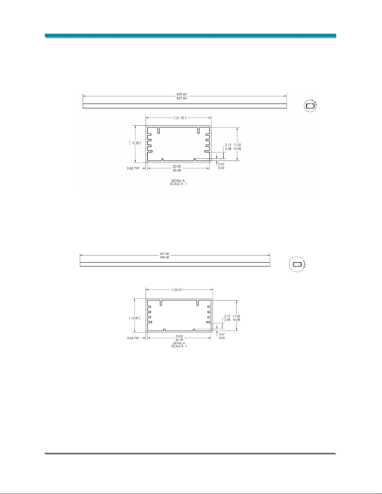
Packaging Tube Design
Figure 46: Tube Design for Hexagonal Star Products
Figure 47: Tube Design for Rectangular Array Products
Notes for Figures 46 and 47:
1. Drawings are not to scale.
2. Drawing dimensions are in millimeters.
Bridgelux ES Array Series Product Data Sheet DS11 (06/23/10) Page 43 of 45
Page 44

Design Resources
Bridgelux has developed a comprehensive set of application notes and design resources to assist
customers in successfully designing with Bridgelux LED Array products. Included below is a list of
available resources which can be downloaded from the Bridgelux web site under the Design Resources
section. These documents are updated regularly as new information becomes available, including
complimentary infrastructure products such as commercially available secondary optics and electronic
driver solutions.
Application Notes
•
AN10: Effective Thermal Management of Bridgelux LED Arrays
•
AN11: Assembly Considerations for Bridgelux LED Arrays
•
AN12: Electrical Drive Considerations for Bridgelux LED Arrays
•
AN14: Reliability Data Sheet for Bridgelux LED Arrays
•
AN15: Reflow Soldering of Bridgelux LED Arrays
•
AN16: Optical Considerations for Bridgelux LED Arrays
Optical Source Models
Optical source models and ray set files are available for all Bridgelux LED Array products, and can be
downloaded directly from the Bridgelux web site. The list below contains the formats currently available.
If you require a specific format not included in this list, please contact your Bridgelux sales representative
for assistance.
•
Zemax
•
ASAP
•
IESNA
•
LightTools
•
LucidShape
•
OPTIS SPEOS
•
PHOTOPIA
•
TracePro
•
Radiant Imaging Source Model
3D CAD Models
Three dimensional CAD models depicting the product outline of all Bridgelux LED Arrays are available in
both SAT and STEP formats. These CAD files can be downloaded directly from the Bridgelux web site.
Bridgelux ES Array Series Product Data Sheet DS11 (06/23/10) Page 44 of 45
Page 45

About Bridgelux
Bridgelux LED Arrays are developed, manufactured and marketed by Bridgelux, Inc. Bridgelux is a U.S.
lighting company and leading developer of technologies and solutions that will transform the $40 billion
global lighting industry into a $100 billion market opportunity. Based in Silicon Valley, Bridgelux is a
pioneer in solid-state lighting (SSL), expanding the market for solid state lighting by driving down the cost
of light through innovation. Bridgelux’s patented light source technology replaces traditional lighting
technologies (such as incandescent, halogen and fluorescent lamps) with integrated, solid-state solutions,
enabling lamp and luminaire manufacturers to develop high performance and energy-efficient white light
products. The plug and play simplicity of the Bridgelux LED Arrays enable our customers to address the
rapidly growing interior and exterior solid state lighting markets, including street lights, retail lighting,
commercial lighting and consumer applications. With more than 250 patent applications filed or granted
worldwide, Bridgelux is the only vertically integrated LED manufacturer that designs its solutions
specifically for the lighting industry.
For more information about the company, please visit
© 2010 Bridgelux, Inc. All rights reserved. Product specifications are subject to change without notice.
www.bridgelux.com
Bridgelux ES Array Series Product Data Sheet DS11 (06/23/10) Page 45 of 45
 Loading...