

Page 1
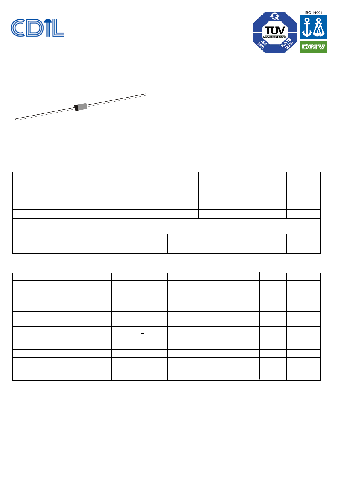
SILICON DIAC
BIDIRECTIONAL TRIGGER DIODES
DB3, DB4
GLASS PASSIVATED PNPN DEVICE
DO- 35
Functioning as a Trigger Diode with a Fixed Voltage Reference, DB3/DB4 can be
used in Conjunction with Triacs for Simplified Gate Control Circuits or as a Starting
Element in Fluorescent Lamp Ballasts
ABSOLUTE MAXIMUM RATINGS (T
a
=25ºC unless specified otherwise))
BO
O
BO
r
B
∆
1=[I
to IF=10mA]
Continental Device India Limited
An ISO/TS 16949, ISO 9001 and ISO 14001 Certified Company
Glass Axial Package
DESCRIPTION SYMBOL VALUE UNIT
Power Dissipation on Printed Circuit (L=10mm) (Ta=50oC)
Repetitive Peak on-State Current (tp=20µµs, f=100Hz)
Storage Temperature Range
Junction Temperature Range
P
I
TRM
T
tot
stg
T
j
150 mW
2 A
- 40 to +125 ºC
- 40 to +110 ºC
THERMAL RESISTANCE
Junction to Ambient in free air 400 ºC/W
Junction to Leads 150 ºC/W
R
R
th (j-a)
th (j-l)
ELECTRICAL CHARACTERISTICS (Tj=25ºC unless specified otherwise)
DESCRIPTION TEST CONDITIONS
* Breakover Voltage
SYMBOL MIN MAX UNIT
V
** C = 22nF
see diagram 1
Breakover Voltage Symmetry
[I+VBOI-I-VBOI]
DB3
DB4
** C = 22nF
28 36 V
35 45 V
+ 3 V
see diagram 1
* Dynamic Breakover Voltage
I∆V+ I
BO
5 V
see diagram 1
* Output Voltage
* Breakover Current
* Rise Time
* Leakage Current
V
I
t
I
see diagram 2
** C = 22nF
see diagram 3
VB = 0.5 VBO max
5 V
50
µA
TYP 1.5
10
µA
µs
see diagram 1
* Electrical characteristic applicable in both forward and reverse directions
** Connected in parallel with the devices.
DB3_DB4Rev_1 190402E
Continental Device India Limited
Data Sheet Page 1 of 4
Page 2
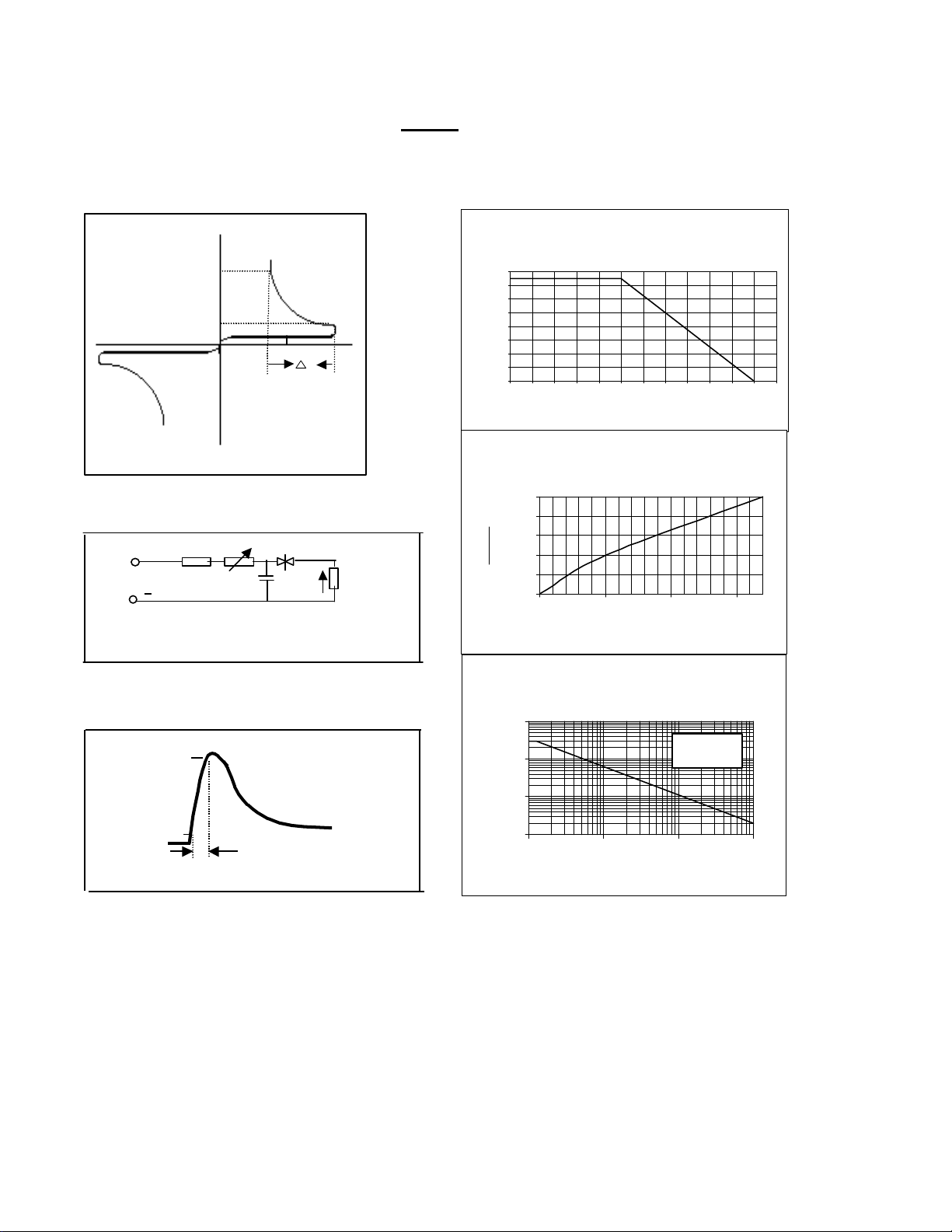
DIAGRAM 1 :Current-voltage characteristics
Power dissipation versus ambient temperature
versus junction temperature
+ IF
DB3/DB4
(maximum values)
10mA
IBO
IB
0.5 VBO
+ VV-
V
VBO
- IF
DIAGRAM 2 :Test circuit for output voltage
220V
50 HZ
10k 500k
~
0.1uF
D.U.T
R=20 ohmVO
DIAGRAM 3 : Test circuit see diagram 2.
Adjust R for Ip=0.5A
160
140
120
100
80
60
P (mW)
40
20
0
0 10 20 30 40 50 60 70 80 90 100 110 120
Tamb (o C)
Relative variation of VBO
(typical values)
1.1
1.08
C)
O
1.06
1.04
VBO(Tj)
1.02
VBO(Tj=25
1
25 50 75 100
Tj (o C)
Peak pulse current versus pulse duration (maximum
value)
10
90 %
Ip
10%
t
r
DB3_DB4Rev_1 190402E
Continental Device India Limited
F=100 HZ
Tj intial = 25 OC
(A)
TRM
I
1
0.1
0.01
10 100 1000 10000
tp (us)
Data Sheet Page 2 of 4
Page 3
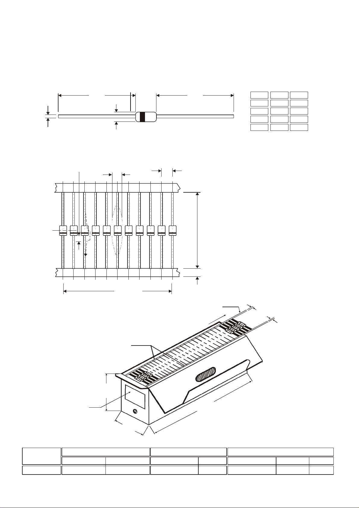
DO-35 Glass Axial Package
C
All dimensions are in mm.
300 mm (min) leader tape on every tape.
All dimensions are in mm.
.
CENTRE LINE
Packing Detail
6
±
1
DB3, DB4
DO- 35
Glass Axial Package
A B
D
NOTE:
Cathode is marked by Band.
A
DIM
A
B
C
D
MIN
25.40
3.05
0.46
1.70
MAX
—
4.15
0.56
2.29
DO-35, 52mm Taping Specification
1.5 R MAX.
1.0 5 MAX
± 1 .05
5.50
4.50
52 mm Taping Specification
T & A indicates Axial Tape and Ammo
1.
Packing (52 mm Tape Spacing).
2.
No. of empty places allowed 0.25%
3.
54.00
50.00
without consecutive empty places.
Ends of leads shall preferably not
4.
protrude beyond the tapes.
Components shall be held sufficiently in
5.
the tape or tapes so that they
can not come free in normal handling.
PACKAGE
DO-35 T&A 5K/ammo box 0.88 kg/5K pcs 10" x 3.2" x 3.2" 5K 12.7" x 12.7" x 20" 125K 25 kgs
DB3_DB4Rev_1 190402E
52.0
48.0
11 DIODES
DIODE AMMO PACK
TAPES
0
.
2
0
±
.
3
8
LABEL
±
2
8
.
0
0
.
0
STANDARD PACK INNER CARTON BOX
Details
Continental Device India Limited
Net Weight/Qty
6.0
5.0
.
.
0
LEADER
D
E
E
F
0
.
2
±
0
.
5
5
2
0
±
5
2
2
.
.
0
0
±
6
1
.
.
0
0
DO-35:- 5000 pcs./Ammo Pack
On request also available
in 26 mm Tape
OUTER CARTON BOX
Qty
Data Sheet Page 2 of 3
Qty Gr WtSize Size
Page 4

Component Disposal Instructions
or
[email protected] www.cdilsemi.com
DB3, DB4
DO- 35
1. CDIL Semiconductor Devices are RoHS compliant, customers are requested to please dispose
as per prevailing Environmental Legislation of their Country.
2. In Europe, please dispose as per EU Directive 2002/96/EC on Waste Electrical and Electronic Equipment (WEEE).
Customer Notes
Disclaimer
The product information and the selection guides facilitate selection of the CDIL's Semiconductor Device(s) best suited for application in
your product(s) as per your requirement. It is recommended that you completely review our Data Sheet(s) so as to confirm that the
Device(s) meet functionality parameters for your application. The information furnished in the Data Sheet and on the CDIL Web Site/CD
are believed to be accurate and reliable. CDIL however, does not assume responsibility for inaccuracies or incomplete information.
Furthermore, CDIL does not assume liability whatsoever, arising out of the application or use of any CDIL product; neither does it convey
any license under its patent rights nor rights of others. These products are not designed for use in life saving/support appliances
systems. CDIL customers selling these products (either as individual Discrete Semiconductor Devices or incorporated in their end
products), in any life saving/support appliances or systems or applications do so at their own risk and CDIL will not be responsible for any
damages resulting from such sale(s).
CDIL strives for continuous improvement and reserves the right to change the specifications of its products without prior notice.
CDIL is a registered Trademark of
Continental Device India Limited
C-120 Naraina Industrial Area, New Delhi 110 028, India.
Telephone + 91-11-2579 6150, 4141 1112 Fax + 91-11-2579 5290, 4141 1119
DB3_DB4Rev_1 190402E
Continental Device India Limited Data Sheet Page 3 of 3
 Loading...