

Page 1

PL CHARGING SYSTEM 8C - 1
CHARGING SYSTEM
CONTENTS
page page
GENERAL INFORMATION
OVERVIEW ............................ 1
DESCRIPTION AND OPERATION
BATTERY TEMPERATURE SENSOR ......... 2
CHARGING SYSTEM OPERATION .......... 1
ELECTRONIC VOLTAGE REGULATOR ....... 2
GENERATOR ........................... 2
DIAGNOSIS AND TESTING
BATTERY TEMPERATURE SENSOR ........ 10
CHARGING SYSTEM RESISTANCE TESTS .... 7
GENERAL INFORMATION
OVERVIEW
The battery, starting, and charging systems operate with one another, and must be tested as a complete system. In order for the vehicle to start and
charge properly, all of the components involved in
these systems must perform within specifications.
Group 8A covers the battery, Group 8B covers the
starting system, and Group 8C covers the charging
system. Refer to Group 8W - Wiring Diagrams for
complete circuit descriptions and diagrams. We have
separated these systems to make it easier to locate
the information you are seeking within this Service
Manual. However, when attempting to diagnose any
of these systems, it is important that you keep their
interdependency in mind.
The diagnostic procedures used in these groups
include the most basic conventional diagnostic methods to the more sophisticated On-Board Diagnostics
(OBD) built into the Powertrain Control Module
(PCM). Use of an induction ammeter, volt/ohmmeter,
battery charger, carbon pile rheostat (load tester),
and 12-volt test lamp may be required.
All OBD-sensed systems are monitored by the
PCM. Each monitored circuit is assigned a Diagnostic Trouble Code (DTC). The PCM will store a DTC in
electronic memory for any failure it detects. See the
On-Board Diagnostics Test in Group 8C - Charging
System for more information.
CHARGING SYSTEM ..................... 2
CURRENT OUTPUT TEST ................. 8
ON-BOARD DIAGNOSTIC SYSTEM TEST .... 10
REMOVAL AND INSTALLATION
BATTERY TEMPERATURE SENSOR ........ 12
GENERATOR .......................... 11
SPECIFICATIONS
GENERATOR RATINGS .................. 13
TORQUE SPECIFICATIONS ............... 13
DESCRIPTION AND OPERATION
CHARGING SYSTEM OPERATION
The charging system consists of:
• Generator
• Electronic Voltage Regulator (EVR) circuitry
within the Powertrain Control Module (PCM)
• Ignition switch (refer to Group 8D, Ignition Sys-
tem for information)
• Battery (refer to Group 8A, Battery for informa-
tion)
• Battery temperature sensor
• Voltmeter (refer to Group 8E, Instrument Panel
and Gauges for information)
• Wiring harness and connections (refer to Group
8W, Wiring for information)
The charging system is turned on and off with the
ignition switch. When the ignition switch is turned to
the ON position, battery voltage is applied to the
generator rotor through one of the two field terminals to produce a magnetic field. The generator is
driven by the engine through a serpentine belt and
pulley arrangement.
The amount of DC current produced by the generator is controlled by the EVR (field control) circuitry,
contained within the PCM. This circuitry is connected in series with the second rotor field terminal
and ground.
A battery temperature sensor located on the front
bumper beam is used to sense battery temperature.
This temperature data, along with data from monitored line voltage, is used by the PCM to vary the
battery charging rate. This is done by cycling the
ground path to control the strength of the rotor magnetic field. The PCM then compensates and regulates
generator current output accordingly and to maintain
Page 2
BATTERY TRAYBATTERY TEMPERATURESENSORAIR INLETTUBE
8C - 2 CHARGING SYSTEM PL
DESCRIPTION AND OPERATION (Continued)
the proper voltage depending on battery temperature.
All vehicles are equipped with On-Board Diagnostics (OBD). All OBD-sensed systems, including the
EVR (field control) circuitry, are monitored by the
PCM. Each monitored circuit is assigned a Diagnostic Trouble Code (DTC). The PCM will store a DTC in
electronic memory for any failure it detects. See OnBoard Diagnostic System Test in this group for more
information.
GENERATOR
The generator is belt-driven by the engine. It is
serviced only as a complete assembly. If the generator fails for any reason, the entire assembly must be
replaced.
As the energized rotor begins to rotate within the
generator, the spinning magnetic field induces a current into the windings of the stator coil. Once the
generator begins producing sufficient current, it also
provides the current needed to energize the rotor.
The Y type stator winding connections deliver the
induced AC current to 3 positive and 3 negative
diodes for rectification. From the diodes, rectified DC
current is delivered to the vehicle electrical system
through the generator, battery, and ground terminals.
Noise emitting from the generator may be caused
by:
• Worn, loose or defective bearings
• Loose or defective drive pulley
• Incorrect, worn, damaged or misadjusted drive
belt
• Loose mounting bolts
• Misaligned drive pulley
• Defective stator or diode
series with the generators second rotor field terminal
and its ground.
Voltage is regulated by cycling the ground path to
control the strength of the rotor magnetic field. The
EVR circuitry monitors system line voltage and battery temperature (refer to Battery Temperature Sensor for more information). It then compensates and
regulates generator current output accordingly. Also
see Charging System Operation for additional information.
DIAGNOSIS AND TESTING
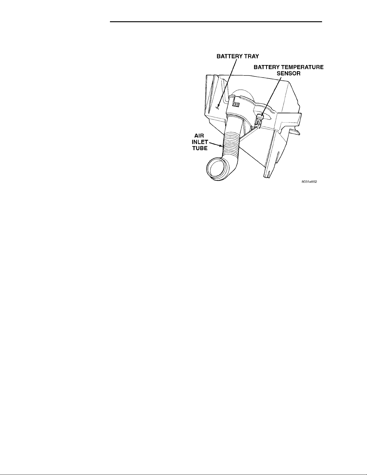
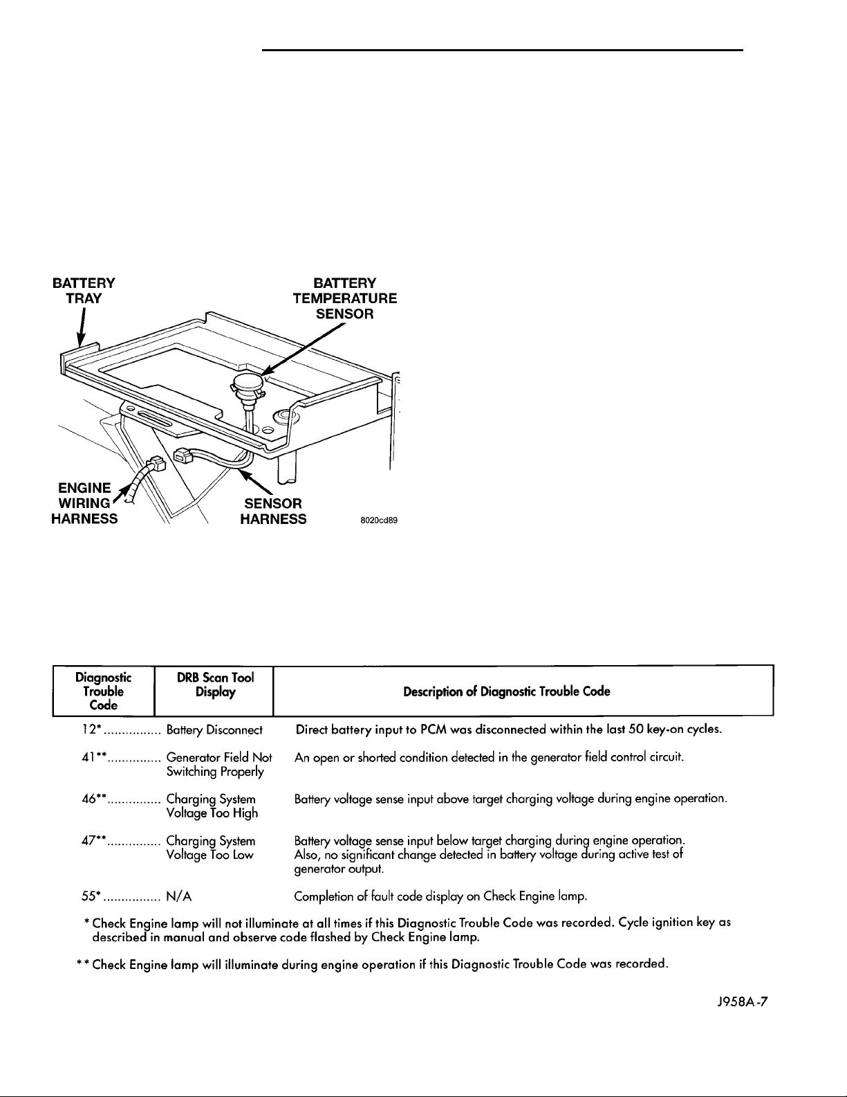
Fig. 1 Battery Temperature Sensor
BATTERY TEMPERATURE SENSOR
The battery temperature sensor is used to determine the battery temperature. This temperature
data, along with data from monitored line voltage, is
used by the PCM to vary the battery charging rate.
System voltage will be higher at colder temperatures
and is gradually reduced at warmer temperatures.
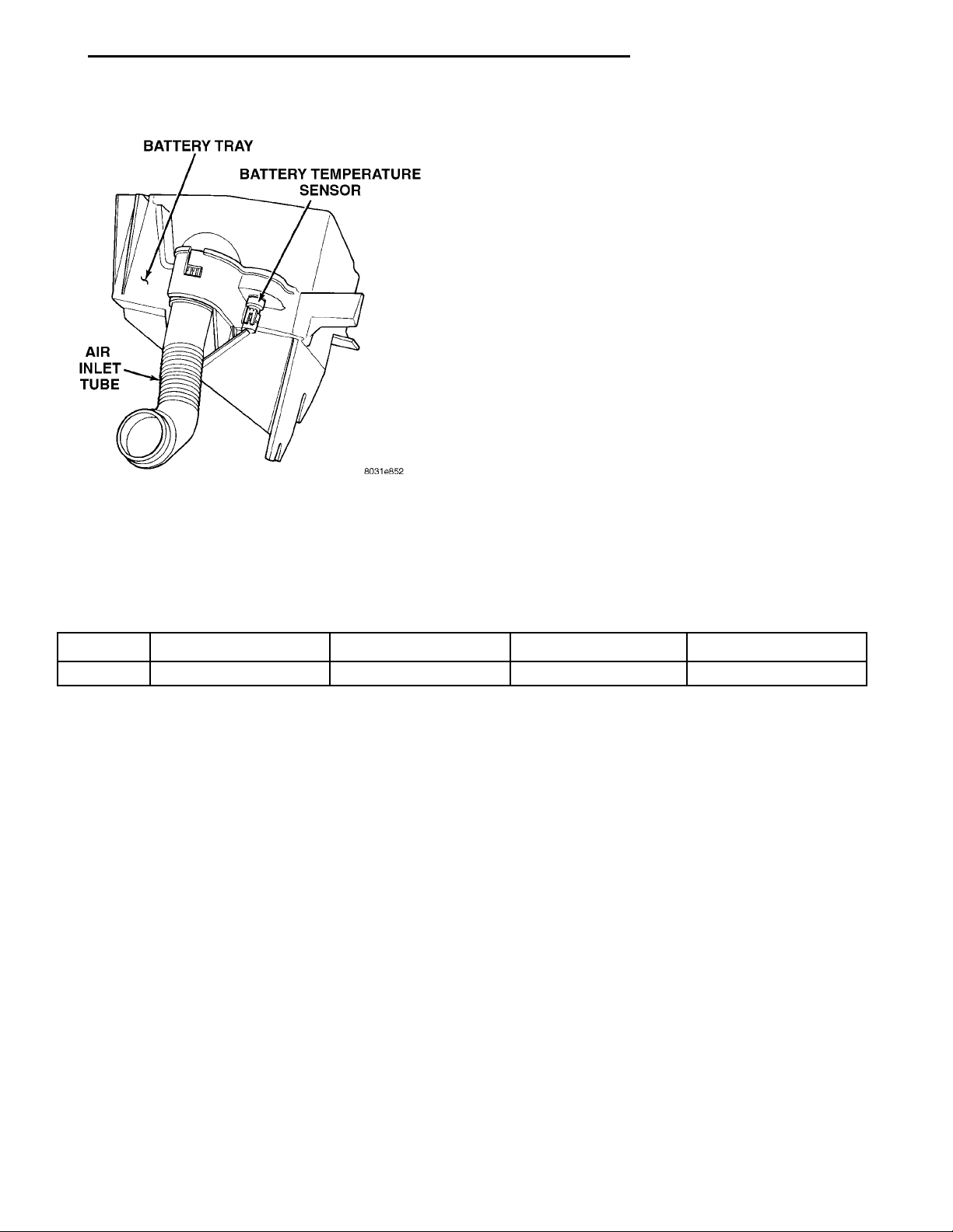
The sensor is located forward of the vehicle battery,
and is attached to the battery tray (Fig. 1).
ELECTRONIC VOLTAGE REGULATOR
The Electronic Voltage Regulator (EVR) is not a
separate component. It is actually a voltage regulating circuit located within the Powertrain Control
Module (PCM). The EVR is not serviced separately. If
replacement is necessary, the PCM must be replaced.
Operation: The amount of DC current produced
by the generator is controlled by EVR circuitry contained within the PCM. This circuitry is connected in
CHARGING SYSTEM
When the ignition switch is turned to the ON position, battery potential will register on the voltmeter.
During engine cranking a lower voltage will appear
on the meter. With the engine running, a voltage
reading higher than the first reading (ignition in ON)
should register.
The following are possible symptoms of a charging
system fault:
• The voltmeter does not operate properly
• An undercharged or overcharged battery condi-
tion occurs.
Remember that an undercharged battery is often
caused by:
• Accessories being left on with the engine not
running
• A faulty or improperly adjusted switch that
allows a lamp to stay on. See Ignition-Off Draw Test
in Group 8A, Battery for more information.
Page 3

PL CHARGING SYSTEM 8C - 3
DIAGNOSIS AND TESTING (Continued)
The following procedures may be used to correct a
problem diagnosed as a charging system fault.
INSPECTION
(1) Inspect condition of battery cable terminals,
battery posts, connections at engine block, starter
solenoid and relay. They should be clean and tight.
Repair as required.
(2) Inspect all fuses in the fuseblock module and
Power Distribution Center (PDC) for tightness in
receptacles. They should be properly installed and
tight. Repair or replace as required.
(3) Inspect the electrolyte level in the battery.
Replace battery if electrolyte level is low.
(4) Inspect generator mounting bolts for tightness.
Replace or tighten bolts if required. Refer to the Gen-
erator Removal/Installation section of this group for
torque specifications.
(5) Inspect generator drive belt condition and tension. Tighten or replace belt as required. Refer to
Belt Tension Specifications in Group 7, Cooling System.
(6) Inspect automatic belt tensioner (if equipped).
Refer to Group 7, Cooling System for information.
(7) Inspect connections at generator field, battery
output, and ground terminals. Also check ground connection at engine. They should all be clean and tight.
Repair as required.
Page 4
8C - 4 CHARGING SYSTEM PL
DIAGNOSIS AND TESTING (Continued)
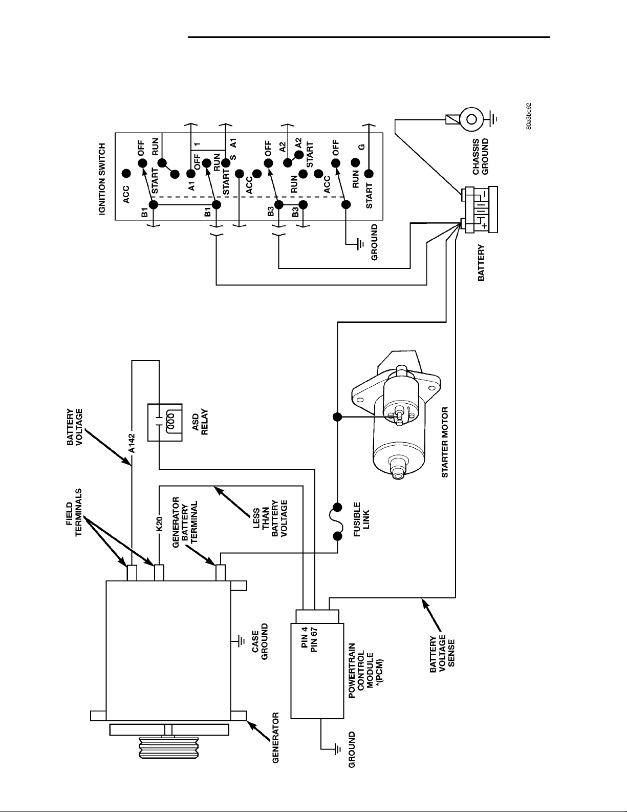
Charging System Schematic—Typical
Page 5
CHECK BATTERY CONDI-TION. CHARGE BATTERY IFNECESSARY.CHECK DRIVE BELT. REFERTO GROUP 7, COOLINGSYSTEM FOR ACCESSORYDRIVE BELTS.CHARGING SYSTEM RESIS-TANCE TESTIS GROUND PATH VOLTAGEDROP ABOVE 0.3 VOLTS?YESCLEAN MOUNTING SUR-FACESTIGHTEN FASTENERS TOSPECIFIED TORQUE.NOCHECK ON BOARD DIAG-NOSTIC TROUBLE CODES(DTC).PERFORM OUTPUT VOLT-AGE TESTYESLOW OR NO CHARGINGVOLTAGE OR DTC 41 OR47?NOREFER TO VOLTAGE DROPTEST.NOCHARGING SYSTEM ANDGENERATOR IS OK.CHARGING VOLTAGEABOVE MAXIMUM OR DTC41 OR 46? REFER TO LOADTEST VOLTAGE.YESREFER TO OVERCHARGETEST.
PL CHARGING SYSTEM 8C - 5
DIAGNOSIS AND TESTING (Continued)
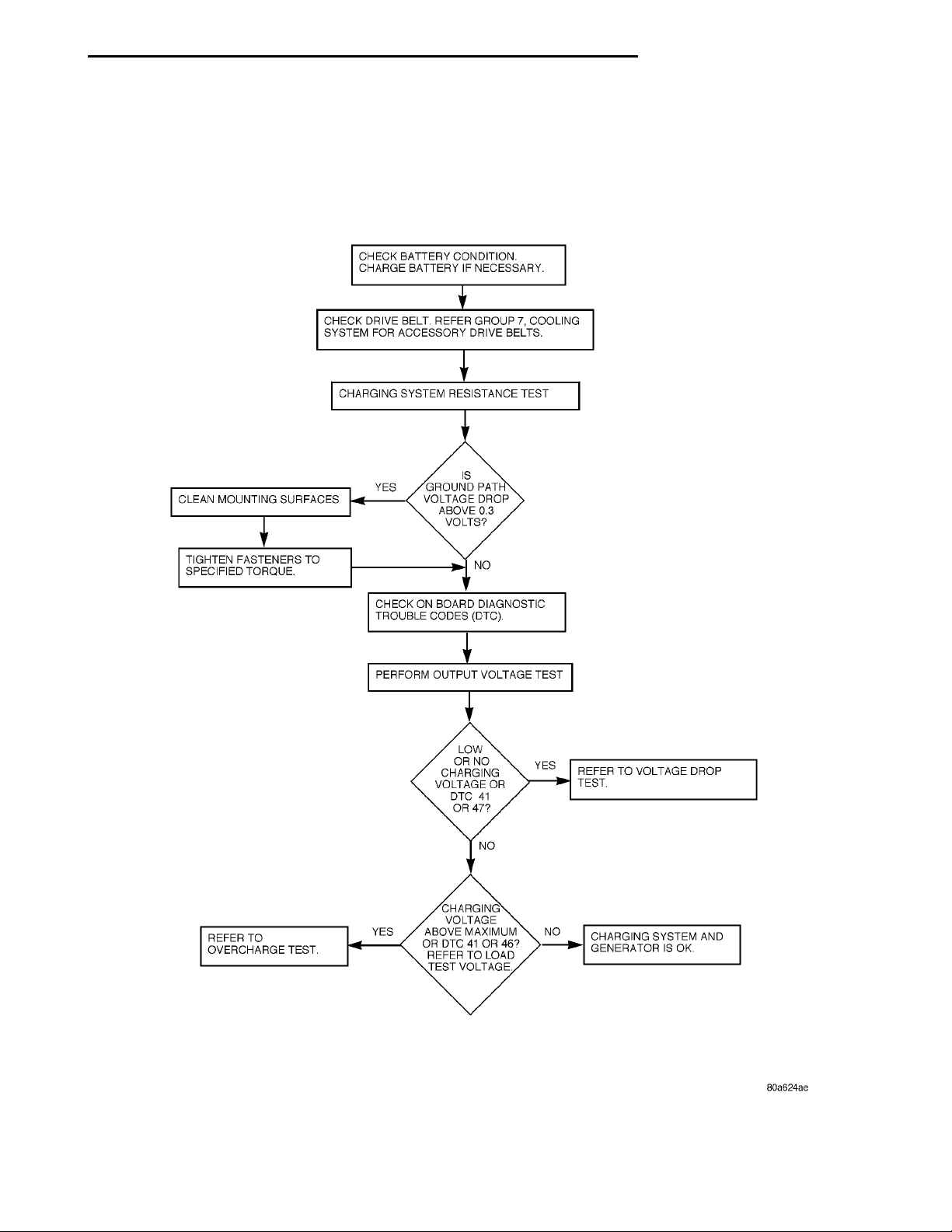
Charging System Test
Page 6
DISCONNECT BOTH 40 WAY CONNEC-TORS ON POWERTRAIN CONTROL MOD-ULE — INSPECT FOR DAMAGE ORCORROSION.REPAIR PINS YES
DAMAGED PIN ORPINS ON POWER-TRAIN MODULE?
NOREPEAT OUTPUTVOLTAGE TEST DISCONNECT FIELD TERMINAL.MEASURE RESISTANCE FROMK20 CIRCUIT ON WIRING HAR-NESS TO ENGINE GROUND.YES IS RESISTANCELESS THAN 1000OHMS? NOREPAIR SHORTTO GROUND MEASURE RESISTANCE FROMK20 TERMINAL ON GENERATORTO ENGINE GROUND.REPLACEGENERATOR YESIS RESISTANCELESS THAN 1000OHMS?NO REPEAT OUTPUTVOLTAGE TEST
8C - 6 CHARGING SYSTEM PL
DIAGNOSIS AND TESTING (Continued)
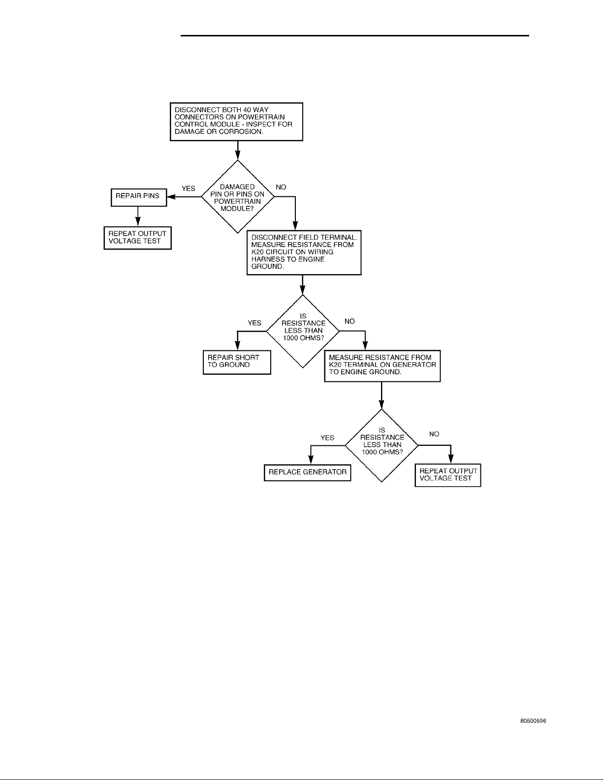
Overcharge Test
Page 7
OHMMETER WIRE HARNESS CON-NECTOR
FEEDTO POWERTRAIN CONTROLMODULEB+ TERMINALCASE GROUND
VOLTMETER
PL CHARGING SYSTEM 8C - 7
DIAGNOSIS AND TESTING (Continued)
CHARGING SYSTEM RESISTANCE TESTS
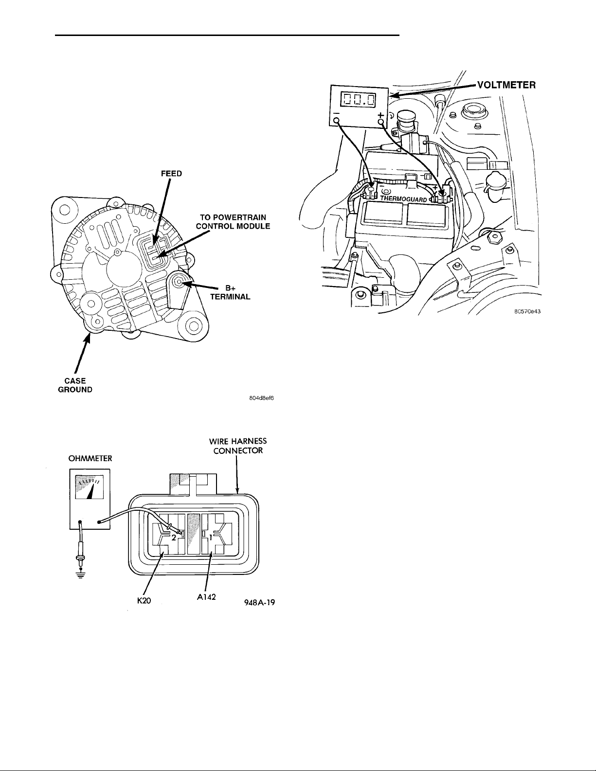
These tests will show the amount of voltage drop
across the generator output wire from the generator
output (B+) terminal to the battery positive post.
They will also show the amount of voltage drop from
the ground (-) terminal on the generator (Fig. 2) to
the battery negative post.
Fig. 2 Generator Terminals
Fig. 3 Electrical Resistance Test
A voltmeter with a 0–18 volt DC scale should be
used for these tests. By repositioning the voltmeter
test leads, the point of high resistance (voltage drop)
can easily be found.
Test points on the generator may be reached by
either removing the air cleaner housing or below by
raising the vehicle on a hoist.
Fig. 4 Battery Voltage Test
PREPARATION
(1) Before starting test, make sure battery is in
good condition and is fully-charged. See Group 8A,
Battery for more information.
(2) Check condition of battery cables at battery.
Clean if necessary.
(3) Start the engine and allow it to reach normal
operating temperature.
(4) Shut engine off.
(5) Connect an engine tachometer.
(6) Fully engage the parking brake.
TEST
(1) Start engine.
(2) Place heater blower in high position.
(3) Turn on headlamps and place in high-beam
position.
(4) Turn vehicle interior lamps on.
(5) Start engine. Bring engine speed up to 2400
rpm and hold.
(6) Testing (- ground) circuitry:
(a) Touch the negative lead of voltmeter directly
to battery positive POST (Fig. 4).
(b) Touch the positive lead of voltmeter to the
B+ output terminal stud on the generator (not the
terminal mounting nut). Voltage should be no
higher than 0.6 volts. If voltage is higher than 0.6
volts, touch test lead to terminal mounting stud
nut and then to the wiring connector. If voltage is
now below 0.6 volts, look for dirty, loose or poor
connection at this point. Refer to Group 8, Wiring
for connector location. A voltage drop test may be
Page 8

8C - 8 CHARGING SYSTEM PL
DIAGNOSIS AND TESTING (Continued)
performed at each (- ground) connection in this circuit to locate the excessive resistance.
(7) Testing (+ positive) circuitry:
(a) Touch the positive lead of voltmeter directly
to battery negative POST .
(b) Touch the negative lead of voltmeter to the
ground terminal stud on the generator case (not
the terminal mounting nut). Voltage should be no
higher than 0.3 volts. If voltage is higher than 0.3
volts, touch test lead to terminal mounting stud
nut and then to the wiring connector. If voltage is
now below 0.3 volts, look for dirty, loose or poor
connection at this point. A voltage drop test may be
performed at each (+ positive) connection in this
circuit to locate the excessive resistance. This test
can also be performed between the generator case
and the engine. If test voltage is higher than 0.3
volts, check for corrosion at generator mounting
points or loose generator mounting.
CURRENT OUTPUT TEST
The current output test will determine if the
charging system can deliver its minimum test current (amperage) output. Refer to the Specifications
section at the end of this group for minimum test
current (amperage) requirements.
The first part of this test will determine the com-
bined amperage output of both the generator and the
Electronic Voltage Regulator (EVR) circuitry.
PREPARATION
(1) Determine if any Diagnostic Trouble Codes
(DTC) exist. To determine a DTC, refer to On-Board
Diagnostics in this group. For repair, refer to the
appropriate Powertrain Diagnostic Procedures manual.
(2) Before starting test, make sure battery is in
good condition and is fully-charged. See Group 8A,
Battery for more information.
(3) Check condition of battery cables at battery.
Clean if necessary.
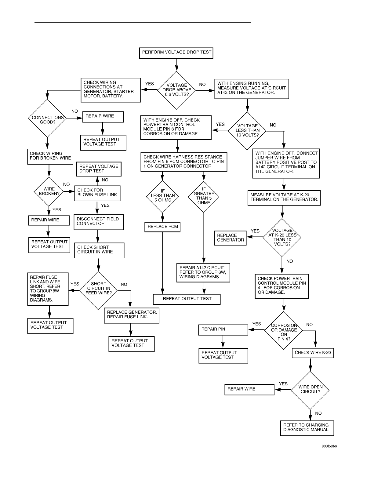
(4) Perform the previous Output Wire Resistance
Test (voltage drop test) (Fig. 5). This will ensure
clean and tight generator/battery electrical connections.
(5) Be sure the generator drive belt is properly
tensioned. Refer to Group 7, Cooling System for
information.
(6) A volt/amp tester equipped with both a battery
load control (carbon pile rheostat) and an inductivetype pickup clamp (ammeter probe) will be used for
this test. Refer to operating instructions supplied
with tester. When using a tester equipped with an
inductive-type clamp, removal of wiring at the generator will not be necessary.
(7) Start the engine and allow it to reach operating
temperature.
(8) Shut engine off.
(9) Turn off all electrical accessories and all vehicle
lighting.
(10) Connect the volt/amp tester leads to the battery. Be sure the carbon pile rheostat control is in the
OPEN or OFF position before connecting leads. See
Load Test in Group 8A, Battery for more information.
Also refer to the operating instructions supplied with
test equipment.
(11) Connect the inductive clamp (ammeter probe).
Refer to the operating instructions supplied with test
equipment.
(12) If volt/amp tester is not equipped with an
engine tachometer, connect a separate tachometer to
the engine.
TEST
(1) Perform the previous test Preparation.
(2) Fully engage the parking brake.
(3) Start engine.
(4) Bring engine speed to 2500 rpm.
(5) With engine speed held at 2500 rpm, slowly
adjust the rheostat control (load) on the tester to
obtain the highest amperage reading. Do not allow
voltage to drop below 12 volts. Record the reading.
This load test must be performed within 15 seconds to prevent damage to test equipment. On
certain brands of test equipment, this load will be
applied automatically. Refer to the operating manual
supplied with test equipment.
(6) The ammeter reading must meet the Minimum
Test Amps specifications as displayed in the Generator Ratings chart. This can be found in the Specifications section at the end of this group. A label stating
a part reference number is attached to the generator
case. On some engines this label may be located on
the bottom of the case. Compare this reference number to the Generator Ratings chart.
(7) Rotate the load control to the OFF position.
(8) Continue holding engine speed at 2500. If EVR
circuitry is OK, amperage should drop below 15–20
amps. With all electrical accessories and vehicle
lighting off, this could take several minutes of engine
operation. If amperage did not drop, refer to the
appropriate Powertrain Diagnostic Procedures manual for testing.
(9) Remove volt/amp tester.
If minimum amperage could not be met, refer to
the appropriate Powertrain Diagnostic Procedures
manual for testing.
Page 9
NO
PERFORM VOLTAGE DROPTESTCHECK WIRING CONNEC-TIONS AT GENERATOR,STARTER, MOTOR, BAT-TERY. YES VOLTAGEDROPABOVE0.6VOLTS?
CHECK WIRE HARNESS RESISTANCE FROM PIN6 PCM CONNECTOR TO PIN 1 ON GENERATORCONNECTOR
REPAIR A142 CIRCUIT.REFER TO GROUP 8W, WIR-ING DIAGRAMS CHECKPOWERTRAINCONTROLMODULEPIN41FORCORROSIONORDAMAGE.
REPEAT OUTPUT TESTREPEAT OUTPUT VOLT-AGE TEST REPLACE GENERATORREPAIR FUSE LINK.REPEAT OUTPUT VOLT-AGE TEST REPAIR PIN YES CORROSIONORDAMAGEONPIN4?NOREPEAT OUTPUT VOLT-AGE TEST CHECK WIREK-20REPAIR WIRE YES WIRE OPENCIRCUIT?NOREFER TO CHARGING DIAG-NOSTIC MANUAL
NO
WITH ENGINE RUNNING,MEASURE VOLTAGE AT CIR-CUIT A142 ON THE GENERA-TOR.CONNEC-TIONS GOOD? NO REPAIR WIRE. WITH ENGINE OFF, CHECK POWER-TRAIN CONTROL MODULE PIN 6FOR CORROSION OR DAMAGE YES VOLTAGELESSTHAN10VOLTS?NOREPEAT OUTPUT VOLT-AGE TEST CHECK WIRING FORBROKEN WIREREPEAT VOLTAGEDROP TEST
WITH ENGINE OFF, CONNECTJUMPER WIRE FROM BATTERYPOSITIVE POST TO A142 CIR-CUIT TERMINAL ON THE GEN-ERATOR.WIREBROKEN? NO CHECKFORBLOWNFUSELINK NO IF LESSTHAN 5OHMS IFGREATERTHAN 5OHMS MEASURE VOLTAGE AT K-20 TERMI-NAL ON THE GENERATOR.YES YESREPAIR WIRE DISCONNECT FIELDCONNECTOR REPLACE PCM REPLACEGENERATOR YES VOLTAGE ATK-20 LESSTHAN 10VOLTS?REPEAT OUTPUTVOLTAGE TEST CHECK SHORT CIRCUITIN WIREREPAIR FUSE LINKAND WIRE SHORT.REFER TO GROUP8W WIRING DIA-GRAMS. YES SHORTCIRCUITINFEEDWIRE?
NO
PL CHARGING SYSTEM 8C - 9
DIAGNOSIS AND TESTING (Continued)
Fig. 5 Voltage Drop Test
Page 10
BATTERY TRAYBATTERY TEMPERATURESENSORSENSOR HARNESSENGINE WIRING HARNESS
8C - 10 CHARGING SYSTEM PL
DIAGNOSIS AND TESTING (Continued)
BATTERY TEMPERATURE SENSOR
To perform a complete test of this sensor and its
circuitry, refer to the appropriate Powertrain Diagnostic Procedures manual. To test the sensor only,
refer to the following:
(1) The sensor is located under the battery and is
attached to the battery tray (Fig. 6). A two-wire pigtail harness is attached directly to the sensor. The
opposite end of this harness connects the sensor to
the engine wiring harness.
Fig. 6 Battery Temperature Sensor
(2) Disconnect the two-wire pigtail harness from
the engine harness.
(3) Attach ohmmeter leads to the wire terminals of
the pigtail harness.
(4) At room temperature of 25° C (75–80° F), an
ohmmeter reading of 9,000 (9K) to 11,000 (11K) ohms
should be observed.
(5) If reading is above or below the specification,
replace the sensor.
(6) Refer to the Removal and Installation section
for procedures.
ON-BOARD DIAGNOSTIC SYSTEM TEST
GENERAL INFORMATION
The Powertrain Control Module (PCM) monitors
critical input and output circuits of the charging system, making sure they are operational. A Diagnostic
Trouble Code (DTC) is assigned to each input and
output circuit monitored by the OBD system. Some
circuits are checked continuously and some are
checked only under certain conditions.
If the OBD system senses that a monitored circuit
is bad, it will put a DTC into electronic memory. The
DTC will stay in electronic memory as long as the
circuit continues to be bad. The PCM is programmed
to clear the memory after 50 engine starts if the
problem does not occur again.
DIAGNOSTIC TROUBLE CODES
Diagnostic Trouble Codes (DTC) are two-digit numbers flashed on the malfunction indicator (Check
Engine) lamp that identify which circuit is bad. Refer
to Group 25, On Board Diagnostic for more information. A DTC description can also be read using the
DRB scan tool. Refer to the appropriate Powertrain
Diagnostic Procedures manual for information.
A DTC does not identify which component in a circuit is bad. Thus, a DTC should be treated as a
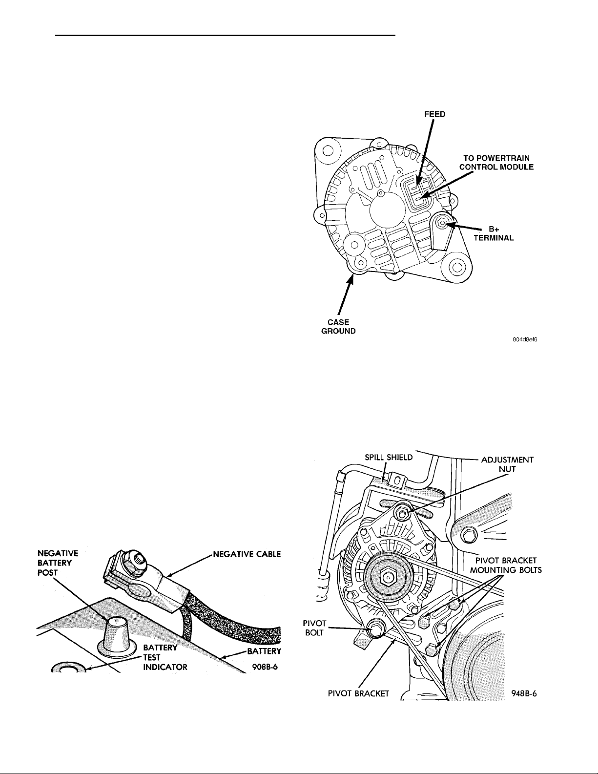
Fig. 7 Generator Diagnostic Trouble Code
Page 11
PL CHARGING SYSTEM 8C - 11
DIAGNOSIS AND TESTING (Continued)
symptom, not as the cause for the problem. In some
cases, because of the design of the diagnostic test
procedure, a DTC can be the reason for another DTC
to be set. Therefore, it is important that the test procedures be followed in sequence, to understand what
caused a DTC to be set.
See the Generator Diagnostic Trouble Code chart
(Fig. 7) for DTC’s which apply to the charging system. Refer to the Powertrain Diagnostic Procedures
manual to diagnose an on-board diagnostic system
trouble code.
RETRIEVING DIAGNOSTIC TROUBLE CODES
To start this function, cycle the ignition switch ONOFF-ON-OFF-ON within 5 seconds. This will cause
any DTC stored in the PCM memory to be displayed.
The malfunction indicator (Check Engine) lamp will
display a DTC by flashing on and off. There is a
short pause between flashes and a longer pause
between digits. All DTC’s displayed are two-digit
numbers, with a four-second pause between codes.
An example of a DTC is as follows:
(1) Lamp on for 2 seconds, then turns off.
(2) Lamp flashes 4 times pauses and then flashes
1 time.
(3) Lamp pauses for 4 seconds, flashes 4 times,
pauses, then flashes 7 times.
(4) The two DTC’s are 41 and 47. Any number of
DTC’s can be displayed, as long as they are in memory. The lamp will flash until all stored DTC’s are
displayed, then it will flash a DTC 55 to indicate the
test is complete.
(3) Raise vehicle with front wheels turned fully to
the right.
Fig. 9 Wire Terminal Connection
(4) Remove the plastic lower splash shield.
(5) Disconnect the generator field circuit wiring
connector (Fig. 11). Squeeze locking tab to release.
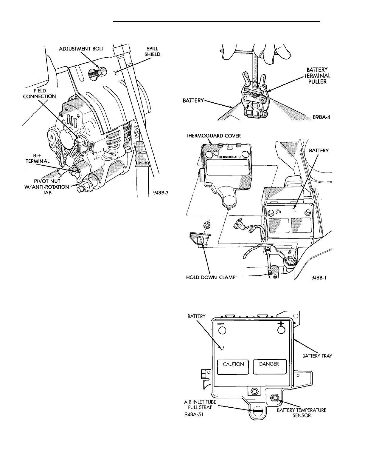
(6) Remove the B+ terminal nut and wire.
(7) Loosen pivot bolt, but do not remove (Fig. 10)
and (Fig. 11).
SPILL SHIELD ADJUSTMENT NUTPIVOT BRACKETMOUNTING BOLTSPIVOT BRACKETPIVOTBOLT
ERASING DIAGNOSTIC TROUBLE CODES
The DRB Scan Tool must be used to erase a DTC.
REMOVAL AND INSTALLATION
GENERATOR
REMOVAL
(1) Disconnect battery negative cable (Fig. 8).
Fig. 8 Removal/Installation of Battery Cables
(2) Loosen but DO NOT remove the generator
adjustment nut.
Fig. 10 Generator Front View
Page 12
ADJUSTMENT BOLT SPILL SHIELDPIVOT NUT W/ANTI-ROTATION TABB+ TERMINALFIELD CONNECTION
BATTERY BATTERYTERMINALPULLER
BATTERY BATTERYTRAYBATTERY TEMPERA-TURE SENSORAIR INLET TUBEPULL STRAP CAUTION DANGER
8C - 12 CHARGING SYSTEM PL
REMOVAL AND INSTALLATION (Continued)
Fig. 12 Removal of Battery Cables
THERMO-GUARDCOVERBATTERYHOLD DOWN CLAMP
Fig. 11 Generator Rear View
(8) Remove the generator drive belt. The generator
spill shield does not need to be removed.
(9) Remove three mounting pivot bracket bolts.
(10) Remove pivot bolt and bracket.
(11) Holding the generator in one hand, remove
adjustment nut and slide the generator off the T-bolt.
The T-bolt does not need to be removed.
(12) Lower the generator and remove through the
wheel well.
INSTALLATION
(1) For installation, reverse above procedures. The
generator field connector has a locking tab and will
snap when fully installed. Refer to group 7 Cooling
System, Belt Removal/Install Adjust. Tighten all fasteners to the proper torque. Refer to the Torque Specifications chart in Group 8A, Battery/Starter/
Charging Systems Diagnostics.
BATTERY TEMPERATURE SENSOR
REMOVAL
(1) Make sure ignition switch is in OFF position
and all accessories are OFF.
(2) Remove battery negative cable first then the
positive cable (Fig. 12).
(3) Remove battery thermoguard (Fig. 13).
Fig. 13 Battery Thermoguard
(4) Remove temperature sensor mounting nut from
battery tray (Fig. 14).
WARNING: TO PROTECT THE HANDS FROM BATTERY ACID, A SUITABLE PAIR OF HEAVY DUTY
RUBBER GLOVES, NOT THE HOUSEHOLD TYPE,
SHOULD BE WORN WHEN REMOVING OR SERVICING A BATTERY. SAFETY GLASSES ALSO SHOULD
BE WORN.
Fig. 14 Battery Temperature Sensor Location
Page 13
BATTERY TRAYBATTERY TEMPERATURESENSORAIR INLETTUBE
PL CHARGING SYSTEM 8C - 13
REMOVAL AND INSTALLATION (Continued)
(5) Disconnect sensor wire connector (Fig. 15).
INSTALLATION
For installation reverse above procedures.
Fig. 15 Battery Temperature Sensor Connector
SPECIFICATIONS
GENERATOR RATINGS
TYPE PART NUMBER RATED SAE AMPS ENGINES MINIMUM TEST AMPS
MELCO 4793190 83 AMPS 2.0L SOHC/DOHC 75 AMPS
TORQUE SPECIFICATIONS
DESCRIPTION TORQUE
Battery Terminal Nut .........9N·m(75in.lbs.)
Battery Hold Down Clamp Bolt . . 9 N·m (75 in. lbs.)
Generator Mounting Bolt ......54N·m(40ft.lbs.)
Generator Pivot Bolt ..........54N·m(40ft.lbs.)
Page 14

 Loading...