

Page 1
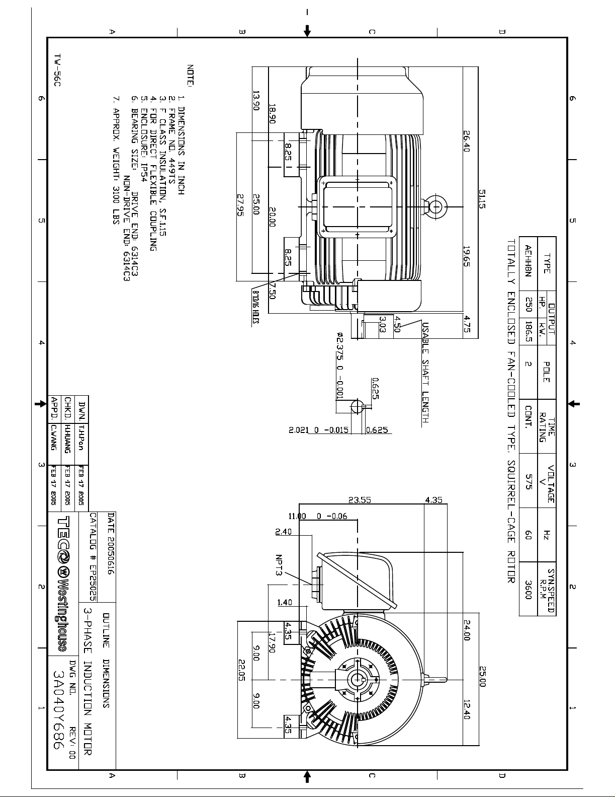
Page 2
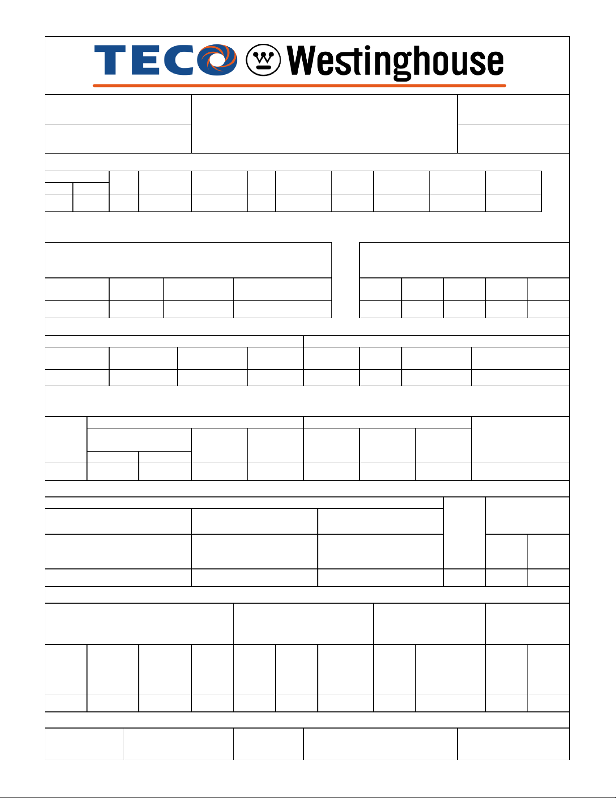
NAMEPLATE INFORMATION
VARIABLE FREQUENCY DRIVE SERVICE
TYPICAL PERFORMANCE
210
AEHH8N
HZ
6~60
CONSTANT TORQUE
FRAME
SIZE
449TS
PERFORMANCE DATA
3-PHASE INDUCTION MOTOR
ENCLOSURE
CATALOG#
TEFC
EP25025
MAX
ALLOWABLE
WK
2
(lb-ft2)
INERTIA
ISSUED
TYPE
250
186.5
POLE
2
OUTPUT
HP
KW
1/12/2017
40oC
INS.
CLASS
F
RATED
AMBIENT
VOLTAGE
575
HZ
60
250
3600
366
B
TIME
RATING
CONT.
SERVICE
FACTOR
1.15
NEMA
DESIGN
HP
25~250
60
366
TORQUE
(lb-ft)
0.913~366
RPM
360~3600
3583
MIN.%
NOM.%
FULL LOAD
HZ
3~60
RPM
180~3600
0.0313~250
HP
1/2 LOAD
%
POWER FACTOR
3/4 LOAD
%
1/2 LOAD
%
EFFICIENCY
FULL
LOAD
RPM
SOUND
PRESSURE
LEVEL @ 3 FT
Db(A)
95
95.8
95.4
94.5
88
85.5
82
FULL LOAD
%
3/4 LOAD
%
TORQUE
ROTOR
WR
2
(lb-ft2)
NEMA
LOAD
WK
2
(lb-ft2)
NO LOAD
FULL LOAD
AT
575
VOLT
366.00
103
83
210
LOCKED ROTOR
CURRENTS
FULL
LOAD
(lb-ft)
LOCKED
ROTOR
%FLT
PULL
UP
%FLT
BREAK
DOWN
%FLT
44
210
10.2
R1R2X1
0.0155
0.014
0.149
0.3
5.18
HOT
G
1
ALLOWABLE
STARTS
PER HOUR
2
NEMA
LOAD
WK
2
Sec
MAX
ALLOWABLE
WK
2
Sec
ACCEL TIME (DOL)
25
17
COLD
COLD
HOT
APPROVED:
M. PRATER
DRAWING NO.
31057EP2502
8.50
OHMS/PHASE EQUIVALENT WYE CIRCUIT
(AT RATED OPERATING TEMPERATURE 25
o
C)
X2
X
m
TORQUE
(lb-ft)
TORQUE
(lb-ft)
0
REVISION:
83
NEMA
KVA
CODE
LETTER
SAFE STALL
TIME IN
SECONDS
1460
AT
575
VOLT
222.1
AT
575
VOLT
37.4
VARIABLE TORQUE
HZHPRPM
CONSTANT HORSEPOWER
Page 3
DATE:
CATALOG NO.:
June 8, 2009 EP250245
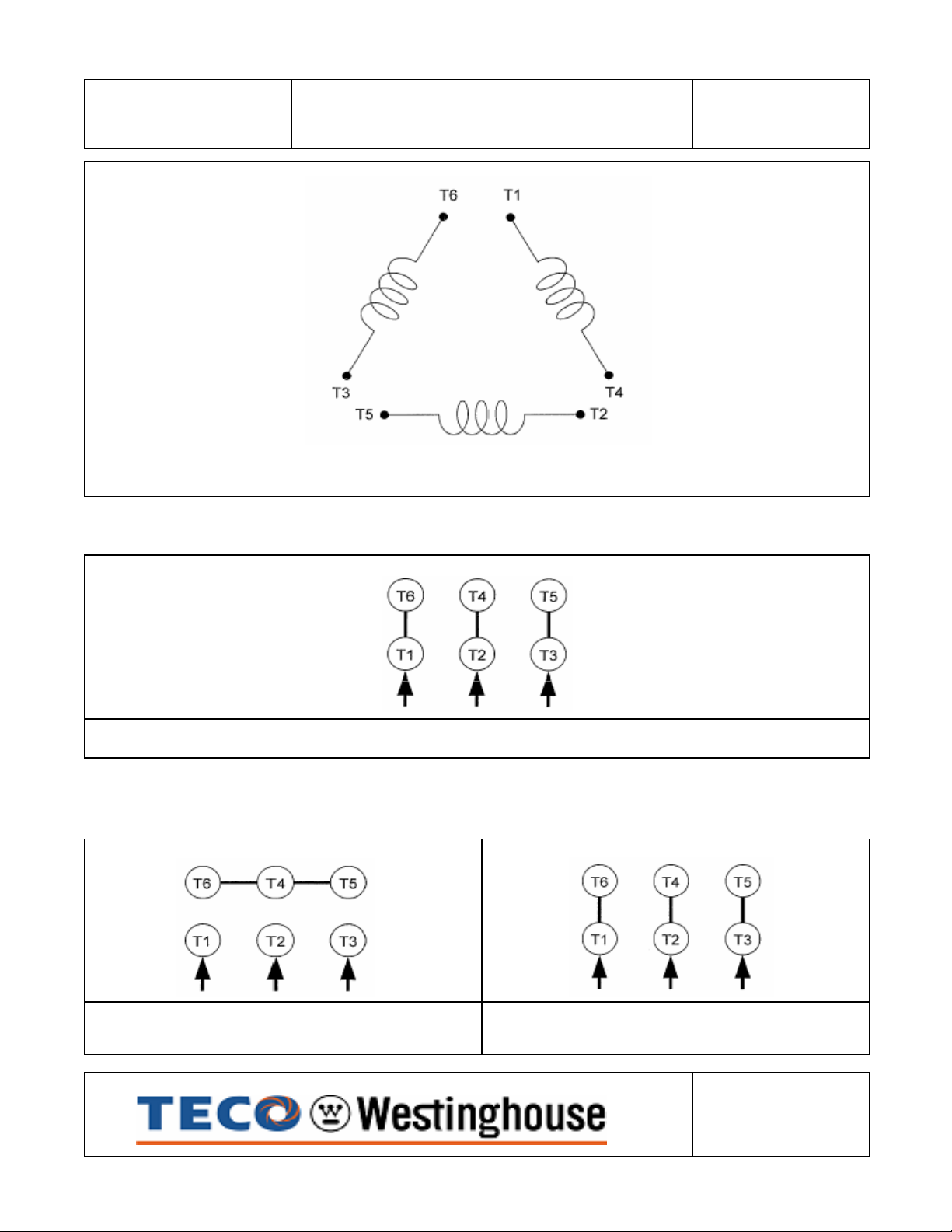
CONNECTION DIAGRAM
SCHEMATIC - ∆ / Y CONNECTION
ACROSS THE LINE CONNECTION
575 VOLT CONNECTION
WYE START-DELTA RUN CONNECTION
LINE LINE
575 VOLT START 575 VOLT RUN
DWG NO.
DAC-1545-3A
Page 4
INSTALLATION AND
MAINTENANCE INSTRUCTIONS
FOR THREE PHASE
INDUCTION MOTORS
Frames 143T - 449TZ
Page 5

RECEIVING
1. Check nameplate data.
2. Check whether any damage has occurred during transportation.
3. After removal of shaft clamp, turn shaft by hand to check that it turns freely.
4. If motor is to be reshipped (alone or installed to another piece of equipment)theshaft must again
be clamped to prevent axial movement.
Note: Remove the bearing clamp before turning the shaft on 284T-449TZ frame motors.
WARNING
THE FOLLOWING SAFETY PRECAUTIONS MUST BE OBSERVED:
1. Electric rotating machinery and high voltage can cause serious or fatal injury if improperly
installed, operated or maintained. Responsible personnel should be familiarized with
NEMA MG-1; Safety Standards for Construction and Guide Selection. Installation and Use of
Electric Motors and Generators; National Electric Code and all local safety requirements.
2. Whenservicing,allpower sources to the motor and to the accessorydevicesshouldbe
de-energized and disconnected and all rotating parts should be at standstill.
3. Liftingmeans, when supplied, are intendedfor lifting the motor only. Whentwo lifting
devices are supplied with the motor a dual chain must be used.
4. Suitable protection must be used when working near machinery with high noise levels.
5. Safeguard or protective devices must not be by-passed or rendered inoperative.
6. The frame of this machine must be grounded in accordance with the National Electric Code and
applicable local codes.
7. A suitable enclosure should be provided to prevent accessto the motor by other than
authorized personnel. Extra caution should be observed around motors that are
automatically or have automatic re-setting relays as they may restart unexpectedly.
8. Shaft key must be fully captive or removed before motor is started.
9. Provide propersafeguards for personnel against possible failure of motor-mounted brake,
particularly on applications involving overhauling loads.
10.Explosion proof motors are constructed to comply with the label service procedure manual, repair
of these motors must be made by TECO-Westinghouse Motor Company or U/L listed service
center in order to maintain U/L listing.
LOCATION
1. Drip-proof motors are intended for usewhere atmosphere is relativelyclean, dry, well
ventilated and non-corrosive.
2. Totally enclosedmotors maybeinstalled wheredirt, moisture, or dust are present andin outdoor
locations.
3. Explosion-proof motors are built for use in hazardous locations as indicated by
Underwriters’ label on the motor.
4. Chemicalduty enclosed motors are designedforinstallation in high corrosionorexcessive
moisture locations.
Note: in all cases, no surrounding structure should obstruct normal flow or
ventilating air through or over the motor.
Page 6
MOUNTING
2/82537
1/26090
5/8
120
180
1. Mount motor securely on a firm, flat base. All ball bearing normal thrust motors up to and
including 256T frame size may be side-wall or ceiling mounted; all others check nearest
TECO-Westinghouse office for mounting recommendations.
2. Align motor accurately, using a flexible coupling if possible. For drive recommendations,
consult with drive or equipment manufacturer, or TECO-Westinghouse.
3. Mounting bolts must be carefullytightened to prevent changes in alignment and possible
damageto the equipment. The recommended tightening torque’s for medium carbon steel bolts,
identified by three radial lines at 120 degrees on the head, are:
Bolt Size
Recommended Torque (Ft-lb.)
Minimum Maximum
3/4 210 320
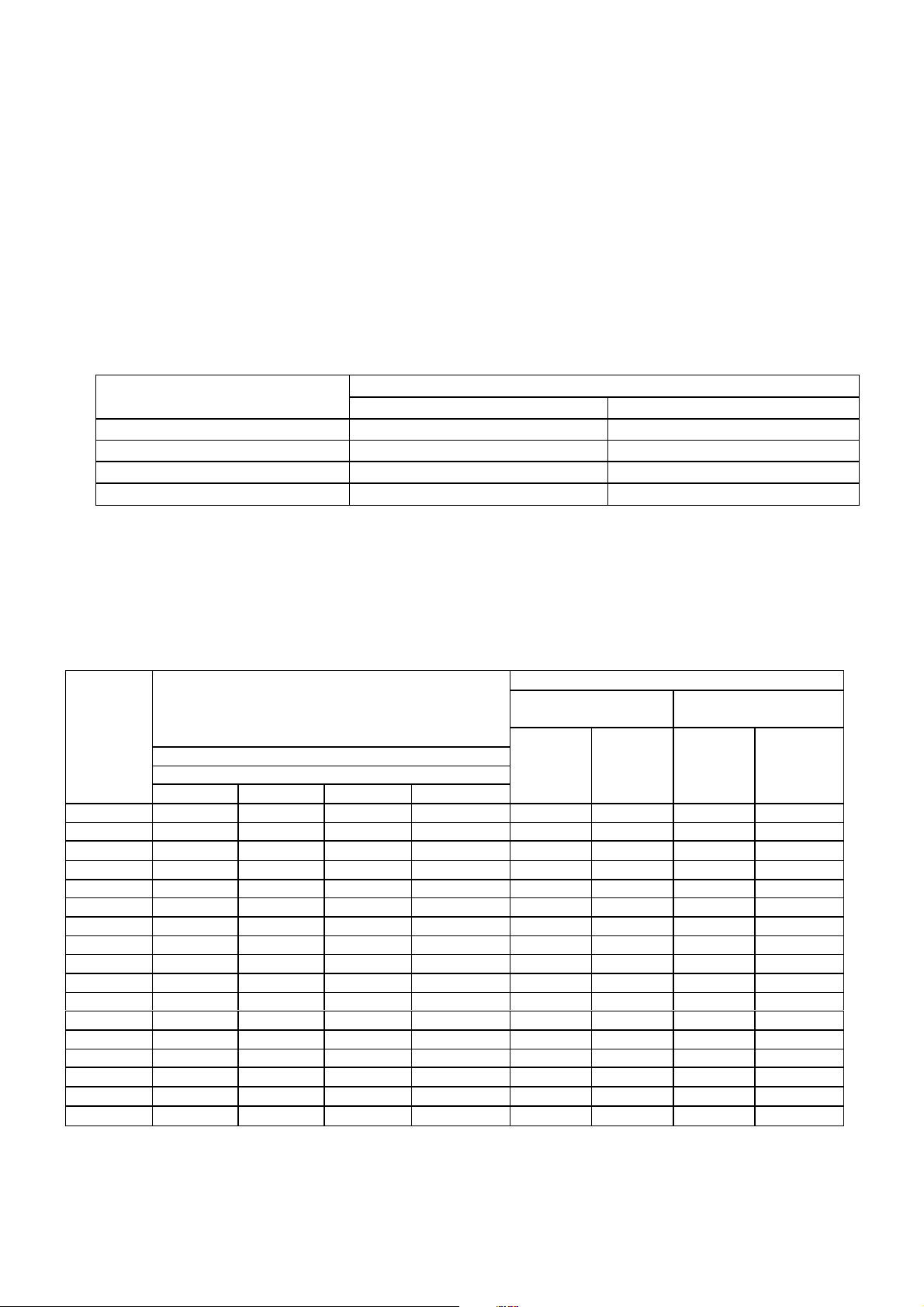
4. V-belts Sheave PitchDiametersshould not be lessthan thoseshown in Table1 (NEMA
recommended values)
5. Tighten belts only enough to prevent slippage. Belt speed should not exceed 5000 ft. per
min.
TABLE 1. V-Belt Sheave Pitch Diameters (MG1-14.42)
V-Belt Sheave
Conventional
A, B, C, D AND E
Minimum
Horsepower at
Frame
Number 3600 1800 1200 900
143T 1.5 1 .75 .5 2.2 4.25 2.2 2.25
145T 2-3 1.5-2 1 .75 2.4 4.25 2.4 2.25
182T 3 3 1.5 1 2.4 5.25 2.4 2.75
182T 5 ... ... ... 2.6 5.25 2.4 2.75
184T ... ... 2 1.5 2.4 5.25 2.4 2.75
184T 5 ... ... ... 2.6 5.25 2.4 2.75
184T 7.5 5 ... ... 3.0 5.25 3.0 2.75
213T 7.5-10 7.5 3 2 3.0 6.5 3.0 3.375
215T 10 ... 5 3 3.0 6.5 3.0 3.375
215T 15 10 ... ... 3.8 6.5 3.8 3.375
254T 15 ... 7.5 5 3.8 7.75 3.8 4
254T 20 15 ... ... 4.4 7.75 4.4 4
256T 20-25 ... 10 7.5 4.4 7.75 4.4 4
256T ... 20 ... ... 4.6 7.75 4.4 4
284T ... ... 15 10 4.6 9 4.4 4.625
284T ... 25 ... ... 5.0 9 4.4 4.625
286T ... 30 20 15 5.4 9 5.2 4.625
Synchronous Speed, RPM
Pitch
Diameter
Inches
*Maximum
Width
Inches
Minimum
Outside
Diameter
Inches
Narrow
3V, 5V, AND 8V
**Maximum
Width
Inches
Page 7
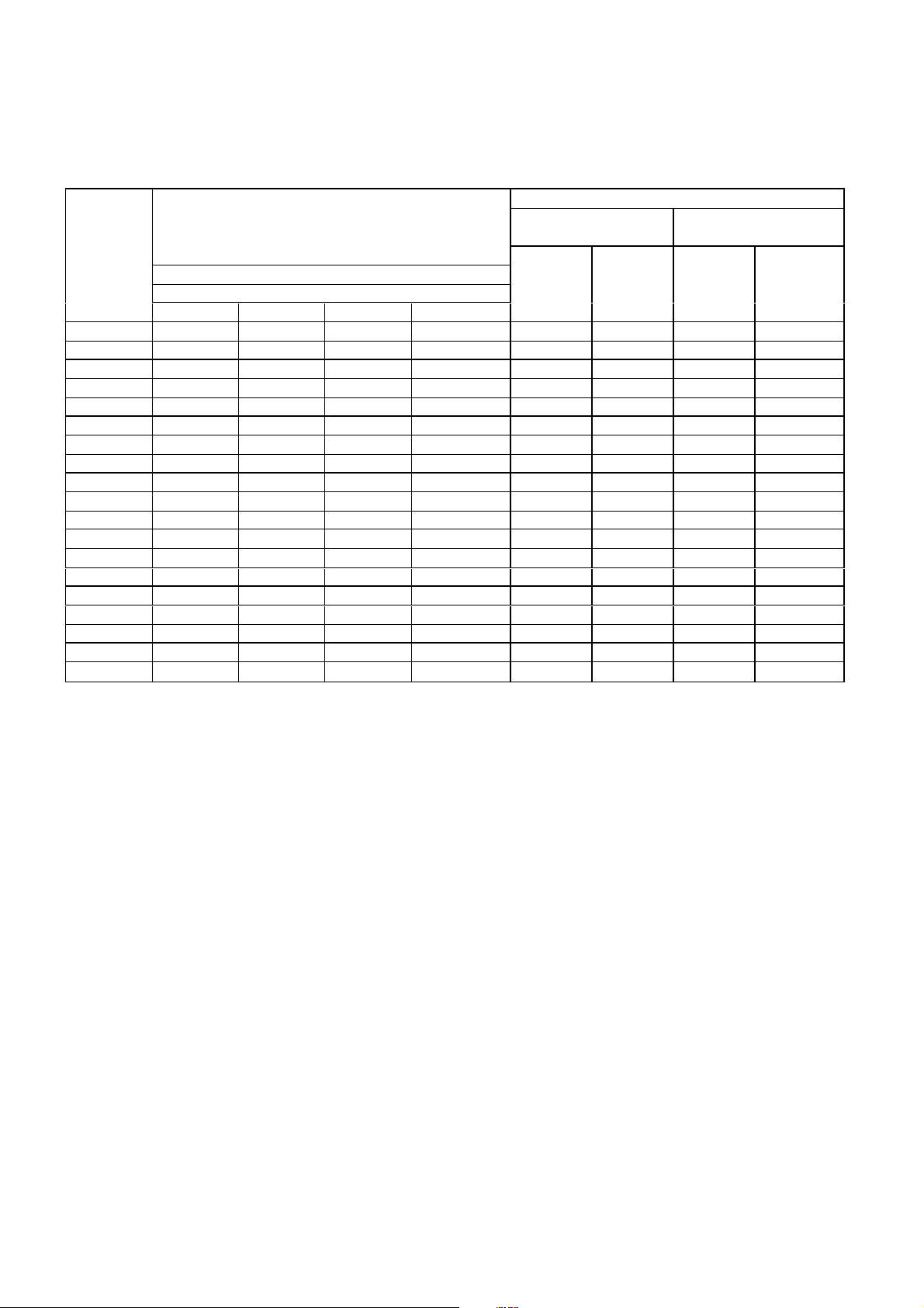
TABLE 1. V-Belt Sheave Pitch Diameters (MG1-14.42)
V-Belt Sheave
Conventional
A, B, C, D AND E
Minimum
Horsepower at
Frame
Number 3600 1800 1200 900
324T ... 40 25 20 6.0 10.25 6.0 5.25
326T ... 50 30 25 6.8 10.25 6.8 5.25
364T ... ... 40 30 6.8 11.5 6.8 5
364T ... 60 ... ... 7.4 11.5 7.4 5.785
365T ... ... 50 40 8.2 11.5 8.2 5.785
365T ... 75 ... ... 9.0 11.5 8.6 5.785
404T ... ... 60 ... 9.0 14.25 8.0 7.25
404T ... ... ... 50 9.0 14.25 8.4 7.25
404T ... 100 ... ... 10.0 14.25 8.6 7.25
405T ... ... 75 60 10.0 14.25 10.0 7.25
405T ... 100 ... ... 10.0 14.25 8.6 7.25
405T ... 125 ... ... 11.5 14.25 10.5 7.25
444T ... ... 100 ... 11.0 16.75 10.0 8.5
444T ... ... ... 75 10.5 16.75 9.5 8.5
444T ... 125 ... ... 11.0 16.75 9.5 8.5
444T ... 150 ... ... ... 16.75 10.5 8.5
445T ... ... 125 ... 12.5 16.75 12.0 8.5
445T ... ... ... 100 12.5 16.75 12.0 8.5
445T ... 150 ... ... ... 16.75 10.5 8.5
Synchronous Speed, RPM
Pitch
Diameter
Inches
*Maximum
Width
Inches
Minimum
Outside
Diameter
Inches
Narrow
3V, 5V, AND 8V
**Maximum
*Max. Sheave width = 2(N-W) - .25
**Max Sheave width = N-W
***Sheave ratios grater than 5:1 and center-to-center distance less than the diameter of the
large sheave should be referred to TECO-Westinghouse.
Width
Inches
POWER SUPPLY & CONNECTIONS
1. Wiring of motor and control, overload protection and grounding should be in accordance with
National Electrical Code and all local safety requirements.
2. Nameplate voltage and frequency should agree with power supply. Motor will operate
satisfactorily on line voltage within ±10% of nameplate voltage; or frequency with ±5% and
with a combined variation not to exceed ±10%. 230-volt motors can be used on 208-volt
networksystems, but with slightly modifiedperformance characteristics as shown on the
nameplate.
3. Dual voltage and single voltage motors can be connected for the desired voltage by
following connection diagram shown on the nameplate or inside of the conduit box.
4. All Explosion Proofmotors have Temperature Limiting Devices in the motor enclosureto
preventexcessive external surface temperatureof the motor in accordance with U/L
standards. Terminals of thermal protectors (P1 & P2) should be connected to the motor
control equipment, according to the connection diagram inside of the conduit box.
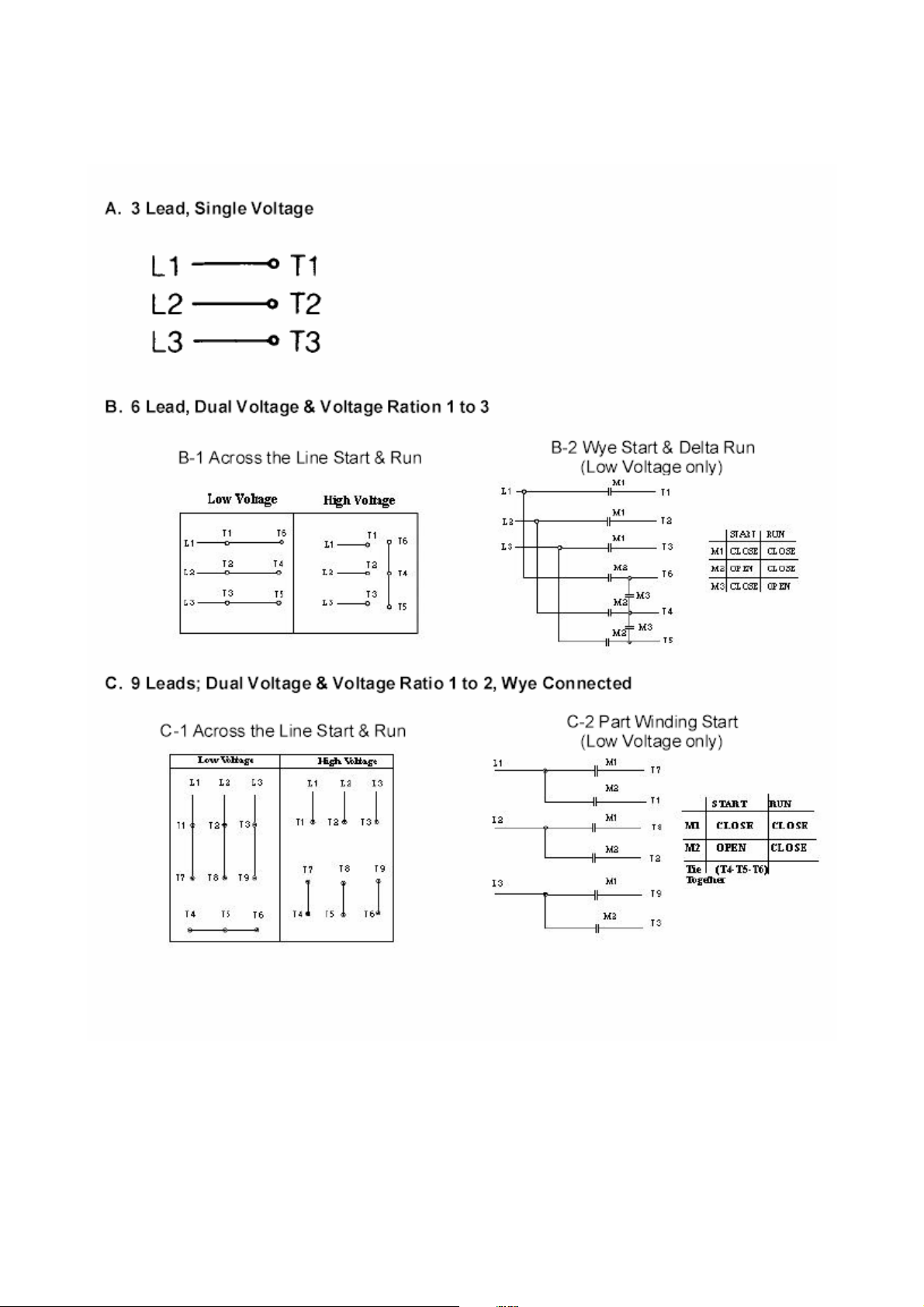
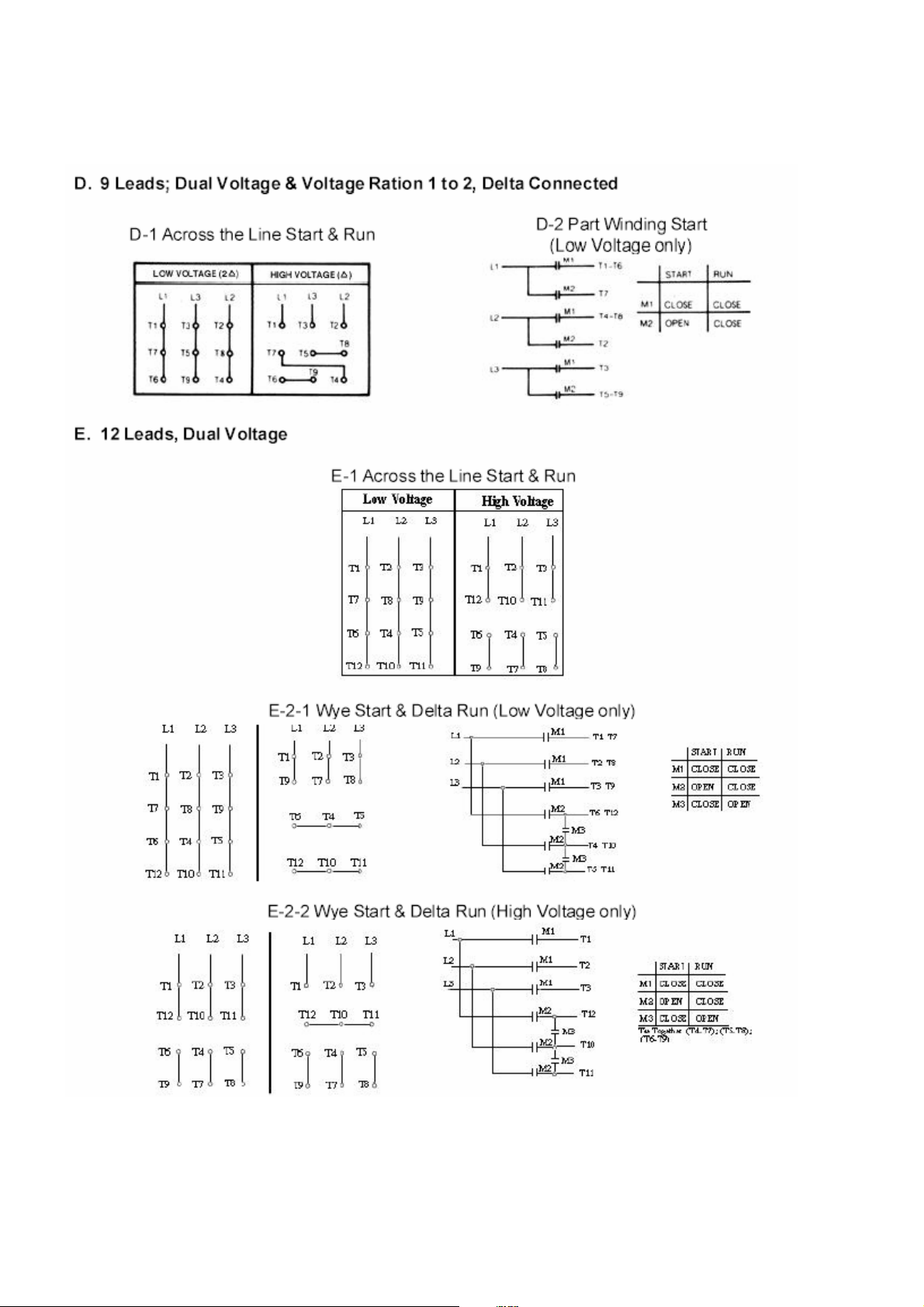
5. Standard connection diagram for three phase, not thermally protected, dual rotation motors
are shown in diagrams A through E. (Note: To change rotation, Interchange any two line
leads)
Page 8
Page 9
Page 10
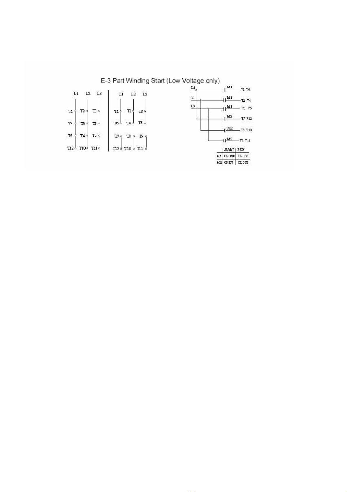
*Important: For Part Winding Start, M2 contactor should be closed within two (2) seconds
after M1 contactor is closed.
Only 4 pole and above (e.g., 6P, 8P...) motors are satisfactory for PartWinding Start
at low voltage.
START UP
1. Disconnect load and start motor. Check direction of rotation. If rotation must be changed,
ALLOW THE MOTOR TO STOP COMPLETLEY. Interchange any two leads of a three-phase
motor.
2. Connect load. The motor should start quickly and run smoothly. If no, shut power off at once.
Recheck the assembly including all connections before restarting.
3. If excessive vibration is noted, checkforloose mountingbolts too flexiblemotor support
structure or transmitted vibration from adjacent machinery. Periodic vibration checks should
be made; foundations often settle.
4. Operate under load for short period of time and check operating current against nameplate.
TESTING
If the motor has beenin storagefor an extensive period or has been subjectedtoadverse moisture
conditions, it is bestto check the insulation resistanceofthestatorwindingwith a megometer.
Depending on the length and conditions of storage it may be necessaryto regrease or change
rusted bearings.
If the resistance is lower than one megohm the windings should be driedin one of the following two
ways:
1. Bakeinoven at temperatures not exceeding194°F until insulationresistancebecomes
constant.
2. With rotor locked, apply low voltage and gradually increase the current through windings until
temperature measured with a thermometer reaches 194°F. Do not exceed this temperature.
Page 11

MAINTENANCE
1 Thru 30 Hp, 1800 rpm and below
7 years
3 years
180 days
1 Thru 20 Hp, 3600 rpm
5 years
2 years
90 days
INSPECTION
Inspect motor at regular intervals. Keep motor clean and ventilation openings clear.
LUBRICATION
1. Frame 143T-256T: Double shieldedandpre-lubricated ball-bearing motors without grease
fittings and don’t need re-lubrication, except on MAX-E1®and MAX-E2®products which
have re-greasable features.
2. Frames 280TS, 320-449TZ(TS): Motors having grease fittings and grease discharge
devices at brackets. Motors are shipped with grease for initial running. It is necessary to
re-lubricate anti-friction bearing motors periodically, depending on size and type of service. See
Table 2 to provide maximum bearing life. Excessive or too frequent lubrication may damage
the motor.
TABLE 2
Horsepower
40 Thru 75 Hp, 1800 rpm and below 210 days 70 days 30 days
100 Thru 150 Hp, 1800 rpm and below 90 days 30 days 15 days
25 Thru 75 Hp, 3600 rpm 180 days 60 days 30 days
100 Thru 150 Hp, 3600 rpm 90 days 30 days 15 days
Note:
A. Standard conditions: 8 hours operation per day, normal or light loading, clear and 40°C
ambient conditions.
B. Severe conditions: 24-hour operation per day or light shock loading, vibration or in dirty or
dusty conditions.
C. Extreme conditions: With heavy shock loading or vibration or dusty conditions.
D. For double shielded bearings, above data(lubrication frequency)means thatthe
bearing must be replaced.
3. Be sure fittings are clean and free from dirt. Using a low-pressure grease gun, pump in the
recommended grease until new grease appears at grease discharge hole.
4. Use the POLYUREA grease unless special grease is specified on the nameplate.
5. If re-lubrication is to be performed with the motor running, stay clear of rotating parts. After
re-greasing, allow the motor to run for ten to thirty minutes.
Standard
Conditions
Severe
Conditions
Extreme
Conditions
Page 12

RENEWAL PARTS
1. Use onlygenuine TECO-Westinghouse renewal partsor as recommendedbyTECOWestinghouse Motor Company.
2. When youorder renewal parts please specifycomplete information to TECO-Westinghouse
office/agent such as type, frame no., poles, horsepower, voltage, series no., quantity, etc.
FOR FURTHER INFORMATION PLEASE CONTACT
TECO-WESTINGHOUSE MOTOR COMPANY
Round Rock, TX
 Loading...