

Page 1
ELM303
1234876
5
Camcorder Time–Lapse Control
Description
542
3
6
7
Features
The ELM303 is a specialized circuit for creating
time-lapse videos on suitably equipped camcorders.
The camcorder to be controlled must have a Control
L (LANC) port, and also be capable of responding to
power control signals. This is usually only available
with the mini DIN connectors, and not the 2.5mm
stereo plug interfaces.
The ELM303 provides intervals of 10 minutes to
24 hours between recordings, without requiring any
external timing components. Recording durations of
either 1 second or 10 seconds is also selectable.
One additional feature allows manually triggered
recordings to be initiated when all three interval
inputs are at a low level. Recording will begin
immediately and will continue as long as the inputs
remain low. This combination is fully debounced,
simplifying the interface to mechanical switches.
The ELM303 has been ‘hard–coded’ to send the
Control L hex command ‘33’ (word 1) to device ‘18’
(word 0), and cannot be modified. Be sure to verify
that these are appropriate for your camera before
committing to any designs.
Applications
• Delays of 10 minutes to 24 hours with no external
timing components
• Recording durations of 1 or 10 seconds
• Low power CMOS design - typically 1mA at 5V
• Security feature allows on demand recording
• Initial recording after 1 minute to verify system
operation and connections
• Pulsed power output to control camera power
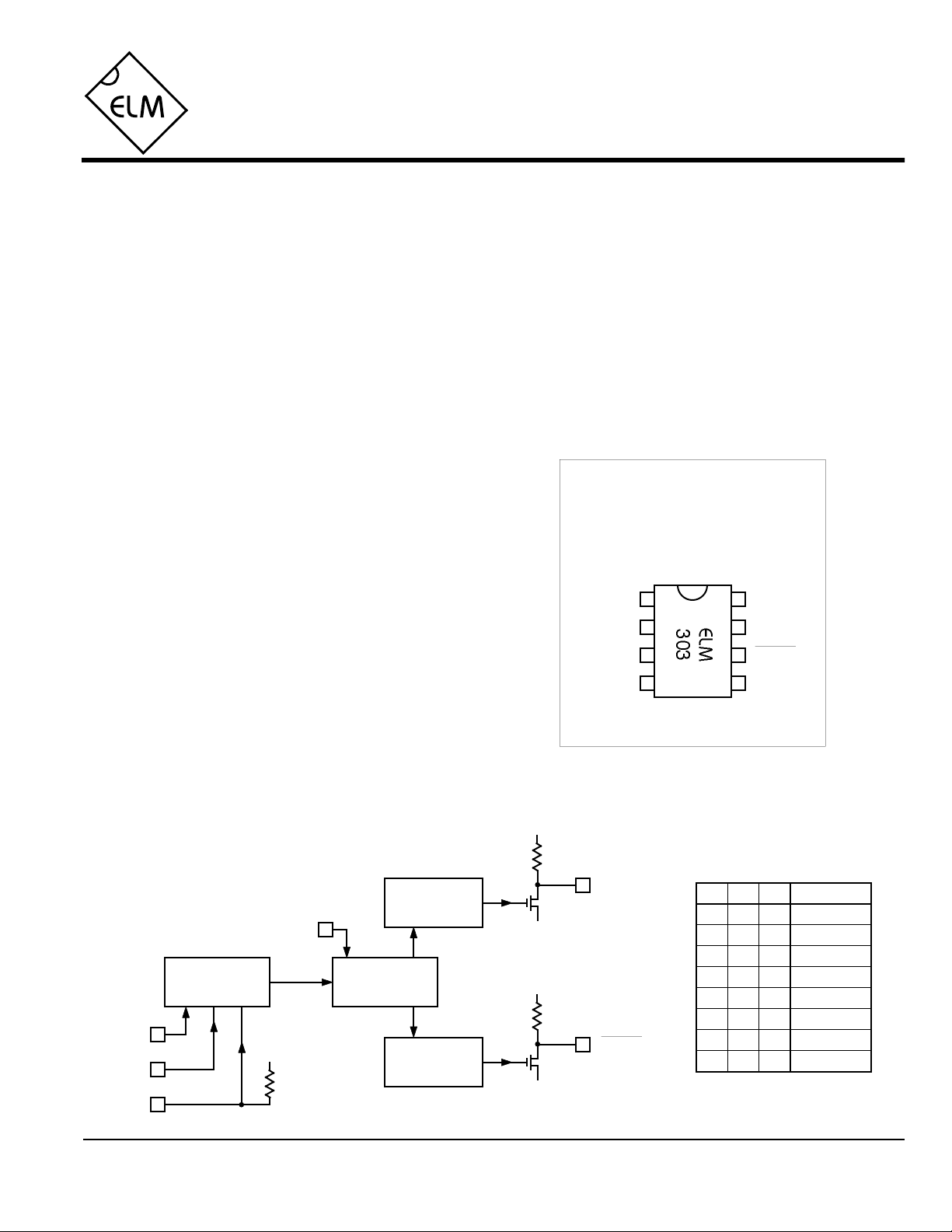
Connection Diagram
PDIP and SOIC
(top view)
VDD VSS
I2
I1
LANC
Power
D0I0
• Time-lapse video recording
• Security monitoring
• Long period time delay circuits
Block Diagram
Programmable
Delay
I2
VDD
I1
I0
ELM303DSA
VDD
Control L
Driver
D0
Control
200ms Pulse
Generator
VSS
VDD
VSS
Elm Electronics – Circuits for the Hobbyist
< http://www.elmelectronics.com/ >
LANC
Power
I2 I1 I0 Interval
L L L continuous
L L H 10 min
L H L 30 min
L H H 60 min
H L L 3 hrs
H L H 6 hrs
H H L 12 hrs
H H H 24 hrs
Table 1
1 of 5
Page 2

ELM303
Pin Descriptions
Stresses beyond those listed here will likely damage
the device. These values are given as a design
guideline only. The ability to operate to these levels
is neither inferred nor recommended.
VDD (pin 1)
This pin is the positive supply pin, and should
always be the most positive point in the circuit.
Internal circuitry connected to this pin is used to
provide power on reset of the microprocessor, so
an external reset signal is not required. Refer to
the Electrical Characteristics section for further
information.
I2 (pin 2), I1 (pin 3) and I0 (pin 4)
The time interval between each recording is
determined by the logic levels at these pins, as
shown in Table 1. The I0 input on pin 4 has a
high value pullup resistor to simplify wiring in
some instances (see the Example Applications).
level results in a nominal time of 10 seconds,
and a low level provides 1 second.
Power (pin 6)
This is an open drain output that is driven low at
the beginning and end of each recording cycle in
order to toggle the camcorder power on and off.
This output is generally connected to pin 3 of the
mini DIN Control L connector. An internal pullup
resistor is provided for a nominal drain load.
LANC (pin 7)
This is the open drain Control L (LANC) interface
pin. An internal pullup resistor is provided for a
nominal drain load.
D0 (pin 5)
This input is used to select the recording duration
(time between start and stop commands). A high
VSS (pin 8)
Circuit common is connected to this pin. This is
the most negative point in the circuit.
Ordering Information
These integrated circuits are available in either the 300 mil plastic DIP format, or in the 200 mil SOIC surface
mount type of package. To order, add the appropriate suffix to the part number:
300 mil Plastic DIP............................... ELM303P 200 mil SOIC.....................................ELM303SM
Absolute Maximum Ratings
Storage Temperature.......................-65°C to +150°C
Ambient Temperature with
Power Applied....................................-40°C to +85°C
Voltage on VDD with respect to VSS............0 to +7.5V
Voltage on any other pin with
respect to VSS........................... -0.6V to (VDD + 0.6V)
Note:
All rights reserved. Copyright ©1999 Elm Electronics.
Every effort is made to verify the accuracy of information provided in this document, but no representation or warranty can be
given and no liability assumed by Elm Electronics with respect to the accuracy and/or use of any products or information
described in this document. Elm Electronics will not be responsible for any patent infringements arising from the use of these
products or information, and does not authorize or warrant the use of any Elm Electronics product in life support devices and/or
systems. Elm Electronics reserves the right to make changes to the device(s) described in this document in order to improve
reliability, function, or design.
ELM303DSA
Elm Electronics – Circuits for the Hobbyist
2 of 5
< http://www.elmelectronics.com/ >
Page 3

ELM303
Electrical Characteristics
All values are for operation at 25°C and a 5V supply, unless otherwise noted. For further information, refer to note 1 below.
Characteristic Minimum Typical Maximum ConditionsUnits
Supply voltage, VDD 3.0 5.0 5.5 V
VDD rate of rise 0.05 V/ms
Average supply current, IDD 1.0 2.4 mA
Input low voltage VSS 0.15 VDD V
Input high voltage VDD V0.85 VDD
Internal pullup resistances
(see note 3)
Output low voltage 0.6 V Current (sink) = 8.7mA
Circuit timing 200 msec180 220
Power Pulse
Control L bus
500 KΩ300 600
see note 2
Pin 4 (I0)
Pins 6 (Power) and 7 (LANC)
KΩ3020 50
VDD = 5V (see note 4)
VDD = 5V (see note 4)
baud9600
Notes:
1. This integrated circuit is produced with a Microchip Technology Inc.’s PIC12C5XX as the core embedded
microcontroller. For further device specifications, and possibly clarification of those given, please refer to the
appropriate Microchip documentation.
2. This spec must be met in order to ensure that a correct power on reset occurs. It is quite easily achieved
using most common types of supplies, but may be violated if one uses a slowly varying supply voltage, as
may be obtained through direct connection to solar cells, or some charge pump circuits.
3. The value of the internal pullup resistance is both supply and temperature dependent.
4. Circuit timing is affected by supply and temperature variations as shown in Figure 1 below. Results shown
are average values that can be expected.
ELM303DSA
fast
% Error
slow
-6
-4
-2
0
+2
+4
+6
-40 0 40 80
Temperature (°C)
Figure 1. Average Timing Error
Elm Electronics – Circuits for the Hobbyist
< http://www.elmelectronics.com/ >
VDD = 5V
VDD = 3V
3 of 5
Page 4

Functional Block Diagram
ELM303
The operation of the ELM303 can best be
described through the following block diagram. All
of the main functions are shown, while initialization,
timekeeping, etc. are implied. The power on and off
delays are internally set, and are not adjustable.
Note that on powerup, and after responding to
a ‘000’ interval code, the circuit always initiates a
record cycle after one minute. This allows the
operator to verify that the system is operating
properly.
Pulse Power
for 200msec
wait for timeout
or I=’000’
Save the state
of all pins
no
Control L
bus active
Loop
PowerUp
wait 1 minute
?
send 0x1833 to
the camcorder
wait 5 sec
Pulse Power
for 200msec
no
wait 10 sec
yes
Is
I=’000’
?
send 0x1833 to
the camcorder
if D0=0, wait 1s
else wait 10s
yes
send 0x1833 to
the camcorder
wait 5 sec
yes
Was
I=’000’
?
no
ELM303DSA Elm Electronics – Circuits for the Hobbyist
Go to PowerUp
Pulse Power
for 200msec
Go to Loop
4 of 5
< http://www.elmelectronics.com/ >
Page 5

Example Applications
ELM303
1234876
5
1234876
5
The circuits on this page show two different
configurations for the ELM303. In each case, one should
keep in mind that these are experimenter circuits that
require some extra care to protect against electrostatic
discharge, etc. The other concern is the possibility of
backfeeds from the two different power supplies
(camcorder and ELM303). To prevent damage to the
ELM303, always make sure that it is powered up before
connecting to the camcorder.
Figure 2 at the right shows the ELM303 in a typical
security configuration. The internal pullup resistor on pin
4 is used to advantage to keep I0 and I1 at high logic
levels while the alarm contact is open. With I2 at a low
level and D0 at a high, this configures the circuit for 10
second recordings every hour. Note that all three
resistors shown are for ESD protection, and aren’t
necessary for circuit operation.
When the alarm contact closes, the three ‘I’ inputs
are all at a low level, causing recording to start and
continue until the contact is released.
Figure 3 is a programmable system using ‘DIP’ type
switches to allow the settings to be changed as needed.
Power is from three AA size alkaline cells, which give
approximately 4.8V when fresh. Strictly speaking the
supply should be at 5V to be consistent with the Control
L (LANC) system, but in practice, this works quite well.
Three cell battery holders are available for this type of
application, but if one can’t be found, shorting out one
position in a four cell holder will accomplish the same
thing. Of course, a regulated 5V supply would be
preferrable if one were available.
Operation of either circuit is similar. The ELM303
circuitry is powered up before connecting it to the
+5V
0.1µF
120Ω
54
32
1
120Ω
+5V
22K
Control L mini DIN
Cable Connector (male)
Alarm
Contact
Figure 2. Alarm Triggering
camcorder, and the camcorder is powered and placed in the
camera / standby state. The cable between the two is then
connected and approximately one minute later, the camera
will record one sequence, and will power down. After the
duration set by the Interval pins, recording will be initiated
again.
Some cameras do not have power control inputs, so will
require additional circuitry in order to take advantage of the
power control capabilities. A toggle type circuit (driven from
the power output pin) could be constructed for this purpose
by the more adventurous experimenter, but is beyond the
scope of this document to describe.
Experimentation will determine the best settings to use
for each of your applications. For plant growing experiments,
try using the 60min / 1sec setting. You will find that 1 second
is a little long for creating your own animations, but may be
just right for others…
VDD
VDD = 4.5V
+
0.1µF
33K33K 33K
Period
Set as per Table 1,
VDD
33K
closed = L and open = H
Figure 3. Time–Lapse Controller
ELM303DSA Elm Electronics – Circuits for the Hobbyist
< http://www.elmelectronics.com/ >
120Ω
120Ω
Control L mini DIN
Cable Connector (male)
Duration
closed = 1 sec
open = 10 sec
54
32
1
5 of 5
 Loading...