

Page 1
ELH0021K/883/8508801YX July 1991 Rev G
ELH0021K/883/8508801YX
1 Amp Power Operational Amplifier
Note: All information contained in this data sheet has been carefully checked and is believed to be accurate as of the date of publication; however, this data sheet cannot be a ‘‘controlled document’’. Current revisions, if any, to these
specifications are maintained at the factory and are available upon your request. We recommend checking the revision level before finalization of your design documentation. Patent pending.
CMSÝ0021DS
©
1989 Elantec, Inc.
Features
# High output currentÐ1.2A
# Large output voltage swingÐ
g
12V
# Low standby powerÐ100 mW
# Wide full power
bandwidthÐ20 kHz
# Low input bias current
# Low input offset voltage
# High open-loop gain
l
100 dB
# MIL-STD-883 devices 100%
manufactured in U.S.A.
Ordering Information
Part No. Temp. Range Pkg. Outline
Ý
ELH0021K/883Bb55§Ctoa125§C TO-3 MDP0003
8508801YX is the SMD version of this device.
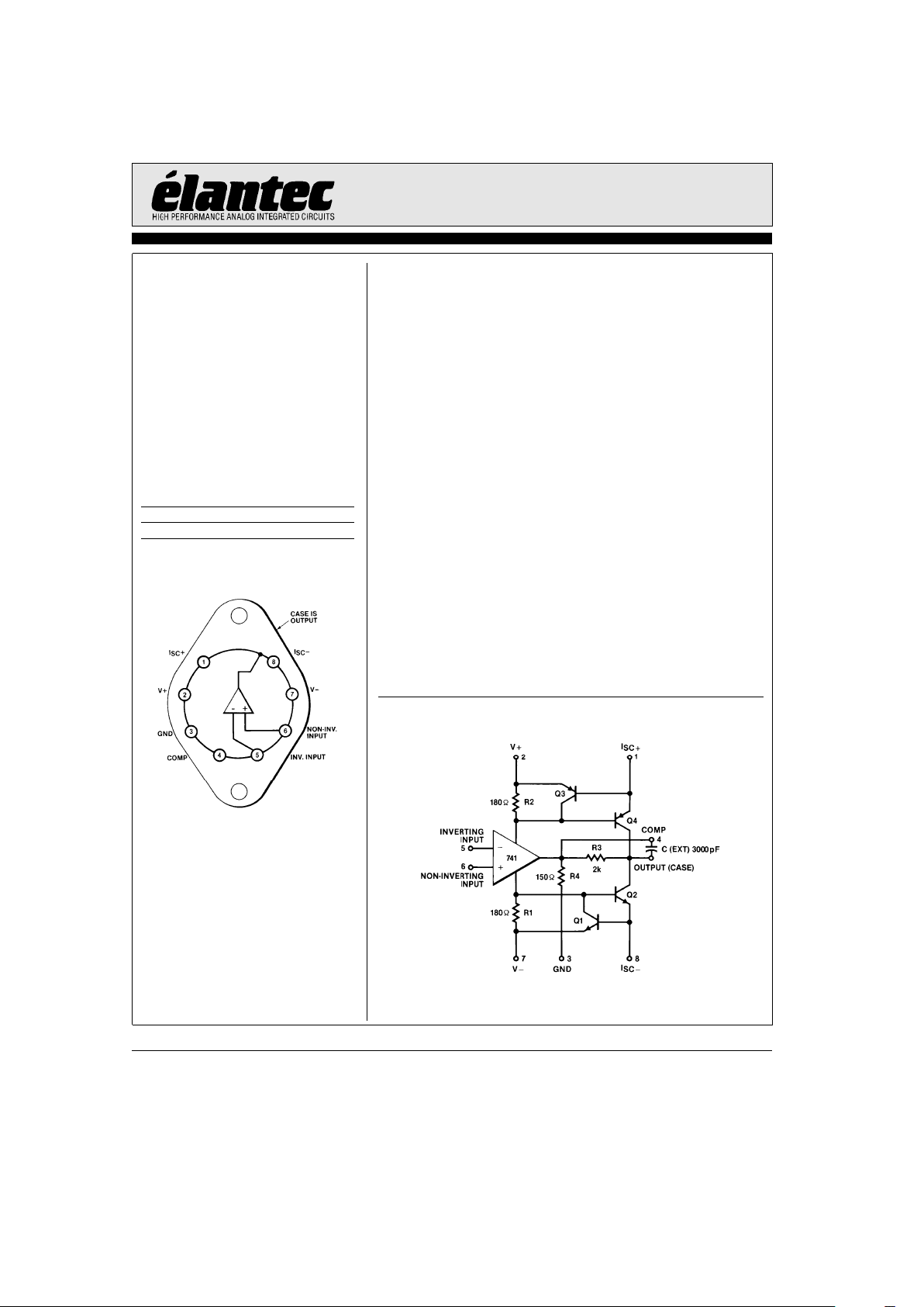
Connection Diagram
0021– 1
Top View
General Description
The ELH0021 is a general purpose operational amplifier capable of delivering large output currents not usually associated
with conventional IC op amps; the ELH0021 will provide output currents in excess of 1A at voltage levels of
g
12V. In addition, both the inputs and outputs are protected against overload. The device is compensated with a single external capacitor
and are free of any unusual oscillation or latch-up problems.
The excellent input characteristics and high output capability
of the ELH0021 make it an ideal choice for power applications
such as DC servos, capstan drivers, deflection yoke drivers, and
programmable power supplies.
Other applications include torque drivers for inertial guidance
systems, diddle yoke drivers for alphanumeric CRT displays,
cable drivers, and programmable power supplies for automatic
test equipment.
The ELH0021 is supplied in an 8-pin TO-3 package rated at
20W with suitable heatsink. The ELH0021 is guaranteed over
the temperature range of
b
55§Ctoa125§C.
Elantec facilities comply with MIL-I-45208A and other applicable quality specifications. Elantec’s Military devices are 100%
fabricated and assembled in our rigidly controlled, ultra-clean
facilities in Milpitas, California. For additional information on
Elantec’s Quality and Reliability Assurance policy and procedures request brochure QRA-1.
Equivalent Schematic
0021– 2
Page 2
ELH0021K/883/8508801YX
1 Amp Power Operational Amplifier
Absolute Maximum Ratings
(T
A
e
25§C)
V
S
Supply Voltage
g
18V
V
IN
Input Voltage (Note 1)
g
15V
P
D
Power Dissipation (See Curves)
Differential Input Voltage
g
30V
Peak Output Current (Note 2) 2A
Output Short
Circuit Duration (Note 3) Continuous
T
A
Operating Temperature Range
ELH0021
b
55§Ctoa125§C
T
ST
Storage Temperature
b
65§Ctoa150§C
Lead Temperature
(Soldering, 10 seconds) 300
§
C
Important Note:
All parameters having Min/Max specifications are guaranteed. The Test Level column indicates the specific device testing actually
performed during production and Quality inspection. Elantec performs most electrical tests using modern high-speed automatic test
equipment, specifically the LTX77 Series system. Unless otherwise noted, all tests are pulsed tests, therefore T
J
e
T
C
e
TA.
Test Level Test Procedure
I 100% production tested and QA sample tested per QA test plan QCX0002.
II 100% production tested at T
A
e
25§C and QA sample tested at T
A
e
25§C,
T
MAX
and T
MIN
per QA test plan QCX0002.
III QA sample tested per QA test plan QCX0002.
IV Parameter is guaranteed (but not tested) by Design and Characterization Data.
V Parameter is typical value at T
A
e
25§C for information purposes only.
DC Electrical Characteristics
V
S
e
g
15V, T
MIN
s
T
A
s
T
MAX,CC
e
3000 pF
Parameter Description Test Conditions
ELH0021
Units
Min Typ Max
Test
Level
V
OS
Input Offset R
S
s
100X,T
C
e
25§C (Note 4) 1 3 I mV
Voltage
R
S
s
100X (Note 4) 5 I mV
DVOS/DT Voltage Drift R
S
s
100X
325IVmV/
§
C
with Temperature
Offset Voltage Drift T
A
e
25§C
5VmV
0
wk
with Time
DVOS/DP Offset Voltage
Change with 5 15 I mV/W
Output Power
I
OS
Input Offset T
C
e
25§C (Note 4) 30 100 I nA
Current
(Note 4) 300 I nA
Offset Current Drift
0.1 1 IV nA/
§
C
with Temperature
Offset Current Drift T
A
e
25§C
2 V nA/
0
wk
with Time
I
B
Input Bias Current T
C
e
25§C (Note 4) 100 300 I nA
(Note 4) 1 I mA
R
IN
Input Resistance T
C
e
25§C 0.3 1 I MX
CMRR Common-Mode R
S
s
100X,V
CM
e
g
10V
70 90 I dB
Rejection Ratio
V
INCM
Input Voltage
g
12 IV V
Range
2
TDis 4.1in
Page 3
ELH0021K/883/8508801YX
1 Amp Power Operational Amplifier
DC Electrical Characteristics
V
S
e
g
15V, T
MIN
s
T
A
s
T
MAX,CC
e
3000 pF Ð Contd.
Parameter Description Test Conditions
ELH0021
Units
Min Typ Max
Test
Level
PSRR Power Supply R
S
s
100X,V
S
e
g
5V tog15V
80 96 I dB
Rejection Ratio
A
VOL
Voltage Gain V
O
e
g
10V, R
L
e
1kX,T
C
e
25§C 100 200 I V/mV
(Note 5)
V
O
e
g
10V, R
L
e
100X 25 I V/mV
V
O
Output Voltage R
L
e
100X
g
13.5 14 I V
Swing
R
L
e
10X,T
C
e
25§C
g
11
g
12 I V
I
SC
Output Short T
C
e
25§C, R
SC
e
0.5X
0.8 1.2 1.6 I A
Circuit Current
I
S
Supply Current V
OUT
e
0V 2.5 3.5 I mA
P
C
Power V
OUT
e
0V
75 105 I mW
Consumption
Note 1: Rating applies for supply voltages aboveg15V. For supplies less thang15V, rating is equal to supply voltage.
Note 2: Rating applies for ELH0021K with R
SC
e
0X.
Note 3: Rating applies as long as package power rating is not exceeded.
Note 4: Specifications apply for
g
5VsV
S
s
g
18V.
Note 5: The ELH0021, like all Class B amplifiers, has a ‘‘dead band’’ when V
OUT
is near 0V. Typical values for the ‘‘dead band’’ are
in the 50 mVto200mV range. Open-loop gain is measured at V
OUT
fromg0.5 VDCTOg10.0 VDCwhich is out of the range
of the ‘‘dead band’’.
AC Electrical Characteristics
T
A
e
25§C, V
S
e
g
15V, C
C
e
3000 pF
Parameter Description Test Conditions
ELH0021
Units
Min Typ Max
Test
Level
SR Slew Rate A
V
e
1, R
L
e
100X 1.5 3 I V/ms
BW Bandwidth R
L
e
100X 20 V kHz
tr,t
f
Small Signal
0.3 1 I ms
Rise or Fall Time
Small Signal
520 I %
Overshoot
t
S
Settling Time DV
IN
e
10V, A
V
e
1
4Vms
(0.1%)
Overload Recovery
3Vms
Time
HD Harmonic fe1 kHz, P
O
e
0.5W
0.2 V %
Distortion
e
n
Input Noise R
S
e
50X,BWe10 Hz to 10 kHz
5VmVrms
Voltage
i
n
Input Noise Current BWe10 Hz to 10 kHz 0.05 V nA
rms
C
IN
Input Capacitance 3 V pF
3
TDis 2.4inTDis 3.2in
Page 4

ELH0021K/883/8508801YX
1 Amp Power Operational Amplifier
Typical Performance Curves
Power Derating Safe Operating Area Output Voltage Swing
Frequency Response
Open-Loop
Frequency Response
Large Signal
Pulse Response
Voltage Follower
No Load Supply Current vs Temperature
Short Circuit Current
Input Bias Current
0021– 3
4
Page 5

ELH0021K/883/8508801YX
1 Amp Power Operational Amplifier
Typical Performance Curves
Ð Contd.
Voltage Gain
Input Current Input Voltage Range
Input Noise Voltage Input Noise Current
Distortion vs Frequency
0021– 4
Typical Applications
CRT Deflection Yoke Driver
0021– 5
DC Servo Amplifier
0021– 6
5
Page 6

ELH0021K/883/8508801YX
1 Amp Power Operational Amplifier
Typical Applications
Ð Contd.
Unity Gain with Short Circuit Limiting
0021– 7
Offset Voltage Null Circuit
0021– 8
Operation from Single Supplies
Positive
0021– 9
Negative
0021– 10
Operation from Non-Symmetrical Supplies
0021– 11
0021– 12
6
Page 7

ELH0021K/883/8508801YX
1 Amp Power Operational Amplifier
Burn-In Circuit
0021– 13
7
Page 8

ELH0021K/883/8508801YXJuly 1991 Rev G
ELH0021K/883/8508801YX
1 Amp Power Operational Amplifier
General Disclaimer
Specifications contained in this data sheet are in effect as of the publication date shown. Elantec, Inc. reserves the right to make changes
in the circuitry or specifications contained herein at any time without notice. Elantec, Inc. assumes no responsibility for the use of any
circuits described herein and makes no representations that they are free from patent infringement.
Elantec, Inc.
1996 Tarob Court
Milpitas, CA 95035
Telephone: (408) 945-1323
(800) 333-6314
Fax: (408) 945-9305
European Office: 44-71-482-4596
WARNING Ð Life Support Policy
Elantec, Inc. products are not authorized for and should not be
used within Life Support Systems without the specific written
consent of Elantec, Inc. Life Support systems are equipment intended to support or sustain life and whose failure to perform
when properly used in accordance with instructions provided can
be reasonably expected to result in significant personal injury or
death. Users contemplating application of Elantec, Inc. products
in Life Support Systems are requested to contact Elantec, Inc.
factory headquarters to establish suitable terms & conditions for
these applications. Elantec, Inc.’s warranty is limited to replacement of defective components and does not cover injury to persons or property or other consequential damages.
Printed in U.S.A.8
 Loading...