

Page 1
EL7232C
Dual Channel, High Speed, High Current Line Driver w/3-State
EL7232C January 1996 Rev. B
Features
# 3-State output
# 3V and 5V input compatible
# Clocking speeds up to 10 MHz
# 20 ns Switching/delay time
# 2A Peak drive
# Low, matched output
impedanceÐ5X
# Low quiescent currentÐ2.5 mA
# Wide operating voltageÐ
4.5V--16V
Applications
# Parallel bus line drivers
# EPROM and PROM
programming
# Motor controls
# Charge pumps
# Sampling circuits
# Pin drivers
# Bridge circuits
Ordering Information
Part No. Temp. Range Pkg. Outline
EL7232CNb40§Ctoa85§C 8-Pin P-DIP MDP0031
EL7232CSb40§Ctoa85§C 8-Pin SO MDP0027
General Description
The EL7232C 3-state drivers are particularly well suited for
ATE and microprocessor based applications. The low quiescent
power dissipation makes this part attractive in battery applications. The 2A peak drive capability, makes the EL7232C an
excellent choice when driving high speed capacitive lines, as
well. The input circuitry provides level shifting from TTL levels to the supply rails. The EL7232C is available in 8-pin P-DIP
and 8-lead SO packages.
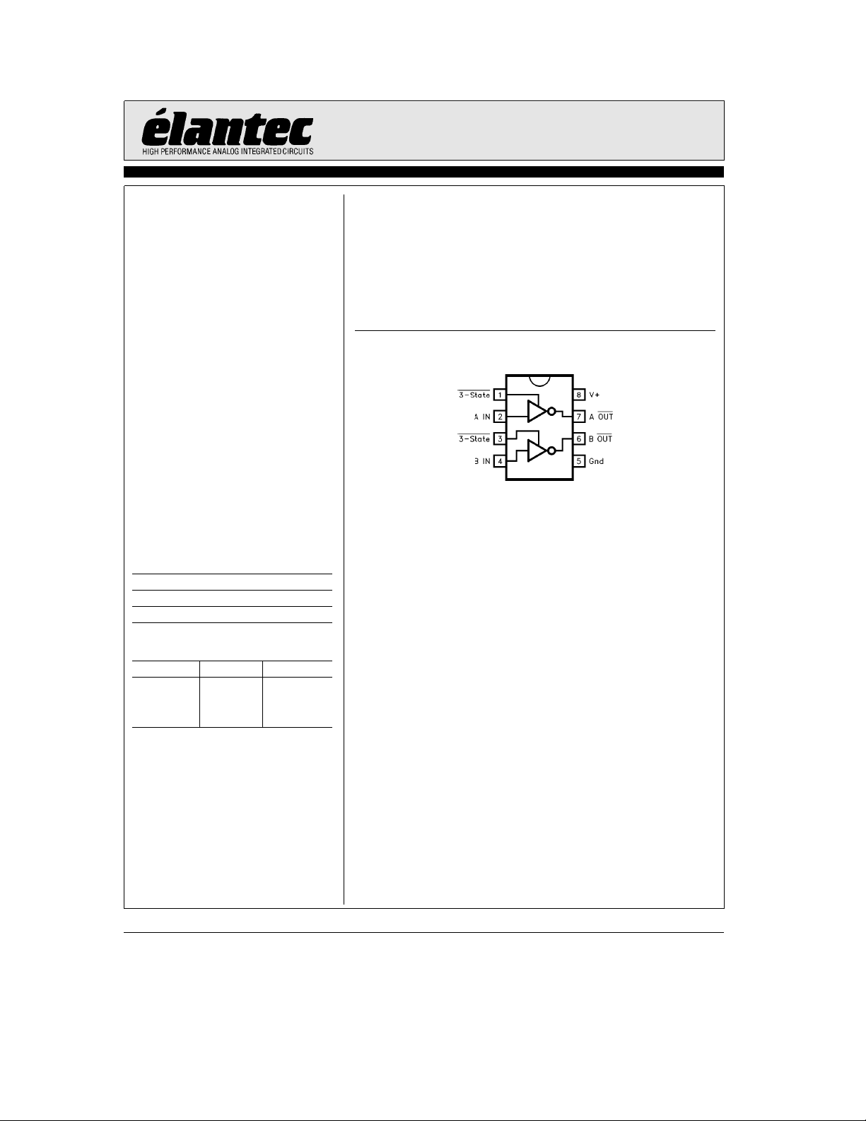
Connection Diagram
7232– 1
Ý
Truth Table
3-State Input Output
101
110
0 0 Open
0 1 Open
Manufactured under U.S. Patent Nos. 5,334,883,Ý5,341,047
Note: All information contained in this data sheet has been carefully checked and is believed to be accurate as of the date of publication; however, this data sheet cannot be a ‘‘controlled document’’. Current revisions, if any, to these
specifications are maintained at the factory and are available upon your request. We recommend checking the revision level before finalization of your design documentation.
©
1994 Elantec, Inc.
Page 2
EL7232C
Dual Channel, High Speed, High Current Line Driver w/3-State
Absolute Maximum Ratings
Supply (Vato Gnd) 16.5V
Input Pins
b
0.3V toa0.3V above V
Combined Peak Output Current 4A
Storage Temperature Range
Ambient Operating Temperature
Important Note:
All parameters having Min/Max specifications are guaranteed. The Test Level column indicates the specific device testing actually
performed during production and Quality inspection. Elantec performs most electrical tests using modern high-speed automatic test
equipment, specifically the LTX77 Series system. Unless otherwise noted, all tests are pulsed tests, therefore T
Test Level Test Procedure
I 100% production tested and QA sample tested per QA test plan QCX0002.
II 100% production tested at T
III QA sample tested per QA test plan QCX0002.
IV Parameter is guaranteed (but not tested) by Design and Characterization Data.
V Parameter is typical value at T
T
MAX
and T
MIN
DC Electrical Characteristics
Parameter Description
b
65§Ctoa150§C
b
40§Ctoa85§C
e
25§C and QA sample tested at T
A
per QA test plan QCX0002.
e
25§C for information purposes only.
A
e
T
A
Conditions Level
Input
V
I
V
I
V
IH
IH
IL
IL
HVS
Logic ‘‘1’’ Input Voltage 2.4 I V
@
Logic ‘‘1’’ Input Current
a
V
Logic ‘‘0’’ Input Voltage 0.8 I V
Logic ‘‘0’’ Input Current
@
0V 0.1 10 I mA
Input Hysteresis 0.3 V V
Output
R
R
I
I
I
OH
OL
OFF
PK
DC
Pull-Up Resistance I
Pull-Down Resistance I
3-State Output Leakage V
OUT
OUT
V
OUT
OUT
Peak Output Current Source 2.0
Sink 2.0
Continuous Output Current Source/Sink 100 I mA
Power Supply
I
S
V
S
Power Supply Current Inputs High 1 2.5 I mA
Operating Voltage 4.5 16 I V
Operating Junction Temperature 125
a
Power Dissipation
SOIC 570 mW
PDIP 1050 mW
e
T
J
e
25§C,
A
25§C, Ve15V unless otherwise specified
Test
Min Typ Max
Test
0.1 10 I mA
eb
100 mA 3 6 I X
ea
100 mA 4 6 I X
eVa
e
0V
0.2 10 I mA
IV A
§
e
TA.
C
Units
C
TDis3.4in
2
Page 3
EL7232C
Dual Channel, High Speed, High Current Line Driver w/3-State
AC Electrical Characteristics
Parameter Description
Switching Characteristics
t
R
t
F
t
D-ON
t
D-OFF
Rise Time C
Fall Time C
Turn-On Delay Time 18 25 IV ns
Turn-Off Delay Time 20 25 IV ns
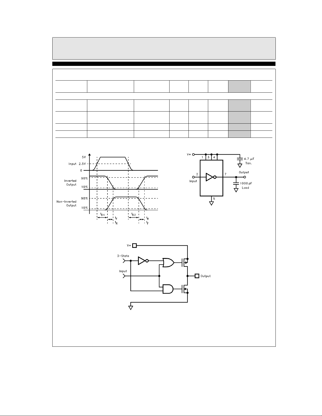
Timing Table
e
T
25§C, Ve15V unless otherwise specified
A
Test
Conditions Level
e
500 pF 7.5
L
e
C
1000 pF 10
L
e
500 pF 10
L
e
C
1000 pF 13 20
L
Min Typ Max
Test
Standard Test Configuration
7232– 2
Units
IV ns
IV ns
TDis1.5in
7232– 3
Simplified Schematic
3
7232– 4
Page 4
EL7232C
Dual Channel, High Speed, High Current Line Driver w/3-State
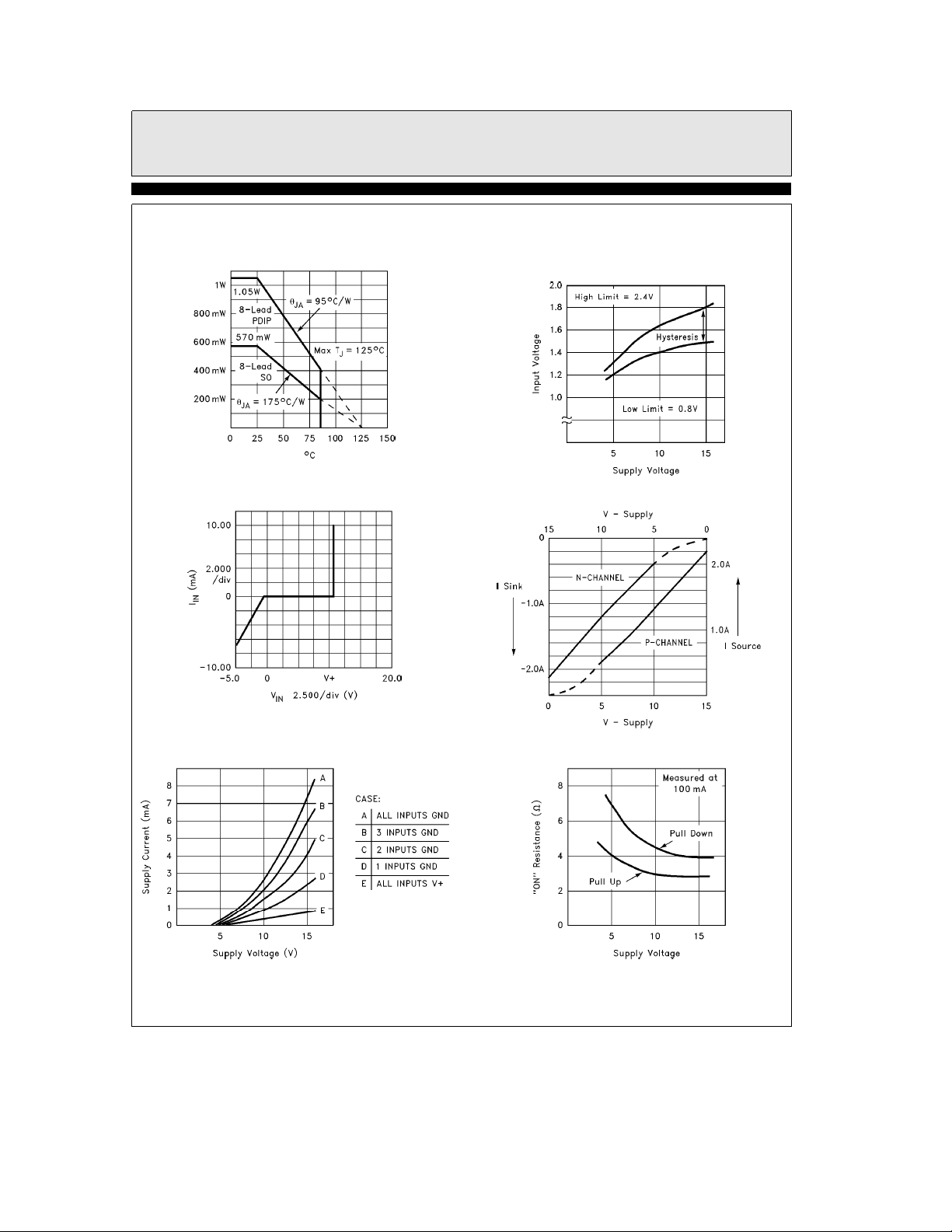
Typical Performance Curve
Max Power/Derating Curves
Input Current vs Voltage
Quiescent Supply Current
7232– 6
7232– 8
Switch Threshold vs
Supply Voltage
Peak Drive vs Supply Voltage
‘‘ON’’ Resistance vs Supply Voltage
7232– 7
7232– 9
4
7232– 10
7232– 17
Page 5
EL7232C
Dual Channel, High Speed, High Current Line Driver w/3-State
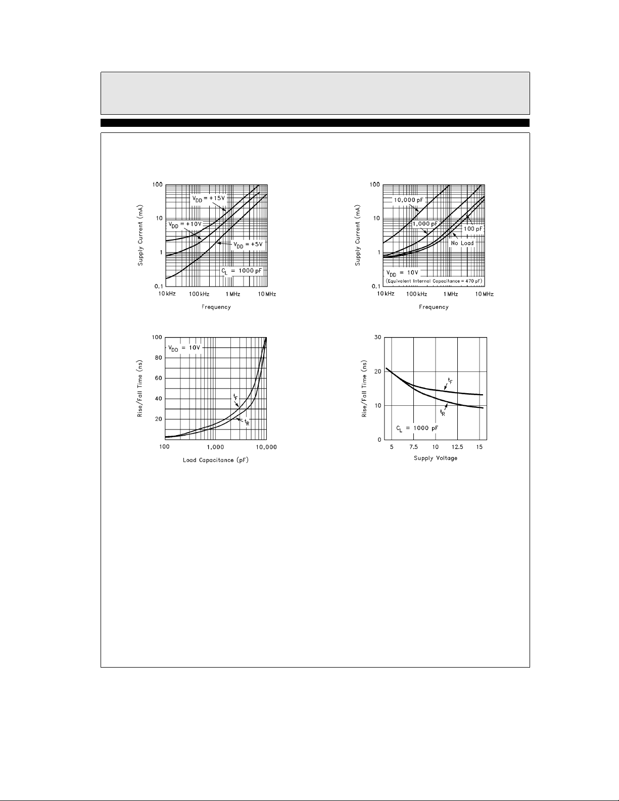
Typical Performance Curve
Average Supply Current vs
Voltage and Frequency
Rise/Fall Time vs Load
Ð Contd.
7232– 11
Average Supply Current
vs Capacitive Load
Rise/Fall Time vs Supply Voltage
7232– 12
7232– 5
7232– 13
5
Page 6
EL7232C
Dual Channel, High Speed, High Current Line Driver w/3-State
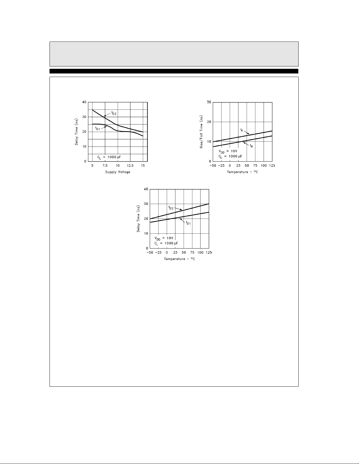
Typical Performance Curve
Rise/Fall Time vs Temperature
Ð Contd.
7232– 14
Propagation Delay vs Temperature
Propagation Delay vs Supply Voltage
7232– 15
7232– 16
6
Page 7

BLANK
7
Page 8
EL7232C
Dual Channel, High Speed, High Current Line Driver w/3-State
EL7232CJanuary 1996 Rev. B
General Disclaimer
Specifications contained in this data sheet are in effect as of the publication date shown. Elantec, Inc. reserves the right to make changes
in the circuitry or specifications contained herein at any time without notice. Elantec, Inc. assumes no responsibility for the use of any
circuits described herein and makes no representations that they are free from patent infringement.
WARNING Ð Life Support Policy
Elantec, Inc. products are not authorized for and should not be
used within Life Support Systems without the specific written
consent of Elantec, Inc. Life Support systems are equipment in-
Elantec, Inc.
1996 Tarob Court
Milpitas, CA 95035
Telephone: (408) 945-1323
(800) 333-6314
Fax: (408) 945-9305
European Office: 44-71-482-4596
tended to support or sustain life and whose failure to perform
when properly used in accordance with instructions provided can
be reasonably expected to result in significant personal injury or
death. Users contemplating application of Elantec, Inc. products
in Life Support Systems are requested to contact Elantec, Inc.
factory headquarters to establish suitable terms & conditions for
these applications. Elantec, Inc.’s warranty is limited to replacement of defective components and does not cover injury to persons or property or other consequential damages.
Printed in U.S.A.8
 Loading...