

Page 1

Embedded Display Module
EDM6070AR-01
Atmel AT91SAM9X35 Based Single Board Computer
BY
User Manual
Version 1.0
Dated: 3
rd
December 2013
Page 2

Revision Histo r y:
Version Date Description
1.0
03/12/2013
Original Version
Page 3

Table of Contents
Chapter 1: Product Overview............................................. 1
1.1 Introduction ............................................................. 1
1.2 Kit Contents ............................................................. 3
1.3 Expansion Board Interfaces ........................................ 4
1.4 Core Board Interfaces ................................................ 4
1.5 System Block Diagram ............................................... 6
1.6 Physical Dimensions (mm ) ......................................... 7
Chapter 2: Hardware Features .......................................... 8
2.1 Processor ................................................................. 8
2.2 On-Board Mem ory ..................................................... 8
2.3 On-Board Interfaces .................................................. 8
2.4 Others ..................................................................... 9
2.5 Operation al Paramet ers.............................................. 9
Chapter 3: Software Features .......................................... 10
3.1 BSP Package........................................................... 10
3.2 Example Applications ............................................... 11
3.3 API Functions ......................................................... 12
Chapter 4: Demonstrat ion and Test Functions ................. 16
4.1 Smart Home Automation Demo................................. 16
4.1.1 Demo Features .................................................. 17
4.1.2 Progra mming the demo ...................................... 21
4.2 System Setup ......................................................... 23
4.3 Testing Features ...................................................... 24
4.3.1 Touchscreen Test ............................................... 24
4.3.2 LCD Col our Test ................................................. 24
4.3.3 LCD Backlight Test ............................................. 25
4.3.4 Ethernet Test .................................................... 25
4.3.5 Serial Interface (RS232) Test .............................. 26
4.3.6 CAN Bus Test .................................................... 27
Page 4

4.3.7 RS485 Bus Test ................................................. 28
4.3.8 USB Test ........................................................... 29
4.3.9 RTC Test ........................................................... 30
4.3.10 TF Card Test .................................................. 31
4.3.11 LED Test ....................................................... 32
4.3.12 Buzzer Test ................................................... 32
4.3.13 GPIO Test...................................................... 32
4.3.14 Button Test ................................................... 33
4.3.15 Screen Capture Test ....................................... 34
4.3.16 Audio Test ..................................................... 34
4.3.17 Watchdog Test ............................................... 35
4.3.18 Telnet Test .................................................... 35
4.3.19 Mounting NFS (Network File System) ................ 38
4.4 Transferring Files Using SecureCRT ............................ 39
4.5 Transferring File s Using Network Protocol ................... 40
4.6 Linux QT Demonstration........................................... 42
Chapter 5: Development Environment and System
Compilation……………… ....................................................... 44
5.1 Building a Cross Compilation Environment .................. 44
5.2 System Compilation ................................................ 45
5.3 Uncompressing Files ................................................ 45
5.4 Making a Bootstrap ................................................. 46
5.5 Making a U-boot ..................................................... 47
5.6 Making a Kernel ...................................................... 47
5.7 Making a File system Image ..................................... 48
Chapter 6: System Customization .................................... 49
6.1 Kernel Customisation ............................................... 49
6.2 File system Customisation ........................................ 51
6.3 Simple Driver Modu les in K er ne l ................................ 52
6.4 Using Makefil e to Associate Drivers with Kerne l ........... 55
6.5 Compiling and Downloading Drivers........................... 55
Page 5

6.6 Brief In t rod u c tion to Appli c ations .............................. 56
6.7 Compiling and Running Applications .......................... 57
6.8 Common Functions .................................................. 58
6.9 Linux Multi-Thread Programming ............................... 59
6.10 Linux Network Programming ..................................... 61
6.11 Compiling Server .................................................... 64
6.12 Compiling Client ...................................................... 64
6.13 Running Serv er and Client ........................................ 65
Chapter 7: Updating the Linux System ............................ 66
7.1 Images and the Programming Tool ............................ 66
7.1.1 Programming System Image Automatically ........... 67
7.1.2 Programming System Image Manually .................. 69
7.2 Preparations ........................................................... 69
7.3 Programming Image Files ......................................... 71
Chapter 8: Appendix A: Common u-boot Instructions ..... 76
Page 6

Page | 1
Chapter 1: Product Overview
1.1 Introduction
The EDM6070AR-01 is an ARM based Single Board Computer (SBC),
designed & develo p ed b y el emen t14. It comprises of a 7” LCD display and
touch screen assembly, integrated with multi-functional embedded
hardware based on Atmel’s ARM9 AT91SAM9X35 industrial processor.
The EDM6070AR-01 is a fully integrated Embedded Display Module solution
for a variety of embedded control HMI applications, re ady t o drop in to your
product with negligible integration effort, OR to just wrap an enclosure
around, add a software application and become your finished product.
The EDM6070 is designed to fulfil the different requirements of various HMI
applications including:
Industrial control terminals
Intelligent instruments
Data acquisition and analysi s
Medical products
Network terminals.
The EDM6070AR-01 consists of three parts: a MINI6935 CPU core m o d ule,
an expansion board, and a 7” TFT LCD (800×480) with resistive touch
screen
.
MINI6935 CPU module is an ARM embedded board,
integrated with the ATMEL ARM926EJ-S-based processor
AT91SAM9X35, operating at 400MHz frequency. The board has
128MB DDR2 SDRAM, 256MB NAND Flash, 4MB DataFlash, 4KB
Two-wire EEPROM.
Page 7

Page | 2
The Base Board expands the rich set of connectivity and user
interface peripherals of the Atmel AT91SAM9X35 incl uding Ethernet
and CAN interfac e. The bo ard also has a TFT touch screen LCD
interface, USB hosts/device, Buzzer, RS232, RS485, Audio, GPIOs
and an SD car d interf ace to allow for large storage capabilities.
LCD Touch screen Display is a 4-wire resistive touch screen
TFT LCD display with a display resolution of up to 800x480 with
24-bit colour depth.
The EDM6070AR-01 includes Linux BSP and supports the Linux QT GUI
(Graphical User Interface) and multiple file systems like, FA T, NTFS etc. It is
also supplied with a Smart Home demo application (include smart-led
controller, weather c o ntrol ler, video) and a number of example appli c ations
to give you a quick and easy s tart.
Page 8

Page | 3
1.2 Kit Contents
The EDM6070AR-01 SBC is packed with the items listed below:
MINI6935 CPU Process Board based on AT91SAM9X35 MCU
Expansion Base Board
7” Touchscreen LCD Display
Product DVD/CD includes BSP, demo application & technical
documentation.
Optional Accessories (must be purchased separately):
Serial Cable (Cross Over Female-to-Female)
Ethernet Cable
MicroUSB Cable
Serial Interface Adapter
Power Adapter (12V@1.25A)
Page 9
Page | 4
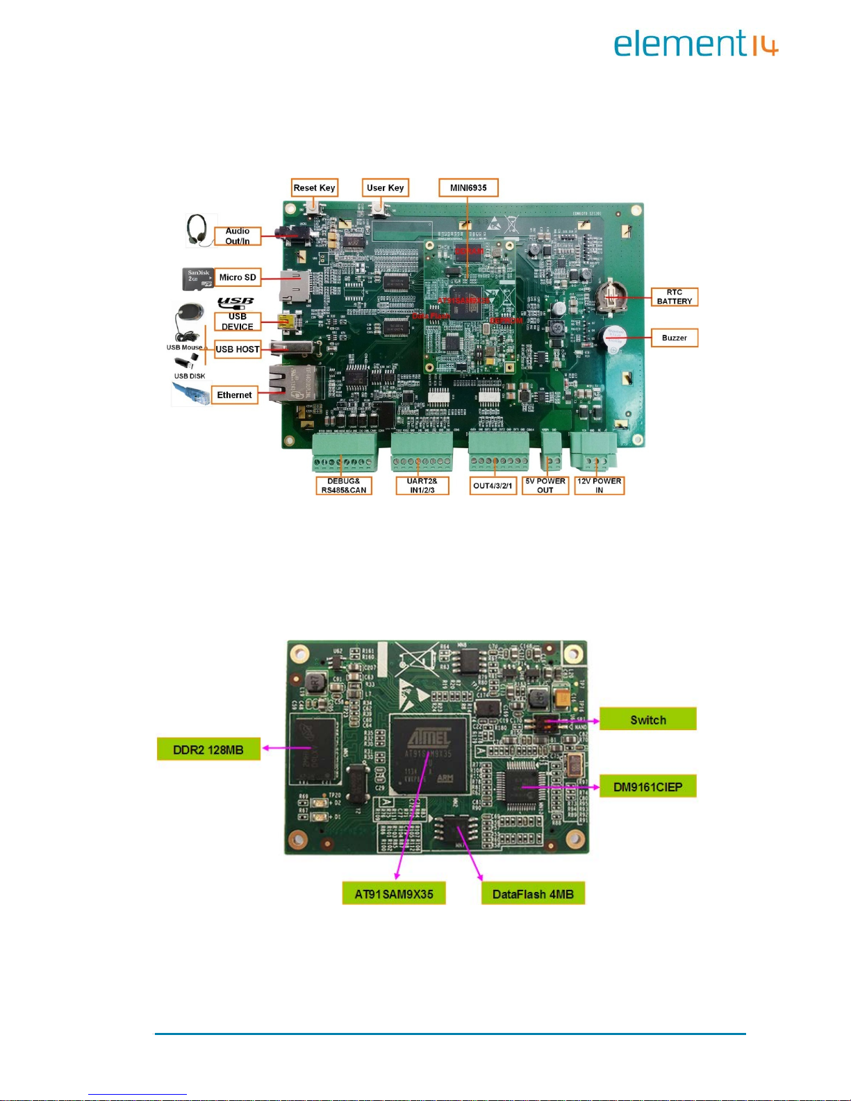
1.3 Expansion Board Interfaces
Figure 1: Base Board Interface with Mounted CPU Module
1.4 Core Board Interfaces
Figure 2: MINI6935 CPU Module (Front View )
Page 10
Page | 5
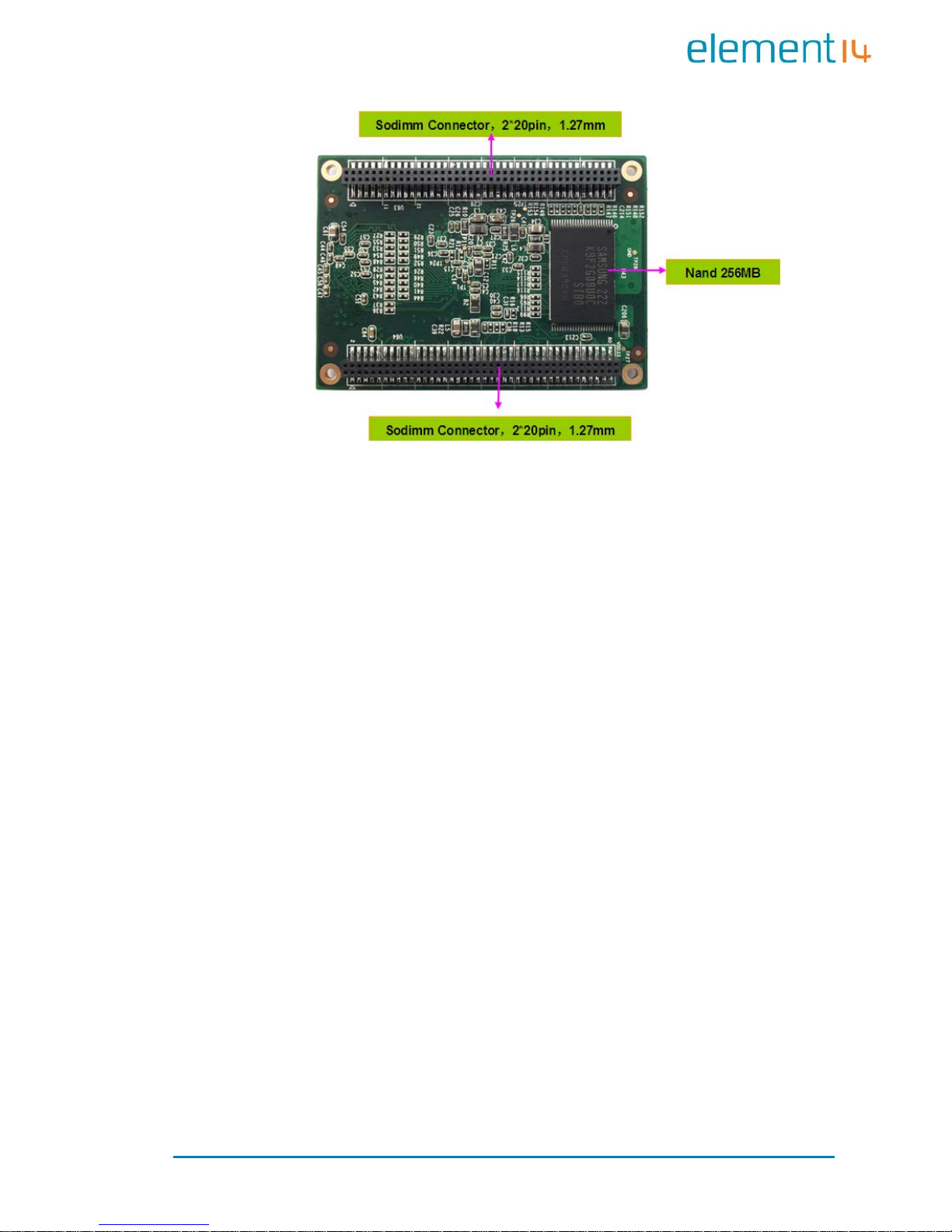
Figure 3: MINI6935 CPU Module (Rear View)
Page 11
Page | 6
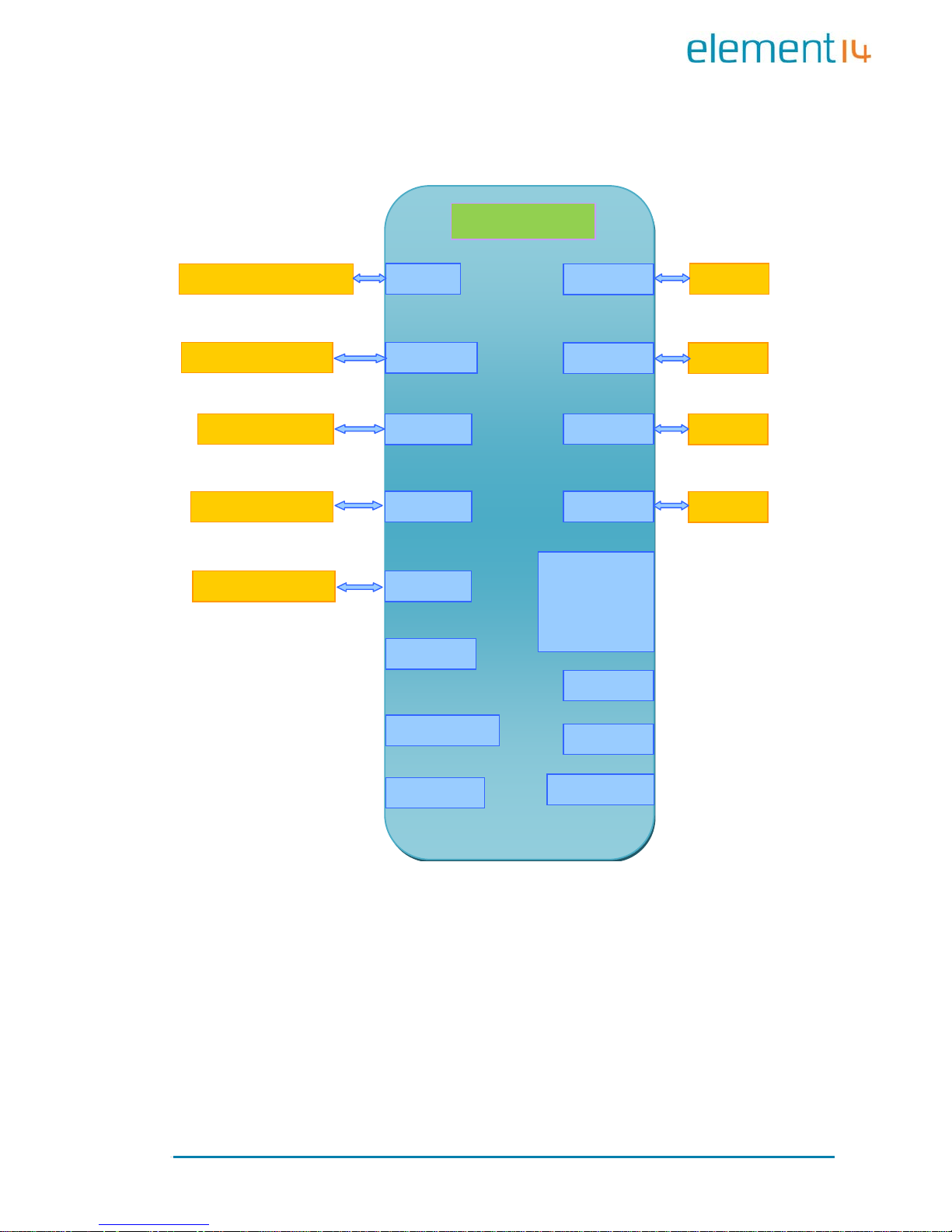
1.5 System Block Diagram
MAC
DM916
Data
AT25DF32 1 32MB
NAND
K9F2G08U0
TWI
AT24C04BN
AT91SAM9X35
RTC
Watchdog
Key
Reset
SD CARD
USB Device
USB Host
GPIO
ISO
LCD
800x480 RGB 7
Audio
RS232
Debug
Port
CAN 2.0
ISO
RS485
ISO
DDR2
MT47H64M16HR
Figure 4: Syst em Blo c k Diag ra m
Page 12
Page | 7
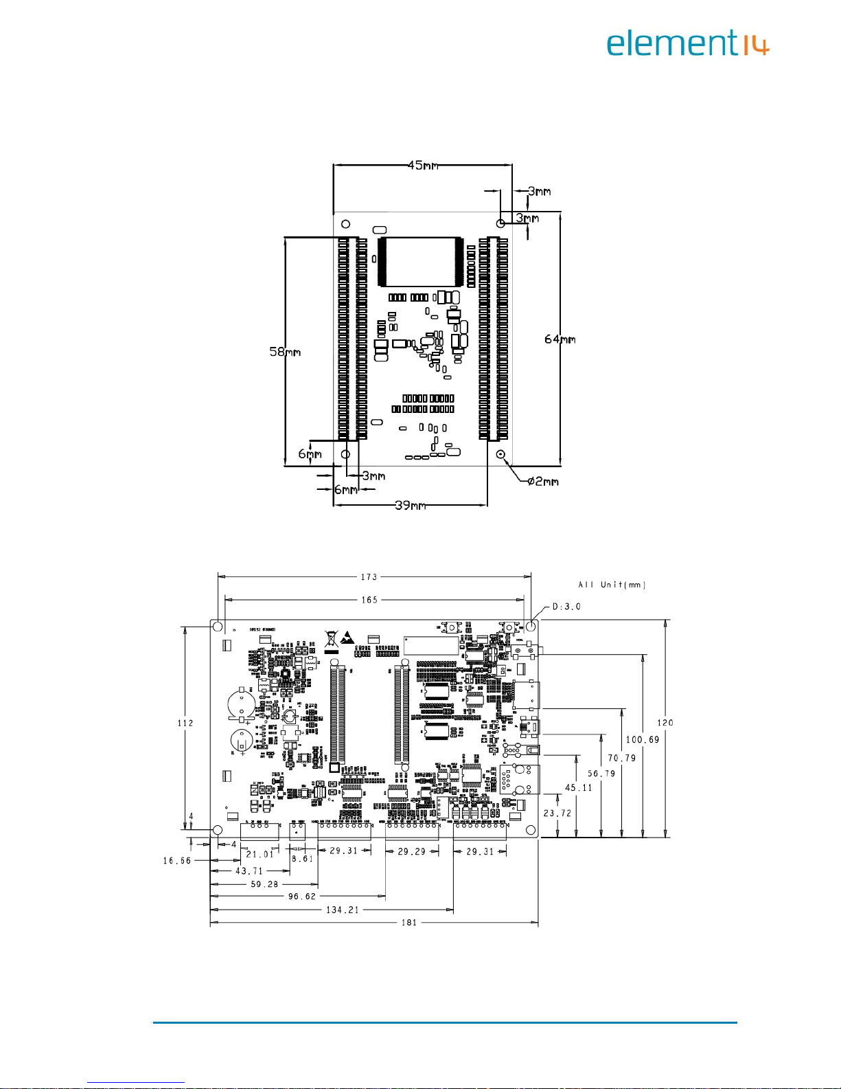
1.6 Physical Dimensions (mm)
Figure 5: Mini6935 Dimension s
Figure 6: Expansion Board Dimensions
Page 13

Page | 8
Chapter 2: Hardware Features
2.1 Processor
Atmel AT91SAM9X35 ARM9 32-bit processor, 400MHz
16KB data cache, 16KB inst ruction cache, memory management
unit
64KB internal ROM and 32KB internal SRAM
2.2 On-Board Memory
128MB DDR2 SDRAM
256MB NAND Flash
4MB DataF lash
2.3 On-Board Interfaces
7” TFT LCD display, resolution of 800x480 with 24-bit colour depth
10/100Mbps Ethernet interface, using a DM9161CIEP chip,
extendable via expansion board
RS232 interface, 1 RS485 interface, 1 CAN interface
USB Host hi gh-speed interface
USB Device interface
Three GPIO Input interfaces
Four GPIO Output interfaces
Audio output interface, supportin g M P3 playback
Debugging Int erface, extendable via ex pansion board
TF card slot
Page 14

Page | 9
2.4 Others
I/O interface LED indicator, 2 LED power indicators
Buzzer
I/O button
Reset button
RTC (no battery by default)
Watchdog
2.5 Operational Parameters
Operating Temperature: -10 °C ~ 70 °C
Operating Humidity: 0% ~ 90% (Non-condensing)
Power Supply: 12V@1.25A
Electrical Standards: CE, FCC and CCC
Product Dimensions: 181mm x 120mm
Page 15

Page | 10
Chapter 3: Software Features
This chapter will briefly introduce the BSP package in the CD-ROM, example
applic ation s insta lled in the p rodu ct an d the AP I functions called by thes e
applications.
3.1 BSP Package
The CD-ROM provided with the EDM6070 co ntains a BSP (Board Support
package) which is used for building custom Linux systems. The table shown
below lists the contents of the BSP with corresponding descriptions.
Types Names Description
BIOS
Bootstrap Serial Flash
U-Boot
Serial Flash
Supports kernel and file system programming through
SAM-BA or USB fl ash drive (USB flash driv e is
recommended)
Device
Drivers
Serial Debugging and COM2 serial interface on CPU
RTC
Internal RTC of AT91SAM 9X35
Ethernet
10/100M Ethernet driver
Flash
NAND Flash and DataFlash driver
LCD
LCD driver, 800x480 resolution
Touch
Screen
Touchscreen controller on CPU
USB Host
USB Host driver
Watchdog
Built-in watchdog driver
SD Card
SD card driver
CAN Bu s
CAN bus
RS-485
RS-485 bus
LED Syste m sta tu s LED
BEEP
B
uzz er driver
Audio WM8731EDS audio output driver
Button Custom user button driver
GPIO GPIO driver, 3 input chan ne l s , 4 output channels
Kernel Linux-2.6.39 ROM/CRAM/EXT2/EXT3/FAT/NFS/JFFS2/YAFFS2/UBIFS
Page 16
Page | 11
Types
Names
Description
file syst ems
Root File
System
UBIFS
Readable and writeable file system, supporting
compression storage
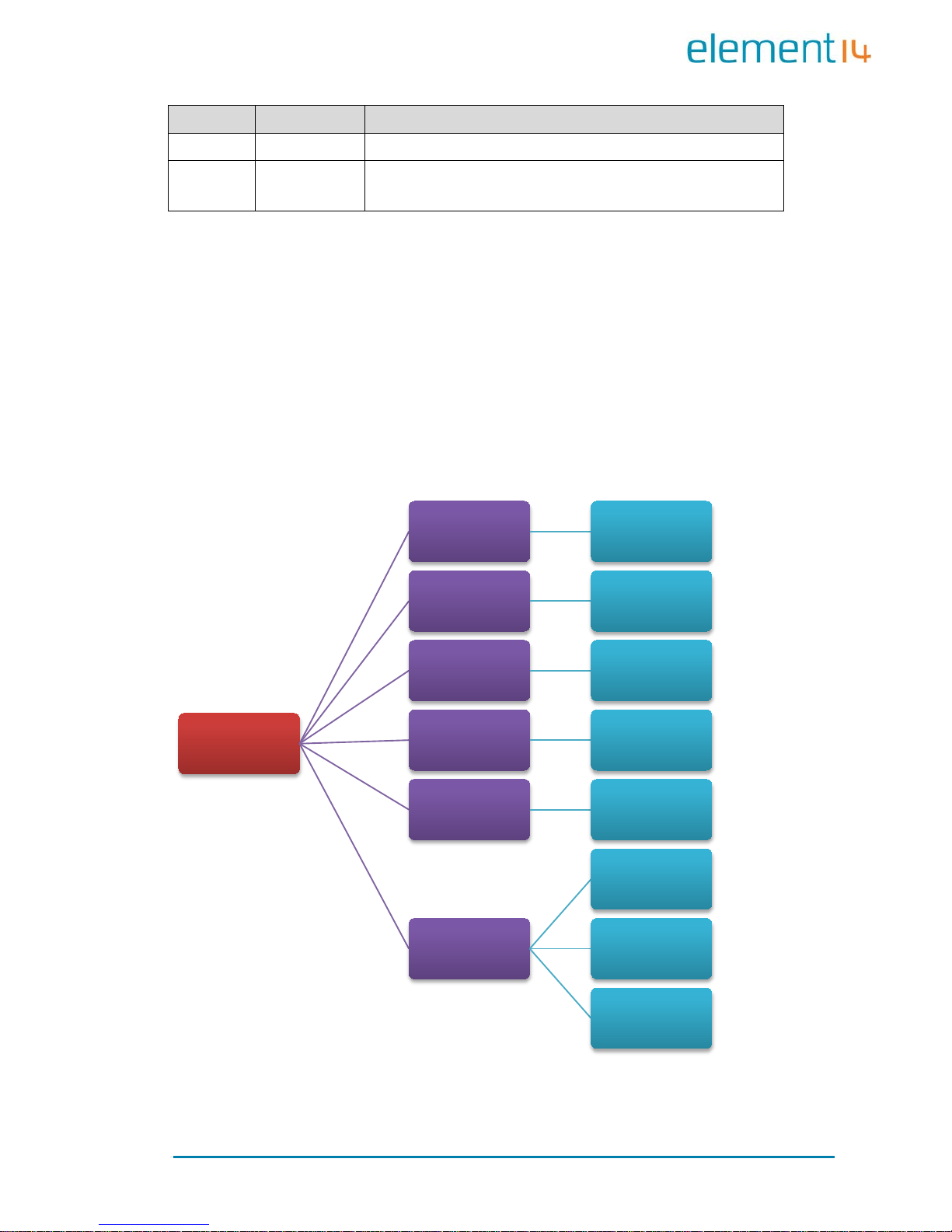
3.2 Example Applications
The Linux system installed in EDM6070 contains multiple example
applications under /home/app. Users can use those applications to
implement, test or demonstrate various product functionalities. The
following block diagram clearly shows the location of each example
application in the system.
Figure 7: Example App l ic ations (D irectory Str uc ture)
/home/app
COM UART Test
EVTEST
Event Devices
Test
GPIO GPIO Test
LED LED Test
BEEP Buzzer Test
CAN
CAN Test
CAN Receiver
Test
CAN Transmitter
Test
Page 17

Page | 12
3.3 API Functions
Before you start to test the prod uct, it is necessary to learn about the API
functions used by the example applications. If you need to understand the
work ing princip le of an application in detail, read the source code stored
under “\02 Linux 2.6 Kit\01 Source Code\app\” in the CD-ROM
provided al ong wit h EDM6070.
The tables listed be low will sho w you the API functions called by some of
applications and the relevant information.
LED API Function
LED_API int led_ctrl (char *name, int onoff );
Source ledlib.h
Functionalities Turn on or off LEDs
Parameters
Name (LED’s name such asD6, D9 or D13)
onoff (0 for off, 1 for on)
Returned Values 0 for success, otherwise fail u r e
Examples led_ctrl ("D9", 1);
Buzzer API
Function
BEEP_API int beep_ctrl (char *name, int onoff);
Source beeplib.h
Functionalities Controls the buzzer to make sound or stop
Parameters
Name (buzzer name, normally there is only
one buzzer which is called “beep”)
onoff (0 for off, 1 for on)
Returned Values 0 for success, otherwise failure
Examples beep_ctrl ("beep", 1); beep_ctrl ("beep", 0);
Serial Interface
API Function
int OpenDev(char *Dev);
Source com_example.c
Functionalities Enable s erial d evices and acquire descriptors
Page 18

Page | 13
Parameters
dev (character string of
serial devices, e.g.
“/dev/ttySAC0”)
Values more than 0 is a serial file descriptor,
less than 0 stands for failu r e
Returned Values com_example.c
void set _ s pe ed(int f d, in t s peed);
Source com_example.c
Functionalities Set the bitrate o f seri al interfaces
Parameters
fd (serial file descriptor)
speed (bitrate, e.g. 15200)
Returned Values None
int set_Parity(int fd ,int databits,int stop bit s,int parit y,i nt
flowctrl);
Source com_example.c
Functionalities
Set serial interface
data bits, stop bits, parity
check an d data flo w co nt rol
Parameters
fd (serial file descriptor)
databits (length o f data bit s)
stopbits (length of stop bits)
parity
(check type, N for no check, O for odd
check, E for even check)
flowctrl
(switch of hardware data follow
control, 1 for enable, 0 for disable)
Returned Values 0 for success, o t herwise failure
size_t read(int fd, const void *buf, size_t nbytes);
Source unistd.h
Functionalities
Called by system to acquire data received on
the serial interfaces
Parameters
fd (serial file descriptor)
buf (pointer t o t he rec eived data)
nbytes (data length about to be read, Byte)
Returned Values
Valu es less t han 0 stands for error, more than
0 stands for received data l ength (Byte)
size_t write(int fd, const void *buf, size_t nbytes);
Source unistd.h
Functionalities
Called by system to send data through the
serial interfaces
Parameters fd (serial file descriptor)
Page 19

Page | 14
buf (pointer to the data about to be sent)
nbytes (length of data about to be sent, Byte)
Returned Values
Value of less than 0 stand s for an error, more
than 0 stands for a
data length being sent
(Byte)
int close(int fd);
Source unistd.h
Functionalities
Called by system to disable the serial
interfaces
Parameters fd (serial file descriptor)
Returned Values 0 for success, less than 0 stands fo r er ror
GPIO API Function
int open(const char *path, int oflags);
Source gpio_example.c
Functionalities Initialize the GPIO device no de
Parameters Path: /dev/gpio.0 oflags: O_RDWR
Returned Values 0 for success, o t herwise failure
int close(int fildes);
Source gpio_example.c
Functionalities Releas e GPIO
Parameters fildes: open returned file descriptor
Returned Values 0 for success, o t herwise failure
ioctl(fd, GPIO_GET_VALUE, pin);
Source gpio_example.c
Functionalities Read the logic level of the input pin
Parameters
Pin (GPIO pin name , such as GPIO_PB15)
fd (GPIO device descriptor)
Returned Values Return level value in digit 0 or 1
ioctl(fd, GPIO_S ET_ PI N, pin);
Source gpio_example.c
Functionalities
Allow the output pin provide a
high level
output
Parameters Pin (GPIO pin name, such as GPIO_PD18)
Returned Values None
Page 20

Page | 15
ioctl(fd, GPIO_ CLR_ PIN , pin );
Source gpio_example.c
Functionalities
Allow the output pin to provide a
low level
output
Parameters
Pin (GPIO pin name , such as GPIO_PD18)
Returned Values None
Page 21
Page | 16
Chapter 4: Demonstration and Test
Functions
This chap ter will introduce to the S mart Home Automation demo application
and how to use the example applications contained in the system to
implement functionality tests of the EDM6070, as we ll as a demonstr ation of
the LinuxQT graphics interface.
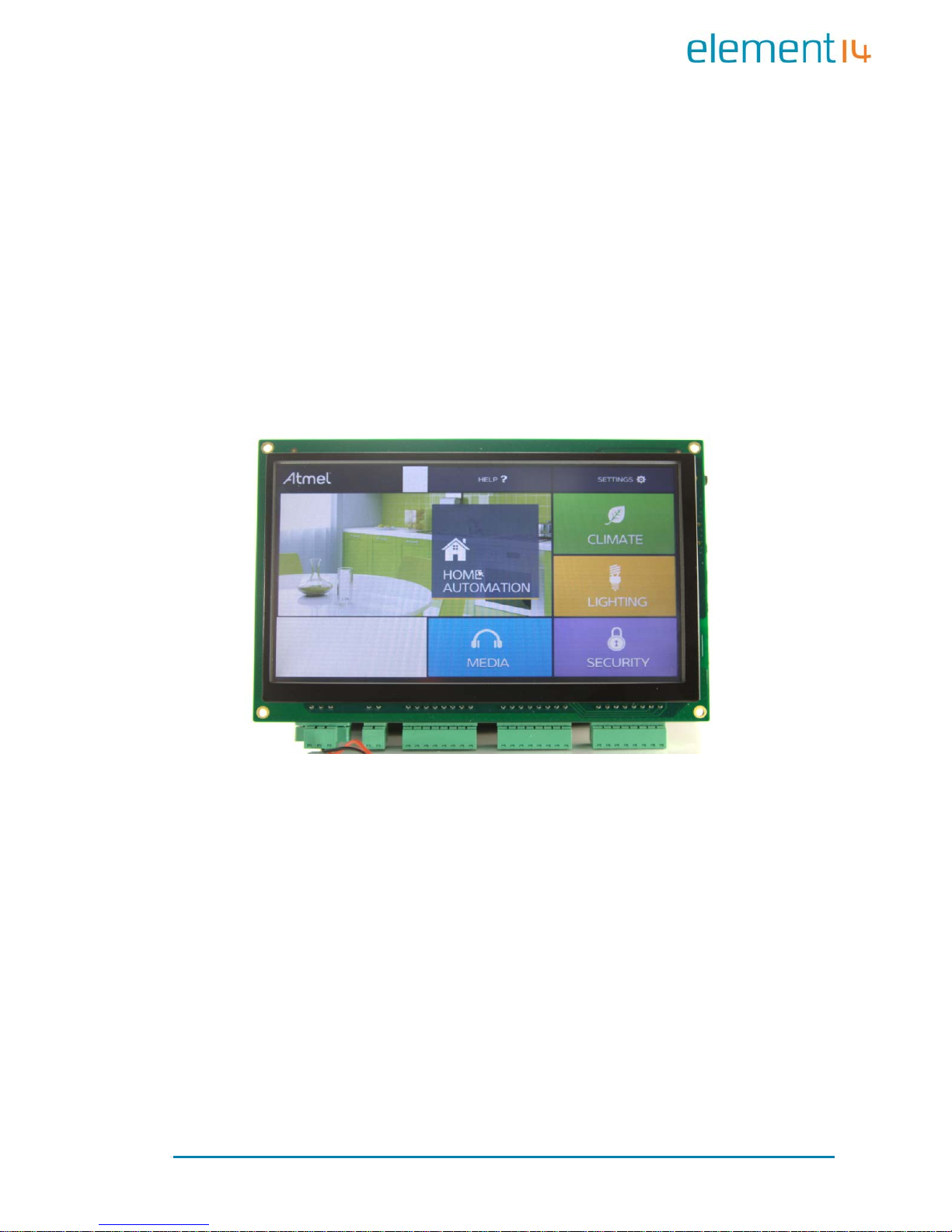
4.1 Smart Home Automation Demo
A Smart Home System demo application has been provided with the
EDM6070. This d emo applica tion enables EDM developers to qu ickly and
easily jumpstart their embedded Linux application development — without
first having to set up their development environment. Smart Home
automati on demo fe atures a Q T GUI appl ication with several custo m widgets,
including:
Climate Control
Light control
Thermostat control
Page 22
Page | 17
Video player
4.1.1 Demo Features
This demo showcases the control of various house functions including
heating, lighting, security and a media player. The major functions are
expounde d upon be lo w:
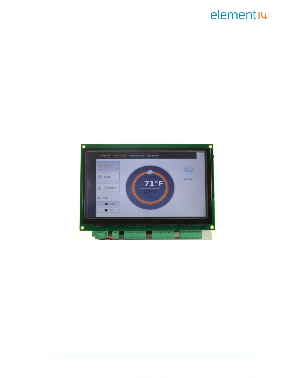
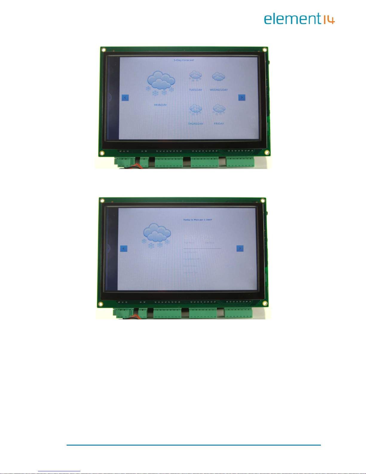
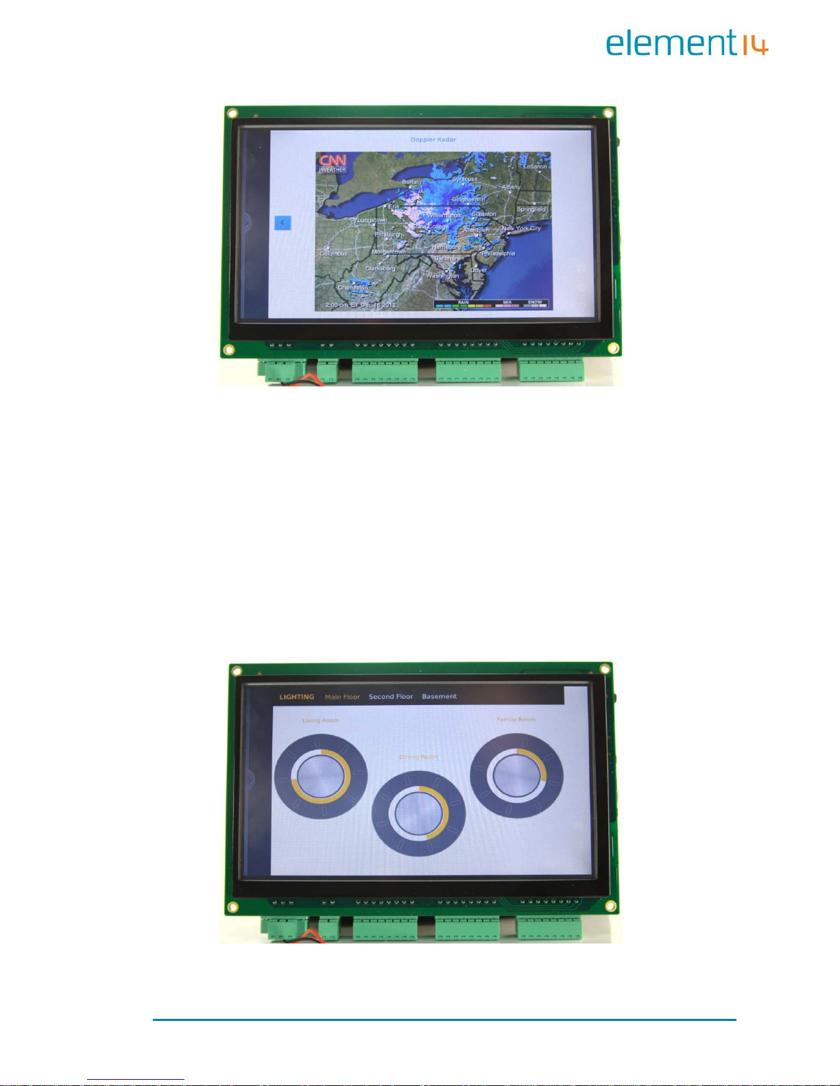
4.1.1.1 Climate Control
This ap plication allo ws the user to control the tem perature an d humidity
throughout the house on a room by room basis. There is also a display
indicating the current weather which can be activated to display extra
information:
Page 23
Page | 18
5 day forecast
Detailed current weather inf o rmation
Page 24
Page | 19
Pulse-doppler radar weather display
The weather information is updated via the internet and as such the
EDM6070 requires an internet connection in order to provide this
functionality
4.1.1.2 Lighting Control
Page 25
Page | 20
The ligh tin g a p plicatio n a llo w s th e us er to set th e l ig h t levels in ea c h r o om
independently. The application emulates a standard dimmer switch making
the software both intuitive and user friendly
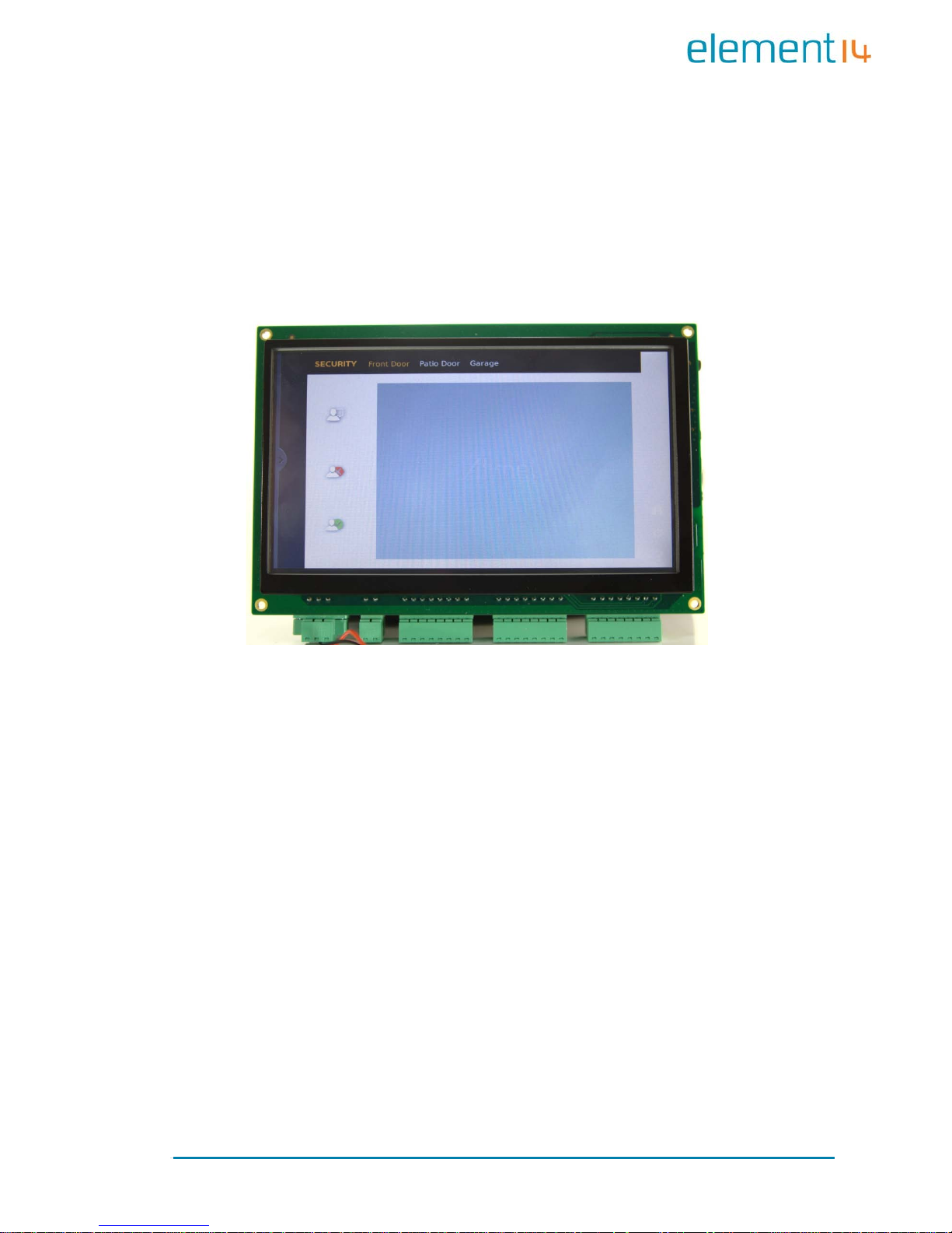
4.1.1.3 Security
The security applicati on allows the EDM6 070 to connect to cameras and door
locks at any user defined entrance. This allows the user to monitor the
entrance and either allow or deny access to the p ro perty
Page 26

Page | 21
4.1.1.4 Media Pl ayer
The Media application will allow the user to play audio into any connected
room. The audio files can be streamed from internet radio, terrestrial /
satellite radio or a local media server such as a PC or networked storage.
4.1.2 Programming the demo
Follow th e steps below to program the demo onto the E DM6070
1) Set up a HyperTerminal as shown in 4.2 System Setup.
2) Copy the demo files from:
\02 Linux 2.6 kit\00 image\
on the CD to the root directory of a MicroSD card
Figure 8: Demo Fi les
Page 27

Page | 22
3) Enable NAND Flash and disable Seri al Flash according to the switch
settings shown below: (refer to
Figure 2: MINI6935 CPU Module
(Front View) for the switch location)
Figure 9: Switch Settings 1
4) Inse rt a MicroS D card in to the MicroS D slot of the board, then power
it up. The booting information in the HyperT erminal window is shown
below:
RomBOOT
Start AT91Boot strap...
Init DDR... Done!
Downloading im age...
*** f_ope n, File name: [logo]: error!
When you hear a beep and see the information below, the programming has
completed.
NAND writ e: dev ic e 0 of fset 0x0, si ze 0x260000
[nand_write_s kip_bad] return rval
2490 36 8 bytes writ ten: OK
NAND erase: devic e 0 offset 0xc 00000, siz e 0x6e00000
Erasing at 0x79e0 000 -- 100% complete.
OK
NAND write: devic e 0 offset 0xc 00000, siz e 0x5540000
89391104 bytes written: OK
5) Turn OFF the board and enable NAND Flash using the switch settings
shown below:
Figure 10: Switch Settings 2
Page 28

Page | 23
6) Turn the board on again and wait a few moments. Th e smart home
demo UI s hould be displayed o n the scre en
4.2 System Setup
Prior to commencing various features tests for EDM6070, yo u shou ld fir st
configu re a Hy pe rTerminal acc or di ng t o th e param et ers sho wn i n t he fi gure
below;
Figure 11: Config uring Hyp erTer mi na l
After setting up the HyperT erminal, connect EDM6070 to your PC via a serial
interface adapter and a serial cable, and t hen power on the board. You can
see boot-up information in the HyperTerminal window.
Page 29

Page | 24
4.3 Testing Features
Note:
Each instruction has been proceeded by a pencil “” to prevent confusion
caused b y any long instruc tions that occ up y m o re tha n one li ne in the co nt e xt.
Please note that there are SPACES in some of th e followi ng instruc tions; Miss ing
any SPACE will lead to failure when running an application.
4.3.1 Touchscreen Test
7) Execute the following instruction to run the touch screen calibration
program;
[root@Min i69X5:/] # ts_calibrate
And then press the “+” symbols that appear on the screen with your
fingers or a compatible stylus to complete calibration;
8) Execute the following instruction to test the touchscreen;
[root@Min i69X5:/] # ts_test
Select Drag or Draw on the screen to test the dragging an d drawi ng
functionalities.
You can exit the example application by pressing Ctrl+C on your PC’s
keyboard.
4.3.2 LCD Colour Test
Upon execution of the following instruction the LCD will display the 3
elementary RGB colours separately and together.
[root@Mini69X5:/]# /home/app/lcd
Page 30

Page | 25
4.3.3 LCD Backlight Test
1) Execute the following instruction to adjust the backlight. The
brightness value can be any integer from 1 t o 10 in clus ive. In t hi s
example the brightness has been set to 5
[root@Min i69X5:/] # bl_adjust SET 5
2) Execute the following instruction to turn off the backlight;
[root@Min i69X5:/] # bl_adjust OFF
3) Execute the following instruction to turn on the backlight;
[root@Min i69X5:/] # bl_adjust ON
4.3.4 Ethernet Test
1) Execute the following instruction to set the IP address of the
EDM6070 to 192.192.192.200;
[root@Min i69X5:/] # ifconfig eth0 192. 192.192. 200
2) Execute the following instruction to test network connection;
[root@Min i69X5:/] # ping 192.192.192 .105
3) Execute the following instruction to set the gateway addres s;
[root@Mini69X5:/]# ro ut e ad d de fault gw <Yo ur_GateWa y_Addr>
For example:
[root@Mini69X5:/]#route add default gw 192.192.192.101
4) Execute the following instruction to set DNS address;
[root@Mini 69X5:/]# echo “nameserver <Your_DNS_Addr>” >
/etc/resolv.conf
For example:
[root@Mini69X5:/]# echo "nameserver
202.96.128.166" >/etc/resolv.conf
Page 31

Page | 26
Note:
The IP addresses above are only examples. Make su re the I P addre ss of the
EDM6070 is in the same network range as your PC.
After all the sett ings are complete, execute a PING command to test the
network connection. The HyperTerminal window will show similar
information to that which follows:
PING 192. 19 2. 19 2. 105 (192.1 92.192.105): 56 da ta bytes
64 bytes from 192.192.192.105: icmp_seq=0 ttl=64 time=0.5 ms
64 bytes from 192.192.192.105: icmp_seq=1 ttl=64 time=0.3 ms
64 bytes from 192.192.192.105: icmp_seq=2 ttl=64 time=0.3 ms
64 bytes from 192.192.192.105: icmp_seq=3 ttl=64 time=0.3 ms
--- 192.192.192.105 ping statistics --7 packets tra ns mi tt ed, 7 packet s received, 0% packet loss
round-tri p min/avg/ max = 0.3/0.3/0.5 ms
~ $
To terminate the Ethernet test, press Ctrl+C on your keyboard.
4.3.5 Serial Interface (RS232) Test
EDM6070 provides 3 serial interfa ces - ttyS2(RS232), ttyS0(RS485)
and ttyS6 ( RS232 ) as debugging interfaces. Execute the following
instruction to test these serial interfaces.
[root@Min i69X5:/h ome/app]# ./com -d /dev/ttyS2 -s 1234567890 -b
115200
Table 1: Parame ters Used in Ins tr uctio ns
Parameters Descriptions
-d Serial device node used to specify a serial interface
-s Character string to be sent
-b Set bitrate
-f Enable hardware flow control
Page 32

Page | 27
4.3.6 CAN Bus Test
Connect your EDM6070 to ano ther EDM6070 or a device with a CA N bus
according to the figure shown below;
Figure 12: CAN Bus Connection
Note:
The jumper JP13 in the figure shown above is shorted in order to enable 120R
terminal resistor.
After connection is complete, execute the f ollowing instructions to test the
CAN bus;
[root@Min i69X5:/] # cd /home/app/can /
[root@Min i69X5:/] # ifconfig can0 down
[root@Min i69X5:/] # ip link set can0 type ca n bitrate 800 000 (Set
bitrate to 800k
)
[root@Min i69X5:/] # ip -detail s li nk show can0 (View can0
configurations)
[root@Min i69X5:/] # ifconfig can0 up (Enable can0)
[root@Mini69X5: /ho me/app/c an/]# ./ca ndump can0 (Receiving mode)
[root@Mini69X5: /home/app/can/]# ./cansend can0
"5A1#1122334455667788" (Sen d st an da rd frames)
[root@Min i69X5: /ho me/app/can/]# ./ cansend ca n0
"1F334455#1122334455667788" (Send ext en de d fr ames)
To terminate the CAN bus test, press Ctrl+C on your keyboard.
Page 33

Page | 28
4.3.7 RS485 Bus Test
The device corresponding to RS485 interface is /dev/ttyS0. Similar to the
CAN bus test, the transceiving test over this bus needs another EDM6070 or
RS485-enabled device; connect them according to the figure shown below;
Figure 13: R S485 Bus Con nection
Note:
For long-distance transmission, the jumper JP12 needs to be shorted.
Execute the following instruction to test the RS485 bus connection;
[root@Min i69X5: /ho me/app/]# ./com -d /dev/ttyS0
To terminate the RS485 bus test, press Ctrl+C on your keyboard.
Page 34

Page | 29
4.3.8 USB Test
EDM6070 has a USB host interface. Upon inserting an USB flash drive into
the EDM6070 USB port the HyperTerminal window will show informatio n as
follows;
usb 1-1: US B disconne ct, address 2
usb 1-
1: new fu ll speed USB device us ing at91_ohci and address
3
usb 1-1: configuration #1 chosen from 1 choice
scsi2 : SCS I em ul at io n for USB Mass Storage devices
scsi 2:0 :0:0 : Dire ct-Access Generic USB SD Reader 0.00
PQ: 0 AN SI: 2
sd 2:0:0:0: [sda] 7744512 512-byte hardware sectors (3965 MB)
sd 2:0 :0:0: [sda] Write Protect is off
sd 2:0:0:0: [sda] Assuming drive cache: write through
sd 2:0:0:0: [sda] 7744512 512-byte hardware sectors (3965 MB)
sd 2:0 :0:0: [sda] Write Protect is off
sd 2:0:0:0: [sda] Assuming drive cache: write through
sda: sda1
sd 2:0 :0:0: [sda] Attached SCSI removable disk
sd 2:0 :0:0: Attached scsi generic sg1 type 0
The above information indicates that the USB flash drive has been identified
as sda1 device by the system. Follow the steps listed belo w to imp lemen t
the test;
1) Execute the following instruction to mount the USB flash drive to
/mnt and s pecify the format as VFAT;
mount –t vfat /dev/sda1 /mnt
Note:
By defa ult, US B fla sh dri ve is m o u nted auto m atica ll y to /media under the root
file system. If automatic mounting fails, you need to mount the device manually
by using the above i ns tru ct ions.
Page 35

Page | 30
2) Execute the following instruction to view the contents of the USB
flash drive;
root@Mini69X5:/mnt/usbhd-sda1]# ls
3) Execute the following instructions to un-mount the USB flash drive;
[root@Mini69X5:/mnt/usbhd-sda1]# cd ..
[root@Mini69X5:/mnt]# umount usbhd-sda1
4.3.9 RTC Test
RTC is used to store and recover the system clock. Follow the s teps listed
below to test the RTC;
1) Execute the following instruction to view the current system clock;
[root@ Mini 69X5:/]# date
The system clock readout is shown below;
Thu Nov 27 11:48:02 UTC 2013
2) Execute the following instructions to set system clock to 16:43, Nov .
29
th
, 2013;
[root@Mini69X5:/]# date –s 112916 432013
The HyperTerminal shows i nformation as follows;
Thu No v 29 16:43:00 UTC 2013
3) Execute the following instruction to write system clock into RTC;
[root@ Mini 69X5:/]# hwclock –w
4) Execute the following instruction to view RTC clock;
[root@ Mini 69X5:/]# hwclock -r
The HyperTerminal shows i nformation as follows;
Thu No v 29 16:43:00 UTC 2013
Page 36

Page | 31
5) Execute the following instructions to update system clock with the
clock information stored in RTC, and them view the system clock;
[root@ Mini 69X5:/]# hwclock -s
[root@ Mini 69X5:/]# date
The updated system clock is shown below;
Thu No v 29 16:43:45 UTC 2013
Note:
RTC can work properly as long as there is always a battery supplying power;
Ensure an R1220 battery is installed.
4.3.10 TF Card Test
Insert a microSD card into the microSD card slot of EDM6070, the
HyperTerminal sho ws information as follows;
[root @Mini69X5:/]# mmc1: new SD card at address 0002
mmcblk0 : mm c1:0002 N/A 489 MB
mmcblk0 : p1
The above information indicates that card has been de fined as mmcblk0p1
device. Follow the steps listed below to implement the test;
1) Execute the following instruction to mount the card to /mnt and
specify the format as VFAT;
[root@Min i69X5:/] # mount -t vfa t /d ev/mmcbl k0p1 /mnt/
2) Execute the following instructions to view the contents of the card;
[root@Min i69X5:/] # cd /mnt/
[root@Mini 69X5:/mnt]# ls
3) Execute the following instructions to un-mount the card;
root@Mini 69X5:/mn t]# cd /
[root@Min i69X5:/] # umount /mnt/
Page 37

Page | 32
4.3.11 LED Test
EDM6070 has 2 LED i ndicators, among the m the D 2 is a system status LED .
The following steps are the test for D1 (PB18) LED;
1) Execute the following instruction to test LED D1 by running an
application;
[root@Min i69X5:/] # /home/app/led
D1 will be blinkin g alternately at two differe nt frequencies ;
2) Execute the following instruction to turn OFF a single LED;
[root@Mini69X5:/]# echo '0' >/sys/class/leds/d1/brightness
3) Execute the following instruction to turn ON a single LED;
[root@Mini69X5:/]# echo '1' >/sys/class/leds/d1/brightness
4.3.12 Buzzer Test
1) Test by running an application;
[root@Min i69X5:/] # /home/app/beep
The buzzer will make a single sound;
2) Instruct the buzzer to make continues sound;
[root@Mini69X5:/]# echo '1' >/sys/class/leds/beep/brightness
3) Instruct the buzzer to stop making sound;
[root@Mini69X5:/]# echo '0' >/sys/class/leds/beep/brightness
4.3.13 GPIO Test
The GPIO test program constantly reads the input interface at a 500ms
interval and control the data receiving on output interface. Execute the
following instruction to implement the test;
Page 38

Page | 33
[root@Min i69X5:/] # /home/app/gpio
If the test is successful, the HyperTerminal window shows information as
follows;
---------------------------------------
* MINI69X5 GPIO Demo *
--------------------------------------GPIO_PB15 INPUT 1
GPIO_PD16 INPUT 1
GPIO_PD17 INPUT 1
GPIO_PD 18 OUT PU T 0
GPIO_PD 18 OUT PU T 0
GPIO_PD 18 OUT PU T 0
GPIO_PD 18 OUT PU T 0
4.3.14 Button Test
Execute the following instruction to test the button SW1 on the EDM6070;
[root@Min i69X5:/] # /home/app/evte st /dev/ev ent0
The HyperTerminal window shows in formation as fol lows;
Inpu t drive r ev dev: (EVI OCGBIT ): S uspi ciou s buff er si ze
511, limiting output to
64 bytes. See
http://userweb.kernel.org/~dtor/eviocgbit-bug.html
version is 1. 0. 0
Input dev ice ID: bu s 0x19 ve ndor 0x 1 prod uct 0x1 ver sion
0x100
Input dev ic e na me : "g pio-keys"
Supported events:
Event typ e 0 (S yn c)
Event type 1 (Key)
Event code 278 (BackBtn)
Press SW1, the HyperTerminal window shows informat ion as follows;
Page 39

Page | 34
Event: time 1167614678.630509, type 1 (Key), code 278
(BackBt n) , va lu e 1
Event: time 1167614678.630529, -------------- Report Sync
-----------Event: time 1167614678.826399, ty
pe 1 (Key), code 278
(BackBt n) , va lu e 0
Event: time 1167614678.826412, -------------- Report Sync
-----------Event: time 1167614679.430801, type 1 (Key), code 278
(BackBt n) , va lu e 1
Event: time 1167614679.430817, -------------- Report Sync
-----------Event: time 1167614679.668320, type 1 (Key), code 278
(BackBt n) , va lu e 0
To terminate the button test, press Ctrl+C on your keyboard.
4.3.15 Screen Capture Test
Execute the following instruction to capture the contents displayed on the
LCD and save it as a jpg image;
[root@Min i69X5:/] # fbcat /dev/fb0 Fig ure.jpg
The captured images will be saved automatically under the system’s root
directory.
4.3.16 Audio Test
The system contains an open-source audio player “madplay” by default
which supports MP3 playback. Insert headphones into the 3.5mm audio
output jack on EDM6070, and then execute the following instruction to
implement a test;
[root@Min i69X5:/] # madplay /home/mp 3/music. mp3
If you hear music, the audio functionality is working properly .
To view help information, execute instruction “madplay
–h”.
Page 40

Page | 35
4.3.17 Watchdog Test
Execute the following instruction to run the watchdog tes t program;
[root@Min i69X5:/] # /home/app/watc hdog
The HyperTerminal window shows information as follows;
Watchdo g op en suc ce ss
usage:
[a ] -- Feed dog
[q ] -- Quit without stop watchdog
[e ] -- Quit and stop watchdog
4.3.18 Telnet Test
Connect EDM6070 to your LAN by using a RJ45 network ca ble, and then
follow the steps listed below to implement the test;
1) Open a command prompt, the method for doing this can vary
depending on your version of windows.
Note:
For Windows X P: click start, then run and in the dialogue box that appears
type “cmd” and hit enter on your keyboard.
For Windows 7: c lick s tart t hen e nter “c md” int o the s earc h box then hit e nter
on your keyboa rd.
You will then be presented with a window as follows.
Page 41

Page | 36
Figure 14: Command Prompt Window
2) Type “p ing 192.192. 192 .2 11” to test the network connection (the
default IP address of the EDM6070 is 192.192.192.211) as shown
below;
Figure 15: Network Test After Completion
3) Type “telnet 192.192.192.211” to initiate a telnet session as
shown below;
Page 42

Page | 37
Figure 16: T e l ne t Se s s ion Initializa tion
4) Type the default username “root” and leave the password blank as
shown below;
Figure 17: Telnet Log In
Now you have logged in to the telne t session successfully , to exit the session,
type “exit”.
Note:
By default, telnet service is disabled under Windows 7. To enable th e serv ice
select Control Panel > Programs > Programs and Features > Turn Windows
features on or off, and then check “Telnet Client”.
The default IP address o f EDM6070 is 192.1 92. 192. 211. Ensure t ha t the boar d
and your PC are set in the same network segment.
Page 43

Page | 38
4.3.19 Mounting NFS (Network File System)
By mounting the NFS (Network File System), users can access the shared
directory remotely under a Linux environment. Follow the steps listed below
to test the NFS netwo rk file system;
1) Log in to the Linux system on your PC as a root user;
2) Add the following line at the end of the file /etc/exports, and then
save the changes;
/home/nfs *(rw,sync,no_root_squash)
/home/nfs: Shared directory on NFS server; mountable by all
client ter m inals
no_root_squash:Allow the client terminals which mount the
directory to operate as a root user;
3) Execute the following instruction to enable the NFS server;
[root@:/] # /etc/ini t.d/nfs-kernel-server start
4) Check if the NFS server is enabled successfully;
[root@:/] # mount -o nolock localhost:/home/nfs /tmp
If th ere is no error repo rte d by sy stem and th e i nformati on obt ai ned
by executing “ls /tmp” is consistent with the contents under the
shared di rectory o f the NFS server , the server is functioning properly.
5) Power on ED M607 0 and conne ct i t to a PC wi th a n etwork ca ble , and
then set the IP address for the board in the HyperTerminal window;
Make sure the communication between the board and your PC’s
Linux system is working properly by executing a PING command;
Page 44

Page | 39
6) Execute the following instruction in the HyperTerminal window to
mount the shared directory /home/nfs to /mnt
[root@Min i69X5:/] # mount -o nolock 192.192.192.105:/home/nfs /mnt
After mounting successfully, you can see the contents of the shared
directory under /mnt.
Note:
EDM6070 has write permission to the shared directory, and therefore any
changes will be sa ved.
4.4 Transferring Files Using SecureCRT
Follow the steps listed below to test data trans fer via serial interfaces by
using Windows-based sof tware SecureCRT;
1) Open a SecureCRT software window as shown below;
Figure 18: SecureCRT Wind o w
Execute the following instructions in the window;
[root@Min i69X5:/] # cd /tmp
[root@Min i69X5:/t mp]# rx recvfile
2) Click Transfer > Send XModem on the menu bar to open the
following window;
Page 45

Page | 40
Figure 19: File Selection
Select a file to be sent and then click send; The HyperTerminal
window shows inf ormatio n as follows;
Starting xmodem transfer. Press Ctrl+C to cancel.
Transferring dataflash_at91sam9g45ekes.bin...
100% 4 KB 0 KB/s 00:00:05 0 Errors
[root@Mini69X5:/tmp]#
The above information indicates that the file has been received
successfully.
Note:
Seria l inte rfac es wo rk at a rela tive ly lo w spe ed, s o it is reco mme nded to choose
a sm all fi le when tra n sferring.
4.5 Transferring Files Using Network Protocol
Follow the steps listed below to transfer a large file using the TFTP protocol;
Page 46

Page | 41
1) Put the file to be sent in the HOME directory (e.g. G:\data.bin) and
run tftpd.exe (this program can be found under “\02 Linux2.6
Kit\02 Tools\” in the CD-ROM) on your PC; Select Tftp >
Configure on the menu bar of the program window, and set the
path to Home Directory, and then select Tftp > Start on the menu
bar to start TFTP service;
2) Execute the following instruction in the HyperTerminal window to
download data.bin file;
[root@Mini69X5:/tm p]# tftp -g 192.192. 192.71 -r data.bin
3) Execute the following instruction to view the downloaded file;
[root@Mini69X5:/tmp]# ls -l
The Hype rTerminal window shows information a s follows;
-rw-r--r-- 1 root root 4420 Jan 1 00:44 data.bin
The above information indicates that the file has been
downloaded successfully.
4) Execute the following instruction to rename the downloaded file as
data_send.bin;
[root@Mini69X5:/tmp]# mv data.bin data_send.bin
5) Execute the following instruction to upload the file to the HOME
directory of your PC;
[root@Mini69X5:/tmp]# tftp -p 192.192.192. 71 -l data_send.bin
6) Enter the shared directory to view the uploaded file as shown below;
Page 47

Page | 42
Figure 20: Uploaded File
The image shown above indicates a successful uploading.
4.6 Linux QT Demonstration
When the system is under the shell interactive mode, you can start the
Qtopia applic ation b y enter ing the c omm and “qpe”. Then follow t he step s
listed below;
1) Execute the following instruction in the HyperTerminal window to
begin calibration of the touch screen;
[root@Min i69X5:/] # ts_calibrate
Follow the instructions as they appear on the screen to
implement calibration;
2) Execute qpe command to run Qtopia applications; (the file system
has to have a QT installed)
[root@Min i69X5:/] # qpe
Page 48

Page | 43
The QT interface and sys tem information are shown belo w;
Figure 21: Mai n QT Interface
Figure 22: Q T In terfa ce Sho wing System Info r ma tio n
Page 49

Page | 44
Chapter 5: Development
Environment and System
Compilation
Before g etting star ted with the deve lopment on the board, an ARM Linux
cross development environment is required. This chapter will take Ubuntu as
the example operating system to show you how to build a cross
development environment and accomplish system compilation.
5.1 Building a Cross Compilation Environment
The CD-ROM provided with the product contains a cross compilation tool
“arm-2007q1-10-arm-none-linux-gnueabi-i686-pc-linux-gnu.tar.bz2”
under the directory “\02 Linux2.6 Kit\02 T ools\”. Install it step by step
as shown below.
1) Put the CD-ROM in your drive. Ubuntu will mount the CD to
/media/CD-ROM by default. Execute the following instructions to
install the cross compilation tool;
mkdir /usr/l ocal/arm
tar –jxvf
arm-2007q1-10-arm-none-linux-gnueabi-i686-pc-linux-gnu.tar.bz2 –C
/usr/local/arm
2) Execute the following instruction to add an environment variable
which specifies the path to the cross compilation tool in the system.
export PATH =/usr/lo cal/arm/arm-2007q1/bin/:$PATH
3) Execute the following instruction to check if the installation is done;
arm-none-linux-gnueabi-gcc –v
Page 50

Page | 45
The Hype rTerminal window shows information a s follows;
Using built-in sp ec s.
Target: arm-none-linux-gnueabi
…
gcc version 4.2.0 20070413 (prerel
ease) (CodeSourcery
Sourcer y G+ + Li te 200 7q1-10)
If the ver sion nu mber within th e last l ine is corr ect, t he cross compila tion
environment has been built successfully.
Note:
The instruction adding environment variables can be put into the file .bashrc
under user directory to allow the system load the variable automatically each
time when it boots up.
5.2 System Compilation
The com pila tion o f the operating system can be accomplished in 5 steps –
uncompressing fil es, making a Bootstrap, making a U-boot, maki ng a kernel
and making a file system image. This section will introduce these steps in
detail.
5.3 Uncompressing Files
The system source code can be found under \02 Linux 2.6 K it\01 Source
Code\ in the CD-ROM. Execu te the fo llo win g instr uct ions to uncompr ess it
under a Linux system.
root@LINUX SERVER:~# mkdir embest
root@LINU XSERVER: ~# cd embest/
root@LINUXSERVER:~/embest# cp /media/cdrom/02\ Linux\ 2.6\ Kit/01\
SourceCode/bootloader/ AT91Bootstrap-5series_1.2. tar.bz2 ./
root@LINUXSERVER:~/embest# cp /media/cdrom/02\ Linux\ 2.6\ Kit/01\
Page 51

Page | 46
SourceCode/bootloader/ u-boot-a t9 1sam9x35 .tar.bz2 ./
root@LINUXSERVER:~/embest# cp /media/02\ Linux\ 2.6\ Kit/01\ Source
Code/kernel / li nux-2.6.39. ta r. bz 2 ./
root@LINUXSERVER:~/embest# cp /media/cdrom/02\ Linux\ 2.6\ Kit/01\
SourceCode/rfs/ rootfs.tar.bz2 ./
root@LINU XSERVER: ~/embest# tar jxvf /media/cdrom/02\ Linux\ 2.6\
Kit/02\ Tools/mkubifstools.tar.bz2 –C /usr/local/bin/
root@LINUXSERVER:~/embest# cp /media/cdrom/02\ Linux\ 2.6\ Kit/02\
Tool s/mkimage /usr/local/bin/
root@LINUXSERVER:~/embest# chmod 755 /u sr/local/bin/mk yaffs2im age
/usr/local/bin/mkimage
root@LINU XSERVER: ~/embest# tar jxvf
AT91Bootstrap-5series_1.2.tar.bz2
root@LINU XSERVER: ~/embest# tar jxvf u-boot-at91sam9x35.tar.bz2
root@LINU XSERVER: ~/embest# tar jxvf linux-2.6.39.tar.bz2
root@LINUXSERVER:~/embest# mkdir rfs; tar jxvf rootfs.tar.bz2 -C rfs
Four directories - linux-2.6.39, u-boot-1.3.4, Bootstrap-v1.14 and
rfs-qtopia have been generated under the current dire ctory.
5.4 Making a Bootstrap
EDM6070 supports boot-up from DataFlash. Execute the following
instruction to generate a Bootstrap;
root@LINU XSERVER: ~/embest# cd AT91B ootstrap -5series_1.2
root@LINU XSERVER: ~/embest/ AT91Bo otstrap-5series _1 .2 # ma ke
sam9x35_defconfig; cp sam9x35_defconfig .config
root@LINUXSERVER:~/embest/ AT91Bootstrap-5series_1.2 # make
A Bootstrap file at91sam9x5ek-dataflashcardboot-3.1.bin has been
generated under directory “binaries”.
Page 52

Page | 47
5.5 Making a U-boot
Execute the following instructions to generate a u-boot;
root@LINUXSERVER:~/embest/ u-boot-at91# make
at91sam9x5ek_spiflash_config
root@LINU XSERVER: ~/embest/ u-boot-at91# ma ke
A file U-boot.bin has been generated under current directory.
Note:
An error might occur when using
arm-2007q1-10-arm-none-linux-gnueabi-i686-pc-linux-gnu.tar.bz2 to compile
u-boot; the use of
arm-2011.03-41-arm-none-linux-gnueabi-i686-pc-linux-gnu.tar.bz2 is
recommended when encountering any errors.
5.6 Making a Kernel
Execute the following instructions;
root@LINUXSERVER:~/embest/linux-2.6.39# make
at91sam9x5ek_defconfig
root@LINUXSERVER:~/embest/linux-2.6.39# make menuconfig
root@LINUXSERVER:~/embest/linux-2.6.39# make uImage
A kernel file named uImage has been generated under /arch/arm/boot/.
Note:
If errors oc cur w hen exec uting “make menuconfig”, the most likely cause is t he
lack o f an ncurses library in your PC’s Linux system.
Execute “sudo apt-ge t i ns tall libncurses5-dev” to install the library.
Page 53

Page | 48
5.7 Making a File system Image
Use the tool mkyaffs2image under the directory \02 Linux 2.6 Kit\02
Tools\ of the CD-ROM to make a file system image by executing the
following instruction (suitable for Ubuntu systems only).
root@LINUXSERVER:~/embest# mkubifsimage rfs rootfs.ubifs
Page 54

Page | 49
Chapter 6: System Customization
In order to satisfy different application requirements of the customers,
designers need to make some customisation to the default configuration of
the Linux kernel. This chapter will introduce the process of system
customization by using some examples.
6.1 Kernel Customisation
By default, the kernel source code provides a configuration file saved under
arch/arm/configs/at91sam9x5ek_defconfig. Execute the following
instructions to enter the configuration menu and then select the drivers you
need according to the entries shown in the table below:
root@LINUXSERVER:~/embest/linux-2.6.39# make
at91sam9x5ek_defconfig
root@LINUXSERVER:~/embest/linux-2.6.39# make menuconfig
Page 55

Page | 50
Drivers Paths
Serial
Interfaces
Device drivers > Character devices > Serial drivers > AT91 / AT32
on-chip serial po rt su pp o rt
Buttons Device drivers > Input device support > Keyboards > GPIO Buttons
GPIO Device driv e rs > Mi sc devices > Devic e driver for Atm e l GPIO de vices
LED
Device drivers > LED Support > LED Class Support > LED Support for
GPIO connecte d LEDs
SD/MMC
Device drivers > MMC/SD/SDIO card suppo
rt > MMC block device
driver > Atmel SD/MMC Driver (Atmel Multimedia Card Interface
support)
USB
Device drivers > USB support > Support for Host-side USB > EHCI HCD
(USB 2.0) s upport > OHCI H CD support > USB M ass Stor age supportH CD
support > USB Mass Stora ge su ppor t
RTC Device drivers > Real Time Clock > AT91RM9200 or some AT91SAM9 RTC
Watchdog Device drivers > Watchdog Timer Support > AT91SAM9 watchdog
CAN Bus
Networking support > CAN bus subsystem support > CAN Device
Drivers > Atmel AT91 onchip CAN controller
MACB
Device drivers > Network device support > Ethernet(10 or 100Mbit) >
Atmel MACB su pp or t
Graphics
Device driv er s > Gr aphi cs su pp ort > Sup port f or f r ame buf fer d evi c es >
AT91/AT3 2 LCD Controller support
Page 56

Page | 51
Drivers Paths
Touch-Screen I n put device support > Touchscreens > Atmel Touchscreen Interface
Save the changes and execute the instruction below to compile the
customized kernel;
root@LINUXSERVER:~/embest/linux-2.6.24# make uImage
6.2 File system Customisation
The table shown below lists the configuration files required for filesystem
customisation, applications’ paths and corre s po nding notes;
Configuration List Paths Notes
Driver Modules /lib/modules/2.6.39/
Store driver module
ko
Driver Module Mounting /etc/init.d/S50modules
Network Address /etc/network/interfaces.eth0
Command Li ne Prompt Name /etc/hostname
User Program Auto Running /etc/init.d/S60evnset Add it to the end of file
Environment Variables /etc/profile
Touch-Screen Coordinate Files /etc/pointercal
udev Rules /etc/udev
Page 57

Page | 52
LCD Backlight Brightness /etc/bl_adjust.conf
User Testing Applications /home/app
6.3 Simple Driver Modules in Kernel
Drivers are running under kernel mode and can drive hardware directly.
They provide a series of interfaces to be called by applications so as to
control devices. The table shown below is an example of driver modules that
are simple but include most of the interfaces.
/* File: device_drv.c */
#include <linux/kernel.h>
#include <linux/module.h>
#include <linux/init.h>
#include <linux/input.h>
#include <linux/miscdevice.h>
#include <asm/io.h>
#include <asm/uaccess.h> /* common head files used by driver */
#define DEVICE_NAME "demo" /* device names that generate nodes /dev/demo
after mounting successfully */
static int result = 0;
static int device_open(struct inode *inode, struct file *file) /*
implement open operation */
{
result = 0; /* initiate result */
return 0;
}
static ssize_t device_read(struct file *filp, char *buffer, size_t count, loff_t
Page 58

Page | 53
*ppos) /* implement read operation */
{
int ret = copy_to_user (buffer, (char *)&result, sizeof(result)); /*
copy the value of result to buffer */
if (ret < 0) {
printk (KERN_ERR "%s: copy_to_user error\n", DEVICE_NAME);
return -1;
}
return sizeof(result);
/* return the valid length of
buffer, i.e. the storage length of result */
}
static ssize_t device_write(struct file *filp, const char *buffer, size_t count,
loff_t *ppos) /* write operation*/
{
int ret = copy_from_user ((char *)&result, buffer, sizeof(result));
/* copy the received data in buffer to result*/
if (ret < 0) {
printk (KERN_ERR "%s: copy_from_user error\n", DEVICE_NAME);
return -1;
}
return sizeof(result);
}
static int device_release(struct inode *inode, struct file *filp) /*
close will trigger the function */
{
return 0;
}
static struct file_operations device_fops =
/* register interface
function for file operation */
{
.owner = THIS_MODULE,
.open = device_open,
.read = device_read,
.write = device_write,
.release = device_release,
};
static struct miscdevice device_miscdev =
/* register misc
device information */
{
.minor = MISC_DYNAMIC_MINOR,
.name = DEVICE_NAME,
.fops = &device_fops,
};
static int __init device_init(void) /* insmod operation will
Page 59

Page | 54
trigger the function */
{
int ret;
ret = misc_register(&device_miscdev); /*register device */
if (ret) {
printk(KERN_ERR "cannot register miscdev on minor=%d (%d)\
n",
MISC_DYNAMIC_MINOR, ret);
goto out;
}
printk(KERN_INFO DEVICE_NAME " initialized!\n");
return 0;
out:
return ret;
}
static void __exit device_exit(void)
/* rmmod operation will
trigger the function */
{
misc_deregister(&device_miscdev);
printk(KERN_INFO DEVICE_NAME " removed!\n");
}
module_init(device_init);
module_exit(device_exit);
MODULE_LICENSE("GPL");
/* protocol used by
driver modules */
MODULE_DESCRIPTION("Linux Driver Demo");
/* driver module
description */
Page 60

Page | 55
6.4 Using Makefile to Associate Drivers with Kernel
Driver files h ave to be as sociate d with the kernel by a Makefile before they
can be compiled and loaded. The following table shows the source code of
the provided Makefile.
# File : Makefile
ifneq ($(KERNELRELEASE),)
obj-m := device_drv.o # driver fil
e with extension name .o
other than .c; by default .c files will be searched and compiled
automatilly
else
KERNELDIR ?= ~/embest/linux-2.6.39 # specify the path of kernel
source code, not e that the path mus t be the location where you save th e
code
PWD := $(shell pwd)
all:
$(MAKE) -C $(KERNELDIR) M=$(PWD) modules
clean:
rm -
rf *.o *~ core .depend .*.cmd *.ko *.mod.c .tmp_versions
Module. sy mv er s mo dules.or der device_drv.k o
endif
6.5 Compiling and Downloading Drivers
Before you start to compile drivers using “make” command, the kernel
source code should be compiled first. After compiling successfully, you can
download the generated file device_drv.ko to the board, and then execute
the following instructions and see the feedback from the system.
[root@Min i69X5:/] # insmod device_dr v.ko
demo initialized!
[root@Min i69X5:/] # ls /dev/demo
/dev/demo
[root@Min i69X5:/] # rmmod device_drv .ko
Page 61

Page | 56
demo removed!
6.6 Brief Introduction to Applications
The previous example shows t he execution process of drivers. You might
notice that only two functions – device_init and device_exit have been
called, w hil e ot her s r em a in u nus ed in the a b o ve p r ocess . The interfac es in
structure device_fops are intended for the application layer. The table
shown below will give you an example of the basic structure of a Linux
application.
/* File: demo.c */
#include <stdio.h>
#include <fcntl.h>
#include <string.h> /* head file being called */
#define dev "/dev/demo" /* demo file node */
int main (void)
{
int fd;
int err = 0;
int value;
fd = open (dev, O_RDWR); /* open file node, readable and writable
*/
if (fd < 0) {
fprintf (stderr, "open fail\n");
err = 1;
goto out;
}
Page 62

Page | 57
if (read (fd, &value, sizeof(value)) < 0) {
/* read function that
calls driver; the read value t is save in value */
fprintf (stderr, "read error\n");
err = 1;
goto out;
}
printf ("read before write, value=%X\n", value); /*
print read value
before writing */
int writeValue = 0x5E7F;
if (write (fd, &writeValue, sizeof(writeValue)) < 0) {
/* writing
0x5E7F to driver module by calling write function */
fprintf (stderr, "write error\n");
err = 1;
goto out;
}
if (read (fd, &value, sizeof(value)) < 0) {
/* read again after
writing */
fprintf (stderr, "read error\n");
err = 1;
goto out;
}
printf ("read after write, value=0x%X\n", value);
/* print read value
after writing */
out:
if (fd > 0) close (fd);
return err;
}
6.7 Compiling and Running Applications
1) Execute the following instruction to compile the application;
# arm-none-linux-gnueabi-gcc demo.c -o demo
Page 63

Page | 58
The generated execut able file named demo is the a pplication w e
need;
2) Execute the following instruction to download it to the board;
[root@Min i69X5:/] # insmod device_dr v.ko
System feedback is shown below;
demo initialized!
3) Execute the following instruction to run the a p p lic a t ion ;
[root@Min i69X5:/] # ./demo
Running information is shown below;
read before write, value=0
read after write, value=0x5E7F
6.8 Common Functio ns
The following three functions are commonly used by the driver layer to
control the GPIO;
Functions Notes
int at91_set_gpio_input(unsigned pin, int
use_pullup)
set GPIO as input
int at91_ ge t_ gp io _value(u nsigned pin)
acquire GPIO input
value
int at91_set_gpio_output(unsigned pin,
int va lue)
set GPIO as output
Adding the above GPIO code to the appropriate location in the drivers as
shown in the following table, can easily implement LED control;
Page 64

Page | 59
Example functions Notes
at91 _set_gpio_input (AT91_PIN_PC16,
0);
set PC16 as input, pull-up
disabled
at91_get_gpio_value
(AT91_PIN_PC16);
read the input value on PC16
at91_set_gpio_output(AT91_PIN_PC16,
1);
set PC 16 to provide high-level
output
6.9 Linux Multi-Thread Pro g ramming
The threads here refer to the multiple tasks created in the user space. These
tasks share resources of the same process. It consu mes much less cost than
common process and feature s f ast cont ext switching.
Since the resources are shared by processes, it is necessary to adopt
synchronizing measures in order to avoid competition when accessing
resources.
r/* File: pthread.c */
#include <stdio.h>
#include <unistd.h>
#include <pthread.h>
void read_func(void);
void write_func(void);
int buffer_has_item = 0; /* shared resource */
pthread_mutex_t mutex; /* mutex lock */
Page 65

Page | 60
int main(void)
{
pthread_t reader, writer; /* define process ID
*/
pthread_mutex_init(&mutex, NULL);
/* initiate mutex
lock */
pthread_create(&reader, NULL, (void*)&read_func, NULL);
/* create
process */
pthread_create(&writer, NULL, (void*)&write_func, NULL);
pthread_join(reader, NULL);
/* wait for end of
process */
pthread_join(writer, NULL);
return 0;
}
void write_func(void)
{
while (1) {
pthread_mutex_lock(&mutex); /* enable lock, other
processes will be locked */
if (buffer_has_item == 0) {
printf("create a new item\n");
buffer_has_item = 1;
}
pthread_mutex_unlock(&mutex);
/* disable lock,
other process will be unlocked */
}
}
void read_func(void)
{
while (1) {
pthread_mutex_lock(&mutex);
if (buffer_has_item == 1) {
Page 66

Page | 61
printf ("destroy item\n");
buffer_has_item = 0;
}
pthread_mutex_unlock(&mutex);
}
}
Execute the following instruction to implement the compilation.
# arm-none-linux-gnueabi-gcc pthread.c -o pthread_demo -lpthread
6.10 Linux Network Programming
Linux network programming generally can be implemented based on UDP
and TCP protocols. UD P is a conne ctionl ess t ranspo rt protocol that provi des
simple, unreliable and message-oriented services; TCP is a reliable,
connection-oriented and byte-stream-based transport protocol. The
follo wing examples are a simple TCP server and a client.
Server: monitors the connection initiated by the client and sends
character stri ng to the client when a connection is created.
/* File: server.c */
#include <stdio.h>
#include <stdlib.h>
#include <errno.h>
#include <string.h>
#include <sys/types.h>
#include <netinet/in.h>
#include <sys/socket.h>
#include <sys/wait.h>
#define MYPORT 3490 /* the port users will be connecting to */
#define BACKLOG 10 /* how many pending connections queue will hold */
main()
{
int sockfd, new_fd; /* listen on sock_fd, new connection on new_fd */
struct sockaddr_in my_addr; /* local address information */
Page 67

Page | 62
struct sockaddr_in their_addr; /* connector's address information */
int sin_size;
if ((sockfd = socket(AF_INET, SOCK_STREAM, 0)) == -1) {
perror (" socket ") ;
exit(1) ;
}
my_addr.sin_family = AF_INET;
my_addr.sin_port = htons(MYPORT);
my_addr. sin_addr.s_addr = INADDR_ANY; /* auto-fill with local IP */
if (bind(sockfd, (struct sockaddr *)&my_addr, sizeof(struct sockaddr)) == -
1)
{
perror (" bind ") ;
exit(1) ;
}
if (listen(sockfd, BACKLOG) == -1) {
perror (" listen ") ;
exit(1) ;
}
while(1) { /* main accept() loop */
sin_size = sizeof(struct sockaddr_in);
if ((new_fd = accept(sockfd, (struct sockaddr *)&their_addr,
&sin_size)) == -1) {
perror (" accept ") ;
continue ;
}
printf("server: got connection from %s\n",
inet_ntoa(their_addr.sin_addr));
if (!fork()) { /* this is the child process */
if (send(new_fd, "Hello, world!\n", 14, 0) == -1)
perror( " send " ) ;
close( new_fd ) ;
exit ( 0 ) ;
}
close(new_fd);
Page 68

Page | 63
while(waitpid(-1,NULL,WNOHANG) > 0); /* clean up child processes */
}
}
Client: Ini tiates a connection to the server, receives and prints
information sent from the server.
/* File: client.c */
#include <stdio.h>
#include <stdlib.h>
#include <errno.h>
#include <string.h>
#include <netdb.h>
#include <sys/types.h>
#include <netinet/in.h>
#include <sys/socket.h>
#define PORT 3490 /* the port client will be connecting to */
#define MAXDATASIZE 100 /* max number of bytes we can get at once */
int main(int argc, char *argv[])
{
int sockfd, numbytes;
char buf[MAXDATASIZE] ;
struct hostent *he;
struct sockaddr_in their_addr; /* connector's address information */
if (argc != 2) {
fprintf(stderr,"usage: client hostname\n");
exit (1) ;
}
if ((he=gethostbyname(argv[1])) == NULL) { /* get the host info */
herror(" gethostbyname ") ;
exit (1);
}
if ((sockfd = socket(AF_INET, SOCK_STREAM, 0)) == -1) {
perror( " socket ");
exit (1);
Page 69

Page | 64
}
their_addr.sin_family = AF_INET;
their_addr.sin_port = htons(PORT);
their_addr.sin_addr = *((struct in_addr *)he->h_addr); //inet_addr
if (connect(sockfd, (struct sockaddr *)&their_addr, sizeof(struct sockaddr))
== -1)
{
perror(" connect ");
exit (1);
}
if ((numbytes=recv(sockfd, buf, MAXDATASIZE, 0)) == -1) {
perror (" recv ");
exit (1);
}
buf[numbytes] = '\0';
printf("Received: %s",buf);
close(sockfd) ;
return 0;
}
6.11 Compiling Server
If you have two EDM6070s, you need to compile a server
program running on one EDM6070 by executing the following
instruction;
# arm-none-linux-gnueabi-gcc server.c -o se rver
If you have only one EDM6070, you need to compile a server
program running on a PC by executing the following instruction;
# gcc server.c -o se rver
6.12 Compiling Client
Execute the following instruction to compile a client program;
Page 70

Page | 65
# arm-none-linux-gnueabi-gcc client.c -o cl ient
6.13 Running Server and Client
In the event that two EDM6070s are to be run in a client/server
pair, download the EDM6070-based se rver and the cli ent programs
to these boards respectively, and then run the server by executing
the following instruction;
# ./server
Run the client by executing the following instructions
(192.192.192.105 is the server IP);
[root@Min i69X5:/] # chmod 755 client
[root@Min i69X5:/] # ./client 192.192 .192.105
The feedback from the server is shown below;
Received: Hello, world!
The information at the server end is shown below;
server: got connection from 192.192.192.211
server: got connection from 192.192.192.211
server: got connection from 192.192.192.211
Where there is only one EDM6070, you need to run the server
program on your PC and the client on the board respectively. The
feedback from the server and the i nformation at the serve r end are
as the same as above.
Page 71

Page | 66
Chapter 7: Updating the Linux
System
EDM6070 has a Serial Flash and a NAND Flash on board. But the Linux
system can only support boot-up fr om Serial Flash currently. This chapter
will introduce in detail how to update the Linux system stored in Serial Flash.
7.1 Images and the Programming Tool
The following two figures illu strate how the images are distrib uted in Serial
Flash and NAND Flash.
Figure 23: Images in Serial Flash
AT91BootStrap
U-boot Parameter
U-boot
Share
0x00000000
0x00005000
0x00008400
0x00058400
0x0014C600
Page 72

Page | 67
Install SAM-BA_2.12.exe saved under "\02 Linux2.6 Kit\02
Tools\SAM-BA" in the CD-ROM as well as the patch
sam-ba_2.12_patch2a.exe. After installation is done, a shortcut icon for
SAM-BA v2.12 can be found on the desktop of your PC as shown below;
Figure 25: SAM-BA Shortcut
7.1.1 Programming System Image Automatically
The procedure for automatic programming of system i mages is much easier
than manual method. You only need to copy the relevant Linux images
including boot.bin and uboot.bin to t he root di rectory o f a card, and i nsert
it into the slot on the board and then power it up. The system will
automatically implement programming to Serial Flash and NAND Flash.
After the programming process is complete, you just need to reb oot the
Figure 24: Images in NAND Fla sh
uImage
RAMDisk
UBIFS
Share
0x00000000
0x00600000
0x00C00000
0x07A00000
0x10000000
Page 73

Page | 68
EDM6070 to complete the process.
(Images are saved under 02 Linux 2.6 Kit\00 Image of the CD-ROM)
The table shown blow contains the images required.
Categories Names Ways to Make Images
Tool
Images
boot.bin By using tools
uboot.bin By using tools
System
Images
strap.bin
System image, by renaming
at91sam9x5ek-dataflashcardboot-3.1.bin
u-boot.bin System image, u-boot.bin
uImage System image, uI mage
rootfs.bin System image, by renaming UBIFS file system
Note:
Y ou sho uld eras e the b oot area of Ser ial Fla sh firs t to ma ke sure that the system
will boot fr om the microSD c ard. You can find the instr uctions for erasing a
microSD card in Appendix of this manual.
If you fail to program the microSD card, format it and try a gain. SD Formatter
is recomme nded as a formatting tool.
If there is already a complete system existing in Serial Flash and NAND Flash,
and you just need to update a single image file such as u-boot.bin or
uImage or rootfs.bin, a USB flash drive can be used to facilitate the
updating process. The on ly requirement is to co py the file to a USB flash
drive and insert it into USB interface of the EDM6070, and then reboot the
system.
Page 74

Page | 69
7.1.2 Programming System Image Manually
Follow the steps listed below to program a system image manually.
7.2 Preparations
1) Connect the debugging serial interface of EDM6070 to your PC’s
serial interface using a female-to-female cross-over serial cable
and a serial interface adapter;
2) Connect the MicroU SB interfac e of EDM6070 to a USB interf ace on
your PC with a MicroUSB cable;
3) Enable NAND Flash and disable Serial Flash according to the switch
settings shown below:
Figure 26: Switch Settings 1
4) Open a HyperT erminal on your PC and set bitrates to 115200, 8 data
bits, no parity, 1 stop bit, no flow control;
5) Power on EDM6070 and run SAM-BA v2.12 to open the window as
show below;
Figure 27: SAM-BA v2.12 Window
If the USB connection between the board and your PC is working properly,
Page 75

Page | 70
an option \USBserial\COMx (x is number of the CO M interface) ca n b e
seen in Select the connection drop-down menu. Select
at91sam9x35-ek in Select your board drop-down menu and then click
Connect;
6) Enable both Serial Flash and NAND F lash according to the switch
settings shown below; (refer to
Figure 2: MINI6935 CPU Module
(Front View) for the switch location:
Figure 28: Switch Settings 2
7) Click the Serial F lash AT25/AT26 tab in the SAM-BA main window
as shown below, and select Enable DataFlash (SPI0 CS0) in the
Scripts drop-down menu, and then click Execute on the right to
start the en abling process. The information box at the bottom of the
window will display the details of the process as shown in
Figure 29;
Figure 29: Enabling DataFlash
Page 76

Page | 71
8) Select Erase All in the Scripts drop-down menu and then click
Execute to erase all the contents in Ser ia l Fla s h as shown below;
Figure 30: Erasing Serial Flash
7.3 Programming Image Files
1) Select Send B oot File in the Scripts drop-down menu of SAM-BA’s
main window and then click Execute to open the following window;
Figure 31: Selection o f Str a p . bin
Page 77

Page | 72
Select strap.bin (th e at91sam9x5ek-dataflashcardboot-3.1.bin file
generated in section 5.4), a n d c lic k Open to download it to Serial
Flash;
2) Enter an address 0x8400 in Address text box of SAM-B A’s ma i n
windo w and c lick loca ted to the right of the Send File Name
text box to open the following window;
Figure 32: Selection of U-boot.bin
Select u-boot.bin and click open to download it to Serial Flash;
3) Click the NAND Flash tab in SAM-BA main window as sho wn below,
and select Enable NAND Flash in the Scripts drop-down menu,
and then click Execute on the right to enable NAND Flash;
Page 78

Page | 73
Figure 33: Enabling NAND Flash
4) Select Enable OS PMECC parameters in the Script drop-down
menu and then click Execute to open the following window;
Figure 34: ECC Configuration Settings
Check Trimffs check-box and keep the rest of options unchanged,
and then click OK;
5) Select Erase All in Script drop-down menu of SAM-BA main window,
and then click Execute as shown below;
Page 79

Page | 74
Figure 35: Erasing NAND Flash
6) Enter an address 0x0 in Address text box and click on the right
of Send File Name te xt box to open the following window;
Figure 36: Selection of uImage
Select uImage file and click Open, and then click Send File in
SAM-BA main window to download it to NAND Flash;
Page 80

Page | 75
7) Enter an address 0xc00000 in Address te xt b ox and click on
the right of the Send File Name text box to open the following
window;
Figure 37: Selection of rootfs.bin
Select rootfs.bin file and click Open, and then click Se nd File in
SAM-BA main window to download it to NAND Flash; Reboot the
system to finish manually programming sys tem images.
Page 81

Page | 76
Chapter 8: Appendix A: Common
u-boot Instructions
Erasing Bootstrap
sf probe 0; sf er ase 0 5000
Erasing u-boot parameter area
sf probe 0; sf er ase 5000 300 0
Erasing u-boot
sf probe 0; sf er ase 8000 500 00
Erasing NAND
nand erase. chip
NFS root file system
setenv boot args 'cons ole=ttySAC6,11 5200n81 ro ot=/dev/n fs
nfsroot=<NFS_Server_IPAddr>:<NFS_DIRECTORY>
ip=<Local_IPAddr>:<NFS_Server_IPAddr>:<Gateway_Addr>:255.255.255.
0::eth0:off'
 Loading...