

Page 1
Profusion plc - Aviation Way - Southend-on-Sea - Essex - SS2 6UN UK
Tel: +44(0) 1702 543500 Fax: +44(0) 1702 543700 email:sales@profusionplc.com Website: www.profusionplc.com
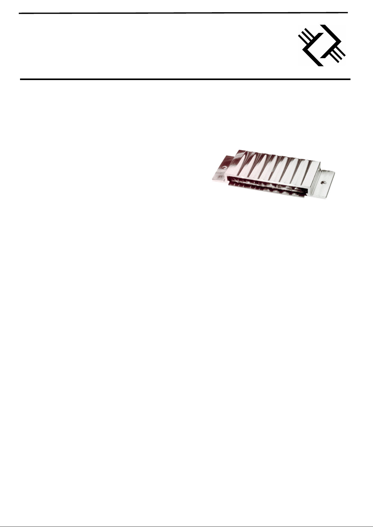
ECM-600H
600W RMS CLASS D AUDIO AMPLIFER MODULE
FEATURES
• HIGH POWER: 600W RMS
1
• HIGH EFFICIENCY ~90%
• HIGH SWITCHING FREQUENCY: 450KHz.
• LOW DISTORTION: <0.3% THD OPEN LOOP
• SIMPLE POWER SUPPLY REQUIREMENT
2
• THERMALLY EFFICIENT PACKAGE:
-INTEGRAL HEATSINK
-NO COOLING FANS REQUIRED
• LOW NOISE: NOISE FLOOR typ. 85dB DOWN
3
• EMC SCREEN INTEGRAL TO PACKAGE
• OVER TEMPERATURE PROTECTION OPTION
4
• OVER CURRENT PROTECTION OPTION
4
-PULSE BY PULSE
• LOW QUIESCENT CURRENT - MUTE FACILITY
• DRIVES A 16Ω, 8Ω AND 4Ω SPEAKER
5
• SLAVE MODULES CAN BE LINKED TO BOOST
DRIVE CAPABILITY (WITH MASTER OPTION)
• OTHER POWER OPTIONS AVAILABLE
1
• LOW COST
• LIGHTWEIGHT
• CUSTOM AMPLIFIER DESIGNS AVAILABLE
NOTES
1) Other power options include 2000W, 1000W, 300W, 150W and
50W. Alternately, custom power levels can be produced.
2) Companion PSU unit will be available early 2000
3) Assumes minimisation of external noise coupling and measured in
audio band only.
4) Contact Profusion for more details of these options
5) 2Ω speaker variant available
APPLICATIONS
• PROFESSIONAL AUDIO POWER AMPLIFIER
• ACTIVE SPEAKER SYSTEMS
• ACTIVE SONAR SYSTEMS
• NOISE CANCELLATION SYSTEMS
• MOTOR / MAGNET DRIVE MODULES
• POWER CONVERSION
• UPS - SINE WAVE INVERTER
DESCRIPTION
The ECM-600H is a complete professional audio power
amplifier module. The module contains power transistor
drive electronics, control and protection circuitry. Only a
power supply, decoupling capacitors and output filter
(optional) must be added to produce a stand alone
professional audio amplifier. The module is optimised to
drive a 4Ω load (16Ω, 8Ω and 2Ω optimised versions are
available). Modules can be ganged together to produce a
stereo amplifier. For higher power applications the
ECM-600H/SL slave module can be linked to the power
amplifier to increase the drive capability.
Please contact Profusion for a confidential discussion of
your requirements and further application information.
CLASS D AUDIO AMPLIFER MODULE
Page 2
Profusion plc - Aviation Way - Southend-on-Sea - Essex - SS2 6UN UK
Tel: +44(0) 1702 543500 Fax: +44(0) 1702 543700 email:sales@profusionplc.com Website: www.profusionplc.com
Rail voltage, VRS ……………………………………………………………………..….... 100 V
Control voltages VL ………………………………………………………………………… +18 V
Total current into VL ..……………………………………………………………………. 150 mA
Operating free air temperature, TA …...…………………………………………… -10°C to 40°C
Storage temperature range, T
stg
…………………………………………………….. -40°C to 70°C
PCB solder pad temperature for 60 secs ……..…………………………………………….. 260°C
Stresses beyond those listed under absolute maximum ratings may cause permanent damage to the device. These are stress ratings only and functional operation
of the device at these or any other conditions beyond those indicated “recommended operating conditions” is not implied.
Recommended operating conditions
MIN TYP MAX UNIT
RAIL VOLTAGE, V
RS
0 65 80 V
POWER SUPPLY VOLTAGES, +V
L
10 12 14 V
AUDIO INPUT, S
2
0 +1 +1.09 Vp-p
MODULATION FACTOR 0 0.9 0.98
OPERATING FREE AIR TEMPERATURE, T
A
10 60
°C
Electrical characteristics at a free air temperature of 25°°C
VALUE
PARAMETER NOTES/TEST CONDITIONS VRS = 65 V UNIT
MIN TYP MAX
S
3
ENABLE INPUT
(Other input options available)
LEAVE UNCONNECTED OR
CONNECT TO 0V TO ENABLE
4.75 5 5.25 Vp-p
R
EN
ENABLE INPUT IMPEDANCE
10
KΩ
R
IN
AUDIO INPUT IMPEDANCE
(Other input options available)
7.3
KΩ
I
L
POWER SUPPLY CURRENT
RL = 4Ω
100 150 mA
I
RS
POWER RAIL CURRENT
RL = 4Ω
16
A
P
RR
ALLOWABLE POWER RAIL
RIPPLE
SEPARATE POWER SUPPLY
MODULE AVAILABLE
1 %
r
O
OUTPUT RESISTANCE
RL = 4Ω
100
mΩ
SNR SIGNAL TO NOISE RATIO
RL = 4Ω (in audio band)
-85 dB
f
SW
SWITCHING FREQUENCY
(Provisional)
450 KHz
t
PD
PROPAGATION DELAY
(POWER OUTPUT STAGE)
RL = 4Ω
150 ns
SPECIFICATIONS
Absolute maximum ratings
Page 3
Profusion plc - Aviation Way - Southend-on-Sea - Essex - SS2 6UN UK
Tel: +44(0) 1702 543500 Fax: +44(0) 1702 543700 email:sales@profusionplc.com Website: www.profusionplc.com
The total coupled power from the input of the amplifier to the load is determined by three parameters.
These are:
1. The input signal level with respect to the maximum input level (Modulation factor)
2. The Inherent efficiency of the amplifier module.
3. The attenuation of the audio signal by the output filter (Filter attenuation).
Modulation Factor
The maximum input audio signal level for the amplifier is normally +1V peak to peak. For signal levels
greater than this range the amplifier will 'clip' which will produce a distorted signal. Driving the amplifier
into clip will not damage the module but will severely degrade the replication of the audio signal and can
in some cases damage the loudspeakers. At + 1V peak to peak the modulation factor is 0.9 i.e. the input
signal is at 90% of the full input range. If the input signal magnitude is well controlled, higher modulation
factors can be used. In practice 0.98 modulation factor (+1.09V peak to peak) should be considered the
absolute maximum and 0.95 (+1.05V peak to peak) should be adopted in applications where maximum
power coupled to the loudspeaker load is desirable. If the amplifier module is to be used at high
modulation factors we recommend using an anti-clip circuit. This circuitry can either be added by the user
external to the module or selected anti-clip options can be incorporated in to the package. For the various
options, please see the later section or contact Profusion.
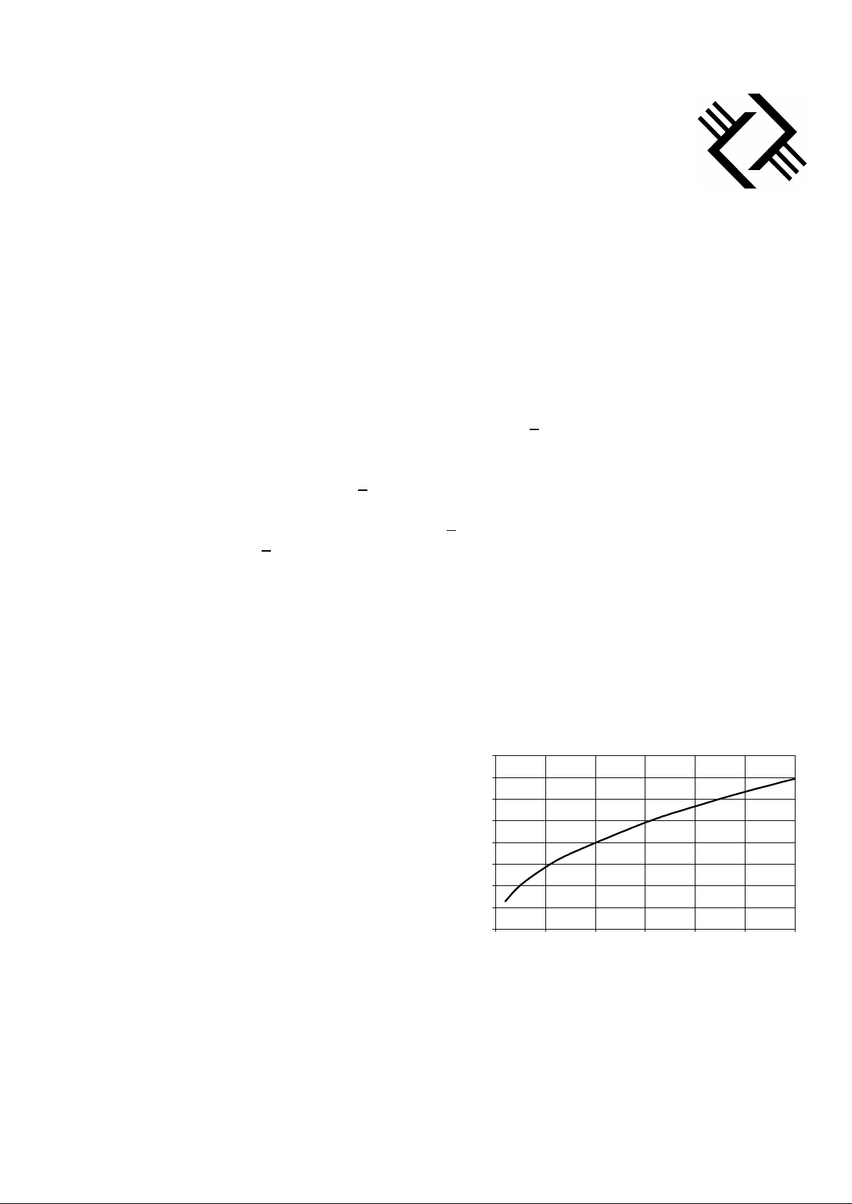
Inherent Efficiency
The amplifier modules are tested for the inherent
efficiency by measuring the power coupled into the
defined load (non-inductive dummy load). To calculate
the inherent efficiency, the differential voltage across
the load is measured for the defined rail voltage. The
control of the power output from the amplifier module
is achieved by varying the rail voltage. At a given rail
voltage the maximum theoretical output power is
given by the chart opposite.
For example, if the rail voltage is 20V and the
differential voltage across the load is measured at 38V,
the power into a 4Ω load would be:
OUTPUT POWER and EFFICIENCY
Total coupled power
Rail voltage versus maximum power into
a pure 4 ohm pure resistive load
0
10
20
30
40
50
60
70
80
0 100 200 300 400 500 600
Power (W)
Rail voltage (V)
Measured power = (38/2)2/(4 * 2) or 45Wrms
Page 4

Profusion plc - Aviation Way - Southend-on-Sea - Essex - SS2 6UN UK
Tel: +44(0) 1702 543500 Fax: +44(0) 1702 543700 email:sales@profusionplc.com Website: www.profusionplc.com
From the chart above:
Maximum theoretical output power at 20V = 50Wrms.
Then, the Inherent Efficiency of the amplifier module is 90%.
In practice, the quality of the amplifier terminations can affect the Inherent Efficiency, for maximum
efficiency the power connections (Rail voltage, Output terminals and the power ground) should be made
with soldered connections. If losses in the wiring to the load are minimised Inherent Efficiencies of 95% are
achievable.
Filter Attenuation
The direct output from the amplifier module is a pulse
width modulated signal. The underlying audio signal
has been mixed inside the amplifier with a switching
frequency at 450KHz. It is possible to connect the
amplifier output directly to a loudspeaker and produce
acceptable performance. However, if the speaker is
remote from the amplifier or sensitive high frequency
tweeters are being used it is advisable to filter out the
switching frequency.
Design of a high efficiency, flat passband filter with
maximum attenuation of the switching frequency is not
trivial. Hence, the audio amplifier output filter
requirements are minimum attenuation and distortion
in the passband from 20Hz to 20KHz. Thereafter
maximum attenuation at the switching frequency. The
load for the filter is a 4Ω loudspeaker which could
vary dynamically from 1Ω to 8Ω. If a simple LC
lowpass filter is used to minimise the attenuation in the
audio band of frequencies, the attenuation of the
modulation fundamental frequency will be typically
25dB. In addition, any gain peaking introduced by the
simple filter will distort the upper frequency ranges of
the audio band and introduce instabilities. In some
applications this simple filter could be acceptable,
However, for more demanding applications, a filter
that provides greater than 40dB attenuation of the
switching frequency, whilst providing a flat audio
passband with less than 0.5dB attenuation is available.
For more details of alternative filter combinations
please contact Profusion.
Simple LC filter with gain peak
-60.00
-50.00
-40.00
-30.00
-20.00
-10.00
0.00
10.00
20.00
30.00
1,000 10,000 100,000 1,000,000
Frequency (Hz)
Transmission (dB)
L
C
L
C
SDV1015-600
POWER AMPLIFIER
MODULE
OUT1
OUT2
Page 5

Profusion plc - Aviation Way - Southend-on-Sea - Essex - SS2 6UN UK
Tel: +44(0) 1702 543500 Fax: +44(0) 1702 543700 email:sales@profusionplc.com Website: www.profusionplc.com
When calculating the total coupled power the combined
effects of the above parameters must be considered.
One final parameter that will affect the total coupled
power that is within the control of the user is the wiring
resistance. It is important to minimise the resistance of
the cableforms from the amplifier to the filter (if used)
and from the filter to the loudspeaker. For example,
0.1Ω of cable resistance will form a potential divider
with the speaker load. For a 4Ω load the power loss due
to this wiring resistance is 0.4dB.
If the total coupled power into the load is expressed in decibels of loss (excluding wiring resistance)
then:
Total coupled power = theoretic output power + modulation factor + inherent efficiency + Filter attenuation
Using our patented filter design, and maximum modulation factor, it is possible to achieve total coupled power
figures of 85% or -1.4dB attenuation in the audio pass band.
To minimise quiescent power dissipation the output power stage of the module can be disabled using the enable (S3)
input.
DISTORTION and NOISE
The noise characteristics of the ECM-600H amplifier module are different from a linear amplifier in that
the dominant source of 'noise' is the amplifier switching frequency. This frequency at 450KHz is present
even when no audio signal is input to the amplifier. The switching signal is a square wave and will have
harmonics of the fundamental frequency e.g. 1.350MHz, 2.25MHz, 3.15MHz etc. The output filter if used,
must attenuate this signal and let the audio signal through without attenuation or distortion. A specially
designed filter configuration is available that is able to effectively attenuate the switching signal and leave
the audio signal unaffected.
Using this filter technology it is possible to attenuate the fundamental of the switching frequency by about
40dB. This filter produces a flat audio passband irrespective of variations in the loudspeaker load, with 5%
power loss in the audio passband. Greater attenuation of the switching frequency can be achieved if more
attenuation in the audio band is permitted. Profusion is able to supply filters designed to a custom
requirement.
To minimise external interference signals the audio connection to the amplifier should be via a low noise
screened cable. The amplifier module should not be positioned directly adjacent to mains or similar high
level voltages. The power supply used to supply the rail voltage should be regulated with a minimum ripple
level of 1% or less.
Page 6

Profusion plc - Aviation Way - Southend-on-Sea - Essex - SS2 6UN UK
Tel: +44(0) 1702 543500 Fax: +44(0) 1702 543700 email:sales@profusionplc.com Website: www.profusionplc.com
THERMAL EFFICIENCY
The ECM-600H amplifier module comes housed in an aluminium package. Internal to the package, the
power components are thermally bonded to the housing. The housing is also electrically bonded to the
supply ground. The thermal resistance of the amplifier package in free air is 4°C/W (θa). The contact
thermal resistance of the amplifier can be assumed to be 0.5°C/W (θc).
To decide whether additional heatsinking is required the power level and duty cycle of the music must be
estimated. The power level should be determined from the maximum power the unit is asked to produce and
is determined by the rail voltage (see above chart of rail voltage versus power into a 4Ω load). Assuming an
inherent efficiency of 95% means that 5% of the rated power will be dissipated inside the amplifier module.
For example, a maximum theoretical output power of 600W, 30W will be dissipated inside the amplifier
unit. This assumes a continuous sine wave input at full modulation factor, somewhat unrealistic for audio
signals with their associated latency. The actual power levels with audio signals would typically be 25% of
the calculated value. If this figure is used then the power dissipation inside the module would be 7.5W.
Once the typical power dissipated inside the module is known the temperature rise using the module at this
power can be calculated. The temperature rise is given by:
Temperature rise = θa * power dissipation (°C)
With the example above, the temperature rise would be 22.5°C above ambient temperature. The operational
temperature of the module should not exceed 70°C. If the calculated temperature rise and the maximum
ambient temperature for operation will exceed this figure, then additional heatsinking will be required. If
heatsinking is required then the module can be mounted onto an additional heatsink. When mounting to a
heatsink, it is recommended that a high thermal conductivity electrical insulating mat is used. If the thermal
resistance of the new heatsink is θh, then:
Temperature rise = (θc + θh) * power dissipation (°C)
If a heatsink with a thermal resistance of 1.5°C/W is selected, then in the above example the temperature
rise above ambient would be 15°C.
INPUT CHARACTERISTICS
The input impedance of the standard amplifier module is 7.3KΩ. This value was chosen to provide the best
balance between ensuring sufficient impedance to the audio source and minimising the affects of external
interference. The amplifier input is differential to ensure common mode noise rejection. The bandwidth of
the input amplifier is 80KHz (3dB). This wide bandwidth is designed to afford maximum flexibility to the
user. For purely audio applications, an input filter can be incorporated prior to the amplifier module. This
additional circuitry can be incorporated as an option inside the amplifier package or alternatively can be
configured external to the amplifier. For further discussions of these options, please contact Profusion.
Page 7

Profusion plc - Aviation Way - Southend-on-Sea - Essex - SS2 6UN UK
Tel: +44(0) 1702 543500 Fax: +44(0) 1702 543700 email:sales@profusionplc.com Website: www.profusionplc.com
MECHANICAL DETAILS
Connections
The amplifier module has been designed such that connections can be made with an
edge connector. The edge connector should have the following specification:
Number of ways 32
Pitch 2.54mm (0.1")
Card aperture 82.1mm
Card insertion depth (max) 8.5mm
Working voltage 500VDC
Current per contact 5A
Contact resistance
10mΩ
Breakdown voltage 1KV
Insulation resistance
5 x 10⁹Ω min.
Temperature range
-40°C to +100°C
Insertion / Extraction force 150g max.
The connector connections are (from left to right with connections uppermost) :
Way Identifier Function Remarks
1 S2 Signal ground Connect to input cableform screen
2 No connection leave free
3 S1 Audio signal +1Vp-p @ 90% modulation factor (this is a differential input)
4 No connection leave free
5 S2 Signal ground Connect to input cableform screen
6 No connection leave free
7 S3 Enable Leave unconnected to enable, connect to +5VDC to disable
8 No connection leave free
9 VL+ Positive supply +10.0 +0.2/-0.1VDC @ 100mA
10 No connection leave free
11 VL- Negative supply -10.0 +0.1/-0.2VDC @50mA
12 No connection leave free
13-15 GND Power ground Connect across all three contacts
16 No connection leave free
17-19 OUT1 Power output To filter or loudspeaker
20-24 No connection leave free
25-27 OUT2 Power output To filter or loudspeaker
28 No connection leave free
29-31 V
RS
Rail voltage +10V to 80VDC, connect across all three contacts
32 No connection leave free
In addition to the above, it is recommended that a 100µF, 100VDC electrolytic and a low ESR 0.22µF
capacitor are connected across the ground and rail voltage terminations as close as possible to the
terminations or connector.
Page 8

Profusion plc - Aviation Way - Southend-on-Sea - Essex - SS2 6UN UK
Tel: +44(0) 1702 543500 Fax: +44(0) 1702 543700 email:sales@profusionplc.com Website: www.profusionplc.com
Rail Voltage versus maximum theoretical power into load
0
10
20
30
40
50
60
70
80
0 100 200 300 400 500 600
Power (W)
Rail voltage (V)
8Ω
16Ω
Package dimensions
(All dimensions in mm)
OPTIONS
Various options to the basic amplifier module are available. These options are
described below. If a required option is not found please contact Profusion. Custom
requirements are subject to a minimum order quantity.
Alternative load configurations
The ECM-600H module is designed to drive into a
4Ω load. Higher value loads can be used with the
amplifier, but with proportionally less power at the
same rail voltages. To increase the power coupled to
the load, the rail voltages will have to be increased. If
higher power levels than those shown on the graph
below are required then Profusion can produce a
specific variant to drive the alternative load. Contact
Profusion for further details.
Page 9

Profusion plc - Aviation Way - Southend-on-Sea - Essex - SS2 6UN UK
Tel: +44(0) 1702 543500 Fax: +44(0) 1702 543700 email:sales@profusionplc.com Website: www.profusionplc.com
Current monitor
The standard amplifier module does not include short circuit protection. The current
monitor enables precise measurement of the amplifier output current and responds in
just over 2µs to a short circuit condition. The current monitor is a coarse measure
due to the nature of loudspeaker loads. The load will fluctuate due to its reactive
nature and any current monitor has to allow peak current five times greater than the
rms currents. However, if the amplifier module is to be used in situations where the
output could be shorted (i.e. during assembly of sound systems), then this option
should be considered. The current monitor circuitry can be mounted inside an
enlarged module package.
Input characteristics
The input characteristics of the standard module can be tuned to the requirements of different applications.
Input parameters that can be readily reconfigured include:
Gain: Currently configured for input voltage levels up to +1Vp-p. Other options
include 0.5Vrms, 1Vrms, 2Vrms, +0.5Vp-p, +2Vp-p, +3Vp-p.
Input impedance: Currently set at 7.3KΩ, consult Profusion for options suitable to the
application.
Filter on input: Currently set at 100KHz (-3dB point). Other options include multiple pole
lowpass filters with roll-offs up to 100KHz.
Anti-clip on input: For applications where the audio source is not well controlled, the anti-clip
circuitry can either disable the amplifier when the signal level reaches a predetermined threshold or limit internally the modulation factor such that the
amplifier will appear to clip like a linear amplifier.
Output filter
The characteristics of the output filter can be adjusted for a particular application. Parameters that can be
varied include passband attenuation, stopband attenuation, passband ripple, and switching frequency
attenuation. Some of the aforementioned parameters are coupled and cannot be considered independently.
For applications where a filter is required please discuss the requirements with Profusion.
Switch-mode, universal input, PFC, PSU module
This product is still under development, release is expected in the coming months. The power supply will be
universal input 90 to 264Vac, 50/60Hz, power factor corrected pre-regulator, providing both rail and control
voltages for the amplifier modules.
Page 10

Profusion plc - Aviation Way - Southend-on-Sea - Essex - SS2 6UN UK
Tel: +44(0) 1702 543500 Fax: +44(0) 1702 543700 email:sales@profusionplc.com Website: www.profusionplc.com
GLOSSARY
Active speaker Integrated loudspeaker and amplifier.
Audio passband Audio spectrum from 20Hz to 20KHz.
Anti-clip Circuit to correct for excessive input signals.
Class D Amplifier using pulse width modulated output stage.
Decibel Measure of relative power dB = 10logP1/P2
EMC Electro magnetic compatibility
ESR Equivalent series resistance
Filter attenuation Performance of a filter at a specific frequency or band of frequencies.
Harmonic Higher multiple of a frequency
(K)Hz (Kilo) Hertz, frequency measure
Inherent efficiency Measure of the efficiency of the amplifier module alone.
Input impedance Impedance looking into the amplifier.
Latency Description of the dynamic range of music
Modulation Factor Ratio of input signal amplitude to maximum permissible signal amplitude.
Noise floor Residual noise level of the amplifier expressed in dB.
Output impedance Source impedance seen looking into the amplifier output.
PCB Printed circuit board
PFC Power factor corrected
p-p Peak to peak measurement
PSU Power supply unit
PWM Pulse width modulation
Quiescent current Current consumed by amplifier with no audio signal input.
Rms Root mean square = Vp-p/(2√2)
Slave module Additional power output stage driven from an optional master unit.
SNR Signal to noise ratio
Switching frequency Sample frequency of PWM.
THD Total harmonic distortion - measure of the accuracy with which an amplifier
replicates an input sine wave.
Theoretical output power Maximum output power of amplifier module, alone assuming 100%
efficiency.
Thermal resistance Measure of heatsink efficiency
Total coupled power Actual power coupled from amplifier to load (loudspeaker)
UPS Uninterruptable power supply
 Loading...