

Page 1

NTE787
Integrated Circuit
AM Receiver Subsystem
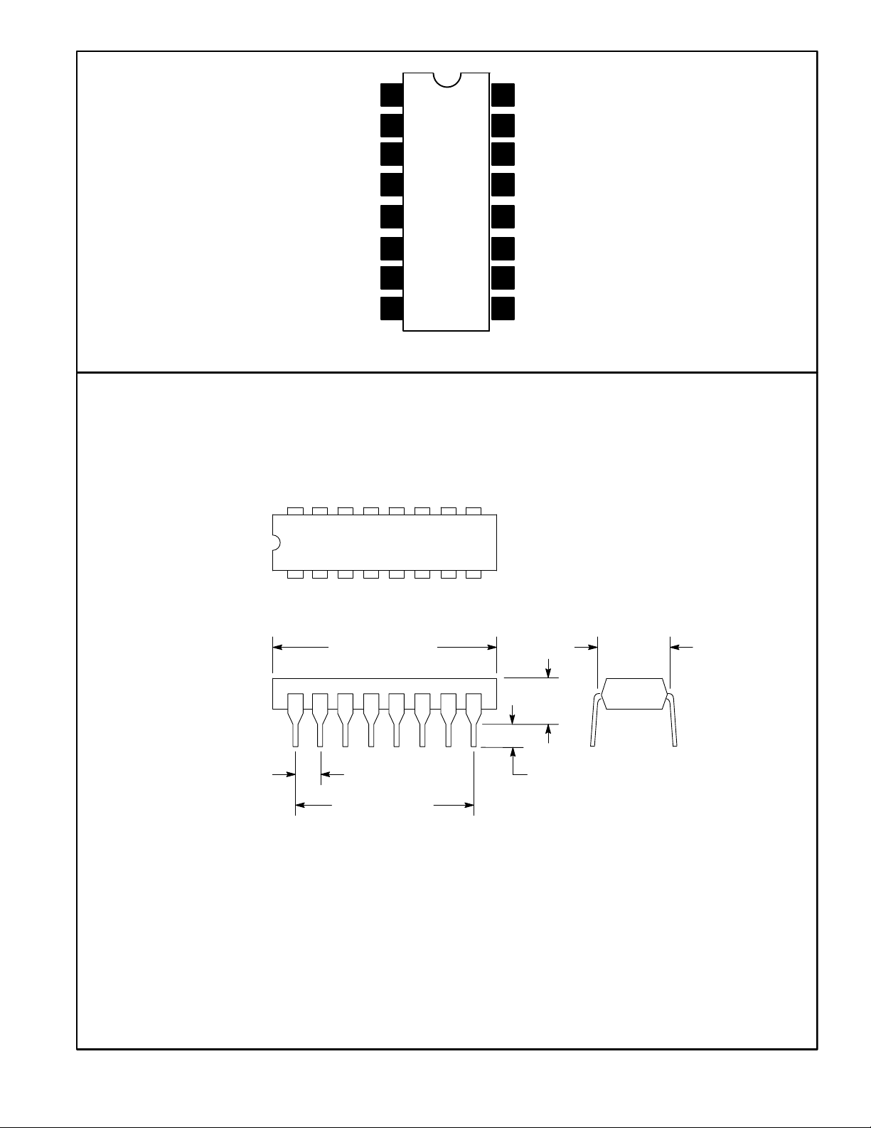
16−Lead DIP Type Package
For Applications in a variety of AM broadcast and communications receivers and applications
requiring an array of amplifiers.
Description:
The NTE787, a monolithic integrated circuit, is an AM subsystem that provides the converter, IF amplifier, detector, and audio preamplifier stages for an AM receiver. It also provides internal AGC for the
first IF amplifier stage, delayed AGC for an optional external RF amplifier, a buffer stage to drive a
tuning meter, and terminals facilitating the optional use of a tone control.
This device features four independent transistor amplifiers, each incorporating internal biasing for
temperature tracking. These amplifiers are particularly useful in general−purpose amplifier, oscillator,
and detector applications in a wide variety of equipment designs.
The NTE787 utilizes a 16−Lead DIP package and operates over an ambient temperature range of
−40 to +85C.
Features:
D Excellent overload characteristics
D AGC for IF amplifier
D Buffered output signal for tuning meter
D Internal Zener diode provides voltage regulation
D Two IF amplifiers stages
D Low−noise converter and first IF amplifier
D Low harmonic distortion (THD)
D Delayed AGC for RF amplifier
D Terminals for optional inclusion of tone control
D Operates from wide range of power supplies: V+ = 6 to 16 volts
D Optional AC and/or DC feedback on wide−band amplifier
D Array of amplifiers for general−purpose applications
D Suitable for use with optional external RF stage, either MOS or bipolar
Page 2

Absolute Maximum Ratings: (TA = +25C unless otherwise specified)
DC Supply Voltage (Across Pin5 and Pin3, Pin6, Pin13, Pin16 respectively) 16V................
DC Current
At Pin3, Pin6, Pin13, Pin16 respectively 10mA.......................................
At Pin10 30mA..................................................................
Device Dissipation (Up to T
Derate Above T
A
Operating Ambient Temperature Range, T
Storage Temperature Range, T
= +50C), P
A
D
= +50C 7.6mW/C...............................................
opr
stg
Lead Temperature (During Soldering, 1/32” from case, 10sec max), T
Electrical Characteristics:
Parameter Symbol Test Conditions Min Typ Max Unit
Static Characteristics
DC Voltage
Pin1, Pin4, Pin9, Pin11
Pin2, Pin7, Pin8 V2, V7, V
Pin10 V
Pin12 V
Pin15 V
DC Current
Pin3
Pin6 I
Pin10 I
Pin13 I
Pin16 I
Dynamic Characteristics
(TA = +25C, V+ = 12V unless otherwise specified)
V1, V4, V9, V
I
10
13
16
11
8
10
12
15
3
6
760mW.........................................
−40 to +85C..................................
−65 to +150C..........................................
L
− 0.7 − V
− 1.4 − V
− 5.6 − V
− 0 − V
− 3.5 − V
− 0.35 − mA
− 1.0 − mA
− 20 − mA
− 0 − mA
− 1.2 − mA
+265C.................
Detector Output 30% Modulation − 75 − mV
Audio Amplifier Gain A
AF
Audio Distortion V
f = 1kHz − 30 − dB
= 100mV − 0.2 − %
OUT
Sensitivity
At Converter Stage Input
At RF Stage Input − 100 − V/m
fIN = 1MHz,
Signal−to−Noise Ratio (S/N) = 20dB
− 200 − V/m
Total Harmonic Distortion THD 30% Modulation − 1.0 − %
Input Resistance
At Transistor Q1
R
IN
At Transistor Q5 − 2000 −
No AGC,
Input Frequency Signal (f
) = 1MHz
IN
− 3500 −
Input Capacitance
At Transistor Q1
C
IN
− 17 − pF
At Transistor Q5 − 12 − pF
Feedback Capacitance
At Transistor Q1
C
FB
− 1.5 − pF
At Transistor Q5 − 1.5 − pF
rms
Page 3
Converter Input
Bypass
Converter Input
Pin Connection Diagram
1
2
16
15
V
CC
Audio Output
Converter Output
st
IF Amp Input
1
3
4
5Substrate GND
st
IF Amp Output
1
nd
IF Feedback
2
2nd IF Amp Input
6
7
8
16 9
14
From Detector Filter
AGC Output from
13
RF Amp
12
To Tuning Meter
11 AGC Filter
V
CC
10
To Detector Filter
9
& Audio
18
.260
.870 (22.0)
Max
(6.6)
Max
.200 (5.08)
Max
.100 (2.54)
.099 (2.5) Min
.700 (17.78)
 Loading...