

Page 1
E-blocks™ Bluetooth board
Document code: EB024-30-2
Bluetooth board
EB024-00-2
Technical datasheet
Contents
1. About this document.................................................................................................................................................................. 2
2. General information................................................................................................................................................................... 3
3. Board layout .............................................................................................................................................................................. 4
4. Testing this product................................................................................................................................................................... 5
5. Circuit description ..................................................................................................................................................................... 7
Appendix 1 Circuit Diagram
Copyright © Matrix Multimedia Limited 2006 page 1
Page 2

E-blocks™ Bluetooth board
Document code: EB024-30-2
1. About this document
This document concerns the E-blocks Bluetooth board code EB024 version 2.
The order code for this product is EB024.
1. Trademarks and copyright
PIC and PICmicro are registered trademarks of Arizona Microchip Inc.
E-blocks is a trademark of Matrix Multimedia Limited.
2. Other sources of information
There are various other documents and sources that you may find useful:
Getting started with E-Blocks.pdf
This describes the E-blocks system and how it can be used to develop complete systems for learning electronics and
for PICmicro programming.
PPP Help file
This describes the PPP software and its functionality. PPP software is used for transferring hex code to a PICmicro
microcontroller.
C and assembly strategies
Not provided for this product.
3. Disclaimer
The information in this document is correct at the time of going to press. Matrix Multimedia reserves the right to
change specifications from time to time. This product is for development purposes only and should not be used for
any life-critical application.
4. Technical support
If you have any problems operating this product then please refer to the troubleshooting section of this document
first. You will find the latest software updates, FAQs and other information on our web site:
www.matrixmultimedia.com . If you still have problems please email us at: support@matrixmultimedia.co.uk.
Copyright © Matrix Multimedia Limited 2006 page 2
Page 3

E-blocks™ Bluetooth board
Document code: EB024-30-2
2. General information
Description
This E-blocks™ board contains a TDB BLU2i V2 module which adds Bluetooth functionality to your E-blocks
system. The class 1 Bluetooth module has a transmit power of 6dBm which should give a 100 yard transmission
range at a data transfer rate of 100Kbps. The module is programmed using the serial I
command superset, and can be interfaced to any microcontroller with a UART facility. The module is capable of
supporting a range of Bluetooth protocols including LAP, Data, and the headset profile. A compatible E-blocks
CODEC board for establishing headset audio transfer is available. Flowcode macros to support the use of this board
are available.
Features
• E-blocks compatible
• Low cost
• Provides a Bluetooth interface for all your projects
2
C interface
• I
• 100 yard range
• Supports most Bluetooth protocols
2
C protocol, with an AT
Copyright © Matrix Multimedia Limited 2006 page 3
Page 4

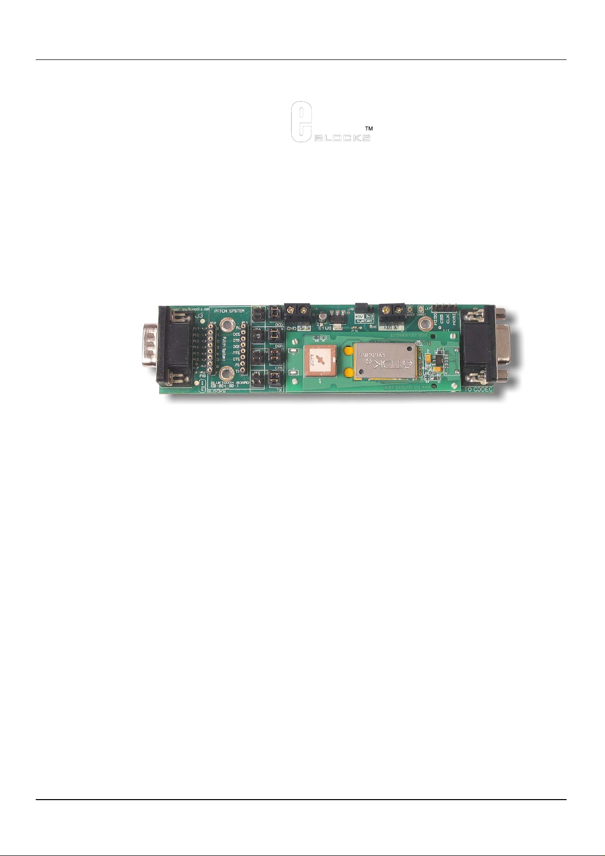
3. Board layout
E-blocks™ Bluetooth board
Document code: EB024-30-2
1. D-type E-blocks connector - to Programmer board
2. Patch system
3. Connection jumpers
4. BLU2i V2 module
5. Power in screw terminals - +5 Volts and Ground for EB024 power supply
6. operating voltage selector – 3.3V/5V voltage out selector
7. Power out screw terminal – for powering CODEC board and other peripherals.
8. BLU2i programmer connector
9. D-type E-blocks connector – to CODEC board
Copyright © Matrix Multimedia Limited 2006 page 4
Page 5

E-blocks™ Bluetooth board
Document code: EB024-30-2
4. Testing this product
The following program will test the circuit. The test files can be downloaded from
The following instructions explain the steps to test your USB232 board. The instructions assume that PPP is
installed and functional. It also assumes that you are confident in sending a program to the PIC via the
Multiprogrammer.
These programs require a PICmicro Multiprogrammer board (EB-006) with a 40-pin PIC16F877A device. They also
require a PC with FTDI drivers installed, MProg 2.3 software, a spare USB port and Hyperterminal.
The program will enable you to fully test the functionality of the board.
1. System Setup
Master system:
EB006 Options Setting
Power supply External, 14V
PICmicro device 16F877A
SW1 (Fast/Slow) Don’t care
SW2 (RC/Xtal) Xtal
Xtal frequency 19.6608MHz
Port A Switch board EB007
Port B LCD display EB005
Port C Bluetooth board
EB024
Port D
Port E
Test program
EB005 Options Setting
J3,J4 DEFAULT
EB024 Options Setting
J7 No link block
J8 5V
J13 / J9 J9 Horizontal
J14 / J10 J10 Horizontal
J15 / J11 J11 Horizontal
J16 / J12 J12 Horizontal
Address (set by software) 00809094BA05
Slave system:
EB006 Options Setting
Power supply External, 14V
PICmicro device 16F877A
SW1 (Fast/Slow) Don’t care
SW2 (RC/Xtal) Xtal
Xtal frequency 19.6608MHz
Port A Switch board EB007
Port B LCD display EB005
Port C Bluetooth board
BT_MASTER.HEX
EB024
www.matrixmultimedia.com.
Copyright © Matrix Multimedia Limited 2006 page 5
Page 6

E-blocks™ Bluetooth board
Document code: EB024-30-2
Port D
Port E
Test program
BT_SLAVE.HEX
EB005 Options Setting
J3,J4 DEFAULT
EB024 Options Setting
J7 No link block
J8 5V
J13 / J9 J9 Horizontal
J14 / J10 J10 Horizontal
J15 / J11 J11 Horizontal
J16 / J12 J12 Horizontal
Connect “+V” from the Screw terminal of the Switch board to “+V” of the Multiprogrammer, the LCV board, and
the Bluetooth board – 5V input.
2. Test Procedure
1. Before the test unit has been connected, connect both systems as described and apply the power to the Master
EB-006 E-Block and press “RESET” – “init..done” will be displayed on the Master LCD.
2.
A series of dots on the Master LCD will show the progress of the Master System boot procedure. The message
“setup” will indicate a successful boot, and then the screen will go blank.
3.
Connect +5V to unit under test and then connect it to Port C of the Slave System. LED’s on Bluetooth module
will light briefly which indicate that the Module is ‘alive’. Press “RESET” on the Slave EB-006.
“rx.done.” will be displayed on the Slave LCD, then the screen will go blank and a series of dots will indicate
4.
progress. This will end with “connected”, followed by the messages “sending…” and “press A0”. This whole
sequence should take approximately 10 seconds.
5.
While this is happening, the Master LCD will display “PAIR 0 xxx”, “RING xxx” and “CONNECT xxx”
messages (where “xxx” is a 12-digit number), and finally “*Unit passed*”. At this stage, both the Master and
Slave Bluetooth modules will have D2 on the module lit.
6.
Press “A0” on the Switch E-Block of the Slave System. This will reset the test unit. The Slave LCD should
display “*** DONE ***” and the Master LCD should display “^^^” and “NO CARRIER”. Also, the D2 LEDs
on the Bluetooth modules should turn off.
7. Remove the test EB-024 unit from the Slave System and repeat the above from step 3. There is no need to re-
boot the Master System, although the Master LCD display can be cleared by pressing A0 on the Master Switch
E-Block if required.
3. Possible problems
1. If the Slave Bluetooth module does not have power (or is not working for any reason), the Slave LCD will
display “rx.done.f0” at step 4.
2. If the Master System boot fails, the LCD will display “init.done” and the screen will go blank. The progress
dots will not appear.
3. If the Slave module fails to “discover” the Master module, the Slave display will stall at 4 dots and finally a
message “error 6” will be displayed. Possible causes are that the Master Bluetooth module…
i. …is no longer powered
ii. …has not completed boot-up successfully
iii. …is not the one with address “00809094BA05”
iv. …remains connected to another Bluetooth module (the D2 LED will be on)
4. Reset the Master System and wait for a successful boot-up to recover.
Copyright © Matrix Multimedia Limited 2006 page 6
Page 7

E-blocks™ Bluetooth board
Document code: EB024-30-2
5. Circuit description
Max 3002 Chip
Coverts the 5V I/O from the PICmicro Multiprogrammer in to 3.3V for the Codec board.
U1 Blui Connector
Connects the Blui V2 Bluetooth Module to the Circuit Board
Copyright © Matrix Multimedia Limited 2006 page 7
Page 8

Page 9

Appendix 1 – Circuit diagram
 Loading...