

Page 1
E-blocks™ internet board
Document code: EB023-30-1
Internet board datasheet
EB023-00-1
Contents
1. About this document ......................... ..... .. .. ... .... ... .. .. ..... .. ... .. ..... .. ... .. ..... .. .. ... .... ... .. .. ..... .. ... .. ...........................................................2
2. General information ................................................. ...................................................... ................................................................3
3. Board layout...................................................................................................................................................................................4
4. Testing this product...................... ... .. ..... .. .. ... .... ... .. .. ... ..... .. .. ... .. ..... .. .. ... .. ..... .. .. ... .. ..... .. .. ................................. ...............................5
5. Circuit description........................................................................................ ........................................................ ..........................9
Appendix 1 Circuit diagram
Copyright © M atrix Multimedia Limited 200 5 page 1
Page 2

E-blocks™ internet board
Document code: EB023-30-1
1. About this document
This document concerns the E-blocks intenet board code EB023 version 1.
The order code for this product is EB023.
1. Trademarks and copyright
PIC and PICmicro are registered trademarks of Arizona Microchip Inc.
E-blocks is a trademark of Matrix Multimedia Limited.
2. Other sources of information
There are various other documents and sources that you may find useful:
Getting started with E-Blocks.pdf
This describes the E-blocks system and how it can be used to develop complete systems for learning electronics and
for PICmicro programming.
PPP Help file
This describes the PPP software and its functionality. PPP software is used for transferring hex code to a PICmicro
microcontroller.
C and assembly strategies
This is available as a free download from our web site.
3. Disclaimer
The information in this document is correct at the time of going to press. Matrix Multim edia r eser ves the right to
change specifications from time to time. This product is for development purposes only and should not be used for
any life-critical application.
4. Technical support
If you have any problems operating this product then please refer to the troubleshooting section of this document
first. You will find the latest software updates, FAQs and other information on our web site:
www.matrixmultimedia.com
.
Copyright © M atrix Multimedia Limited 200 5 page 2
Page 3
E-blocks™ internet board
Document code: EB023-30-1
2. General information
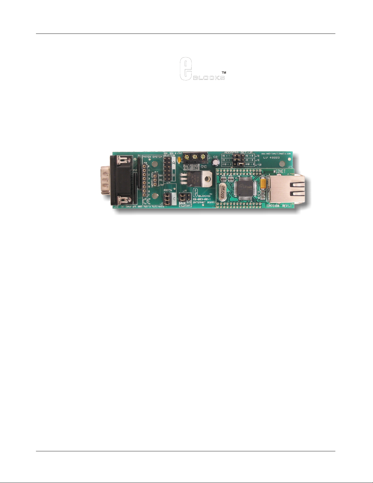
1. Description
The Internet E-Block allows Internet and Ethernet capabilities to be easily added to your microprocessor and FPGA
designs. It consists of a TCP/IP stack, a physical-layer chip and an Etherne t socket.
Communication between this E-Block and a microcontroller is achieved using an I
Two Flowcode components are available that simplify the use of this E-Block. The first is a "WebServer"
component that facilitates the creation of an embedded web server with no knowledge of TCP/IP protocols needed.
The second Flowcode component, the "TCP/IP" compone n t, allows user s to create a custom appl ica tio n using
various protocols (TCP, UDP, IP or Ethernet), such as ARP scanners, SMTP email clients, har dware firew alls, etc,
etc.
'C' and Assembly users can access all the features of this device without the need to embed an extensive TCP/IP
stack into their own firmware.
2. Features
• E-blocks compatible
• Supports 10/100 Base TX
• Supports half/full duplex operatio n
• Supports Auto-negotiation
• IEEE 802.3/802.3u Compliant
• Operates with 3.3V or 5V systems
• Supports network status indicator LED’s
• Includes hardware Internet protocol s: TCP, IP Ver.4, UDP, ARP
• Includes hardware Ethernet protocols: DLC, MAC
• Supports 4 independent connections simultaneous l y
• Supports I
• Two Flowcode Components are available
o WebServer to allow simple cre ati on of em bedded w eb con tent
o TCP_IP to allow custom communications using various protocols (TCP, UDP, IP or Ethernet la yers)
2
C bus interface with 8 available addresses
2
C© interface.
3. Block schematic
3
Address
Selection
Block schem a tic
Internet Module
1
8
3
SDA,
SCK
& /INT
hardwre
stack
+3.3V
Voltage selection
PHYTCP/IP
+5V
Copyright © M atrix Multimedia Limited 200 5 page 3
RJ45
Ethernet
Cable
Connector
Page 4
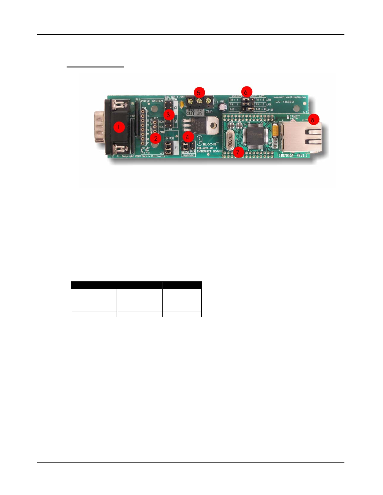
3. Board layout
E-blocks™ internet board
Document code: EB023-30-1
EB023-74-1.cdr
1) 9-way downstream D-type connector
2) Patch system
3) SDA, SCK & /INT selection jumper pins
4) Voltage Selection jumper
5) Power screw terminals
6) Address set-up jumpers
7) Hardware TCP/IP stack IC
8) RJ45 connector
General Guide for SDA, SCL & /INT settings:
Jumper at A Jumper at B Jumper at C
PIC16F7x
PIC16F7x7
PIC16F87x
PIC16F87xA
Connect to Port C Connect to Port B
Note: The TCP_IP Flowcode component requires MI2C (Master I
PIC16F88
PIC16F87
PIC16F818
PIC16F819
Patch System
2
C). If you wish to use standard I2C devices, such
as the PIC16F88 you may need to create your own C/ASM code.
If you are using PICmicros then select +5V systems (J5) as PICmicros operate from +5V.
Copyright © M atrix Multimedia Limited 200 5 page 4
Page 5

E-blocks™ internet board
Document code: EB023-30-1
4. Testing this product
The following program will test the circuit. The test file can be downloaded from www.matrixmultimedia.com
1. System Setup
The Internet board is connected direct to a PC using a standard RJ45 CAT 5 cross-over cable, as show n in the
example below: -
.
Multi-programmer board (EB006) with:
EB006 Options Setting
Power supply External, 14V
PICmicro device 16F877A
SW1 (Fast/Slow) Don’t care
SW2 (RC/Xtal) Xtal
Xtal frequency 19.6608MHz
Port A Switch board EB007
Port B LCD board EB005
Port C Internet board EB023
Port D
Port E
Test program EB023_test.hex
EB005 Options Setting
Patch jumper setting DEFAULT
EB023 Options Setting
Patch jumper setting A
Voltage selector J 5 5V
Address jumper J8 1
Address jumper J9 1
Address jumper J10 1
The cable between the PC Ethernet conne ctor and the internet board is a crossover cable.
2. PC System Set-up
Note that the details here may vary from Operating System to Operating System.
If the PC has been configured for use on a Local Area Network you may need to configure the PC to have a set IP
address, and to not use Proxy server s.
Copyright © M atrix Multimedia Limited 200 5 page 5
Page 6

To find the IP address of a PC do the following:
1) Go to START -> RUN and type in ‘CMD’ and click on OK.
2) A black DOS prompt window will appear.
3) Type in ‘ipconfig’ and press Enter.
4) The IP address will be listed in the data provided.
5) Type in Exit and press enter to close the window.
E-blocks™ internet board
Document code: EB023-30-1
The IP address can be set up in the Network Connections dialogue.
Open the Network Connections icon in the Control Panel.
Select the Local Area Connection item and right click and view its properties.
Select the TCP/IP entry in the list and click on the Properties button.
Go to the Alternative Configuration tab, select ‘User configured’ a nd enter the IP address obtained from the ipconfig
program into the IP address. Click on the Subnet mask and the default 255.255.255.0 setting should appear. If not
you can add it manually.
Here we have set the IP address for this PC to 192.168.0.16.
The LAN proxy server setting can be found in the Internet options control panel.
Ensure that Use a proxy server is not ticked.
Copyright © M atrix Multimedia Limited 200 5 page 6
Page 7

E-blocks™ internet board
Document code: EB023-30-1
3. Test Procedure
This test routine will test the functionality of the three main protocol layers (MA C, IP, TCP).
The program will send an HTML webpage from the PICmicro® to the computer via the Internet board and the
connecting cable.
Visual clues will appear on the LCD display to ensure that the program is running.
1) Set up the Internet system as outline above
2) Apply power to Multiprogrammer board.
3) Download the test pr ogram .
4) Press Reset bu tton o n Mult ipr ogra mmer
1. LCD display will display “Starting up…” and then “Complete” once the TCP/IP connection is
established.
5) Open up your Web browser
1. Note: Your home page may not open properly as it is not connected to your network
6) Type the following IP address in to your web browse r: htt p:// 192.1 68.0. 2
1. The LCD display will show “Sending HTML” during transmission.
7) To ensure that the page is vali d and curren t (i.e. not stored in yo ur compu ters memor y) you need to
refresh the page. Press the “Refresh” button in your Web browse r
8) The “page request” number will increment when the page is refreshed (with a rollover back to 1 upon
reaching 9)
This will confirm that the Internet Board is fully functional.
If you have problems with the refresh sequence repeat from step three above.
Troubleshooting
1) LCD fails to display “Starting up…”
1. Check power, connections, chip and check tha t the correct program has been downl oaded to
the device.
2) Displays “Startin g up…” but not “Complete.”
1. TCP/IP connection not established
2. Check Internet board has power.
3. Check cross-over cable.
3) Are the Internet board and Ethernet connection LE D’s flashing at all?
1. If they are then there is an IP Address or socket issue.
Copyright © M atrix Multimedia Limited 200 5 page 7
Page 8

E-blocks™ internet board
Document code: EB023-30-1
2. Check if PC has IP Address 192.168.0.2 and this m ay cause a conflict with the one assigned to
the Internet board.
4) Can you Ping the Internet board?
1. Use the Command prompt and enter “Ping 192.168.0.2”.
2. Check the onboard jumpers are set correctly
3. If using the patch system verify that the patch connections have been set up correctly.
Copyright © M atrix Multimedia Limited 200 5 page 8
Page 9

E-blocks™ internet board
Document code: EB023-30-1
5. Circuit description
The circuit as can be seen in the circuit diagram below (See Appendix 1 – Circuit diagram), made up of three main
components: the Hardware TCP/IP sta ck I C, the volta ge regu la tio n and select ion s yst e m, and the Patc h system .
1. Hardware TCP/IP stack IC
The Hardware TCP/IP stack IC used is the Wiznet Internet Module NM7010A (formally IIM7010A) IC. The
TCP/IP stack IC is an all-in-one network module, ideal component to develop Internet enabled systems. The
module communicates via a standard I
communicate with the module, enabling a quick development time.
2
The I
C connection uses a 7-bit address to identify each specific target. The three Least Significant Bits of the
address for the Internet module are set using the three jumpers J8, J9 and j10. This allows the use of up to 8
individual Internet boards on the same network system. For further information on the TCP/IP stack IC please see
the datasheet provided on the CD.
2. Voltage regulation / selection system
The TCP/IP stack IC requires a core voltage of +3.3Volts. However the I/O lines are +5V tolerant allowing the
board to run from either a +5V system or from a +3.3V system. The board can be used with a +5V system (i.e. EBlocks PICmicro Multiprogrammer) or a +3.3V system (i.e. E-Blocks FPGA Board). An on-board voltage regulator
is used to generate the +3.3V required by the TCP/IP stack IC.
The board is supplied with a jumper link (J5) which allows the user to select which voltage system they ar e using.
The user must position the jumper link in either the “+5V” or the “3.3V” posi tion as labelled on the PCB.
2
C compatible bus. This means that most processors ca n easily and rapidly
3. Patch system
The Internet Board, like all E-Blocks , is designed with flexibility in mind. Therefore the Internet Board can be used
with any ‘upstream’ processor board. To facilitate this a patc h system has been pr ovide d on th is boar d. This patch
system allows the use to either select the default setting of the board (gene rally used for PICmicro®
microcontrollers) or to wire the connectors to any pins of the D-Type connector that they require.
The communication between the Internet board and the ‘Up-stream’ processor board is via an I
2
C compatible bus
(SDA and SCK signals).
4. Default settings (A or B)
To use the default setting of the Internet board, the jumper links should be placed on hea der pins J6. Jumper setting
A and B are used for selecting the appropriate pins for SDA and SCK, the dedicated I
these jumper settings route the interrupt line from the Internet board to bit 0 of the ‘Up-stream’ device.
Headers pins J3 are provided to allow the use the patch settings.
The microcontroller that is being used determines which port and which jumpers are used. For example, if a
PIC16F877A is being used, the Internet board must be connecte d to Port C, with the jumper settings to A.
The following tables illustrate the c orrect jumper settings.
2
C compatible lines. Both
Copyright © M atrix Multimedia Limited 200 5 page 9
Page 10

E-blocks™ internet board
Document code: EB023-30-1
Jumper Setting
A
PIC16F72
PIC16F73
PIC16F737
PIC16F74
PIC16F747
PIC16F76
PIC16F767
PIC16F77
PIC16F777
PIC16F872
PIC16F873/A
PIC16F874/A
PIC16F876/A
PIC16F877/A
Jumper Setting
B
PIC16F87
PIC16F88
PIC16F818
PIC16F819
Jumper Setting
C
PATCH SYSTEM
CONNECT BOARD TO PORT C CONNECT BOARD TO PORT B
SDA = C4
SCK = C3
INT = C0
SDA = B1
SCK =B4
INT = B0
All connections are as s et b y the
user.
Table 1: Jumper settings for SDA, SCK & /INT se lection.
Note: The TCP_IP Flowcode component requires MI2C (Master I
2
C). If you wish to use standard I2C devices, such
as the PIC16F88 you may need to create your own C/ASM code.
5. Using splitter cables
Splitter cables can be used to connect more than one Internet board to a single programmer.
The SDA and SCK lines need to be the same for each board connected to the spl itter ca ble. However each board
requires a separate interrupt line. Due to this constraint you will need to use the pa tch system when using more than
one Internet board on a splitter cable.
• SDA – patch to same Pin (C4 or B1 etc.)
• SCK – patch to same Pin (C3 or B4 etc.)
• INT – patch to different Pins
Connection Jumper A (First board) Patch system (Second board)
SDA C4 C4
SCK C3 C3
INT C0 C1 (or any oth er unused Port C pin but C0)
6. 3.3V operation
This board is compatible with upstream boards operating off 3.3V.
Copyright © M atrix Multimedia Limited 200 5 page 10
Page 11

Appendix 1 – Circuit diagram
 Loading...