

Page 1
Advance Data Sheet
January 1999
E2560/E2580-Type 10 Gbits/s EML Modules
Features
■
Integrated electroabsorptive modulator
■
1.5 µm wavelength
■
Characterized for 10 Gbits/s operation
■
For use up to 80 km at 10 Gbits/s
■
Low modulation voltage
■
Temperature stabilized
■
Available with and without integral driver IC
■
Wavelength selectable to ITU-T standards
■
Ultrastable wavelength aging for DWDM
Applications
■
SONET/SDH applications
■
Ultrahigh capacity WDM system application
■
High-speed data communication
■
Digitized video
Description
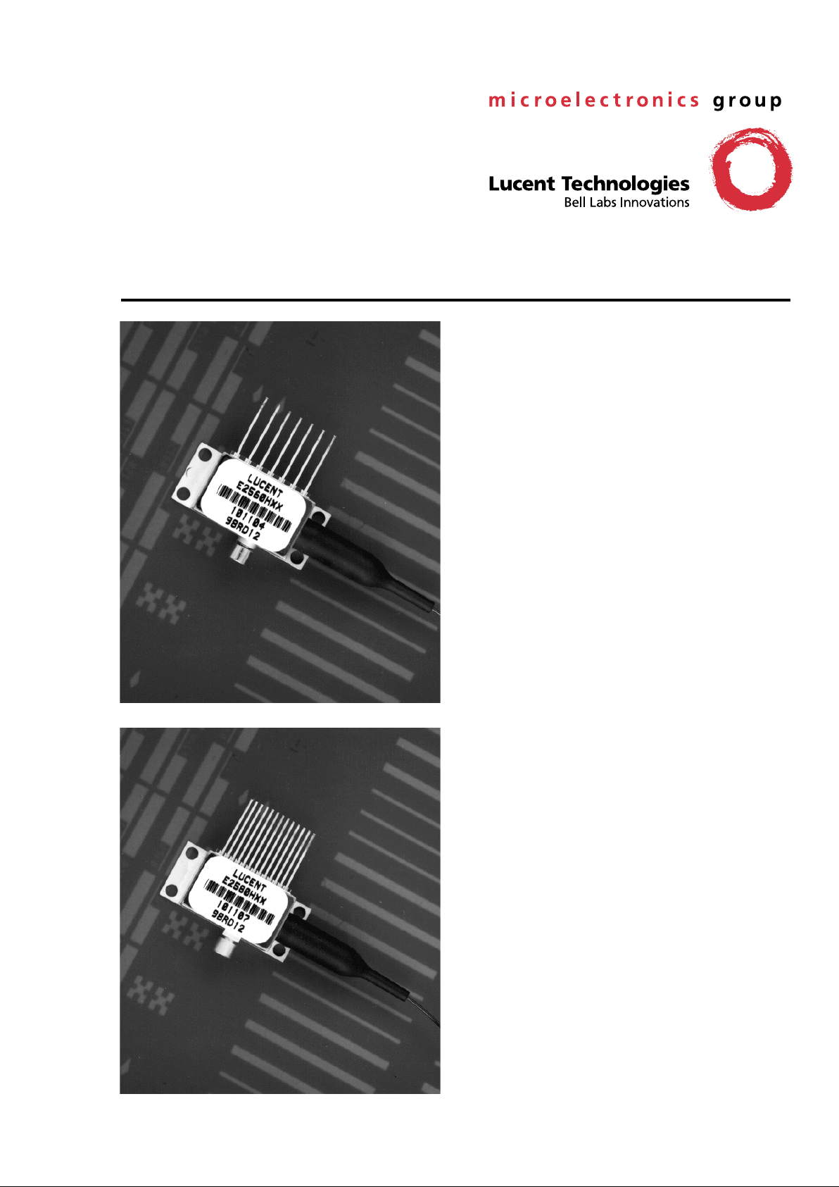
The E2560 (without integral driver IC) and E2580
(with integral driver IC) are devices for 10 Gbits/s
DWDM or TDM transmission applications, which integrate a CW laser with an electroabsorptive modulator
in the same semiconductor chip, and are an extension of Lucent Technologies Microelectronics
Groups’ existing E2500 series of devices. Both types
use a small-profile Gilbert GPO connector to handle
the RF signal. The device is typically coupled with a
number of erbium-doped fiber amplifiers, such as
Lucent Technologies' 1724-series, in order to ensure
that sufficient optical power reaches the receiver.
These devices can replace external modulators
which are often bulkier, more expensive, and require
more complex drive electronics than the EML. Both
E2560 and E2580 are available for transmission distances of 40 km and 80 km. The package also contains a thermoelectric cooler, thermistor, rear facet
monitor photodiode, and an optical isolator.
Page 2
Advance Data Sheet
E2560/E2580-Type 10 Gbits/s EML Modules January 1999
2 Lucent Technologies Inc.
Description
(continued)
The nominal input impedance of the E2560 version is 50 Ω. The package is qualified to the Bellcore TA-TSY-
000468 standard.
Both E2560 and E2580 are available in a range of ITU-T wavelengths for use in D WDM systems operating at 10
Gbits/s per channel. The device has excellent wavelength stability , supporting operation at 100 GHz channel spacing over 20 years (assuming an end-of-life aging condition of <±100 pm). Typically, no external wavelength stabilization is required in systems of this type, using Lucent's E2500 series EMLs. The package also offers excellent
stability of wavelength vs. case temperature, with a maximum coefficient of 0.5 pm/°C.
Module Characteristics
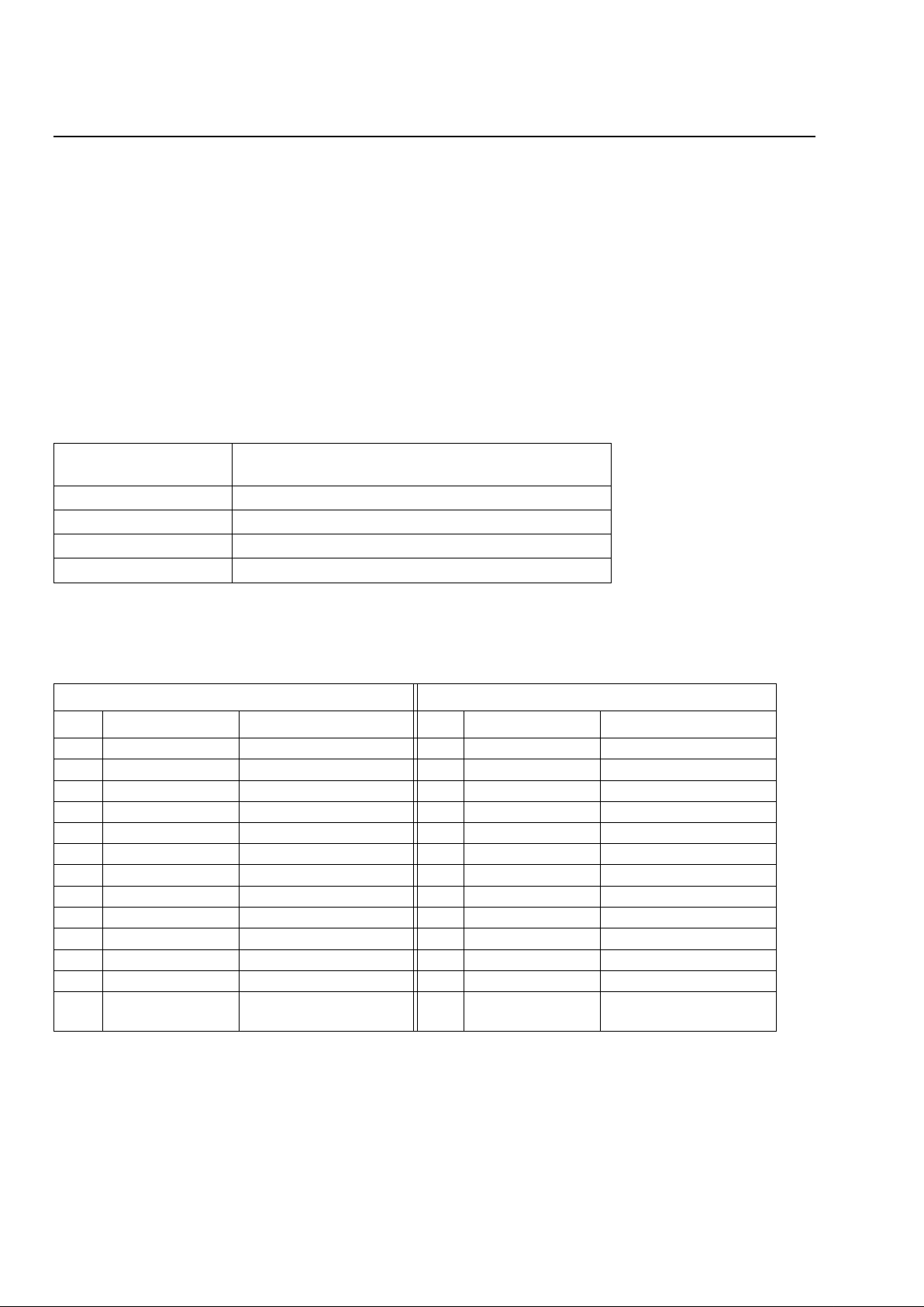
Table 1. Module Characteristics
Pin Information
Table 2. Pin Descriptions
Note: For full details o f pin functions and required bias levels for the version with the IC, refer to
E2580 EML with Integral Driver IC: Pin
Definitions And Operation
Application Note (TBD):
Package Type E2560: 7-pin package with GPO connector RF input.
E2580: 13-pin package with GPO connector RF input.
Fiber Standard single-mode fibe r.
Connector
ST
®
; other connectors available on request.
RF Input Impedance 50 Ω.
Bit Rate 10 Gbits/s.
E2560 E2580
Pin Abbreviation Definition Pin Abbreviation Definition
— — — 13 TEC– Themoelectric cooler–
— — — 12 TEC+ Thermoelectric cooler+
—— — 11V
SS
Voltage supply to the IC
— — — 10 DCA Duty cycle adjust
— — — 9 OA Optical amplitude adjust
— — — 8 NC No connect/reserved
7 TEC– Themoelectric cooler– 7 NC No connect/reserved
6 TEC+ Thermoelectric cooler+ 6 VEA Modular offset (on-state)
5 BACK DET+ Monitor cathode (+) 5 BACK DET+ Monitor cathode (+)
4 BACK DET– Monitor anode (–) 4 BACK DET– Monitor anode (–)
3 LASER+ Laser anode 3 LASER+ Laser anode
2 THERM Thermistor 2 THERM Thermistor
1 THERM, LASER–,
CASE
Combined thermistor/
laser cathode/case
1 THERM, LASER–,
CASE
Combined thermistor/
laser cathode/case
Page 3
Lucent Technologies Inc. 3
Advance Data Sheet
January 1999 E2560/E2580-Type 10 Gbits/s EML Modules
Target Specifications
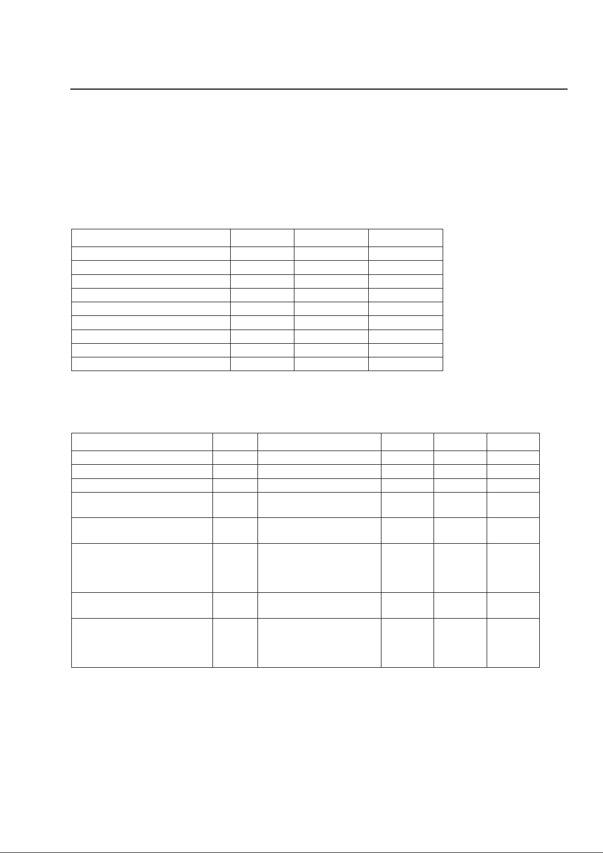
Absolute Maximum Ratings
Stresses in excess of the absolute maximum ratings can cause permanent damage to the device. These are
absolute stress ratings only. Functional operation of the device is not implied at these or any other conditions in
excess of those given in the operational sections of the data sheet. Exposure to absolute maximum ratings for
extended periods can adversely affect device reliability.
Table 3. Absolute Maximum Ratings
Characteristics
Table 4. Optical and Electrical Specifications
(Chip operating temp. = 15 °C to 35 °C, except where noted.)
Parameter Conditions Limit Unit
Laser Diode Reverse Voltage CW 2 V
Laser Diode Forward Current CW 150 mA
Optical Output Power CW 10 mW
Modulator Reverse Voltage — 5 V
Modulator Forward Voltage — 1 V
Monitor Diode Reverse Voltage — 10 V
Monitor Diode Forward Voltage — 1 V
Storage Temperature — –40 to +85 °C
Operating Temperature — –10 to +70 °C
Parameter Symbol Conditions Min Max Unit
Threshold Current (BOL) I
th
— 5 35 mA
Forward Voltage V
F
If = I
op
@ T
op
—2.2V
Operating Current I
op
— 50 100 mA
Threshold Power P
th
If – I
th
Vm = I
op
—80µW
Fiber Output Power (Peak) P
pk
Vm = 0 V
If = I
op
1—dBm
Peak Wavel ength
(Wavelength can be specified
to the ITU wavelength
channels.)
λ0 V
m
= 0 V
T
laser chip
= T
op
If = I
op
1530 1563 nm
Side-mode Suppression Ratio SMSR V
m
= 0 V
If = I
op, Top
30 — dB
Dispersion Penalty
BER = 10
–10
DP 10 Gbits/s*
V
low
= –1.5 to –3.0 V,
V
high
= 0 V to –1 V
If = l
op
@ T
op
—2.0dB
* Over 720 ps/nm (40 km ver sion), 1440 ps/nm (80 km version).
Page 4

Advance Data Sheet
E2560/E2580-Type 10 Gbits/s EML Modules January 1999
4 Lucent Technologies Inc.
* Over 720 ps/nm (40 km version), 1440 ps/nm (80 km version).
†T
case
= 70 °C, T
laser chip
= 15 °C to 35 °C (E2560), 20 °C to 35 °C (E2580).
Modulator/Driver
Extinction Ratio ER
RF
Vin = 0.5 Vp-p to 1.0 Vp-p
10 Gbits/s (E2580)
V
m
= 0 V to –2.5 V
10 Gbits/s (E2560)
11 — dB
RF Return Loss (E2560)
(0 GHz to 6 GHz)
S
11
Vm = –1 V
If = I
op
10 — dB
RF Return Loss (E2560)
(6 GHz to 8 GHz)
S
11
Vm = –1 V
If = I
op
7—dB
RF Return Loss (E2560)
(8 GHz to 10 GHz)
S
11
Vm = –1 V
If = I
op
5—dB
–3 dB Bandwidth (E2560) BW V
m
= –1 V
If = I
op
11 — GHz
RF Return Loss (E2560)
(0 GHz to 10 GHz)
S
11
Vin = 0.5 Vp-p to 1.0 Vp-p
10 Gbits/s
10 — dB
Input Voltage (E2580)
(Peak to Peak)
(ac coupled input)
V
IN
—0.51.0V
Rise/Fall Time
(20%—80%)
tr/tf — — 40 ps
Monitor Diode
Monitor Current I
bd
V
bd
= 5 V
I
f
= I
op
40 1100
µ
A
Dark Current I
d
Vbd = 5 V — 0.1
µ
A
Capacitance C V
bd
= 5 V
f = 1 MHz
—25pF
Thermistor
Resistance R
therm
T = 25 °C 9.5 10.5 k
Ω
Thermistor Curr ent I
tc
—10100
µ
A
Thermistor B Constant B — 3700 4100 —
Thermoelectric Cooler
TEC Current I
TEC
†
—1.1A
TEC Voltage V
TEC
†
—2.6V
TEC Power P
TEC
†
—2.9W
TEC Capacity
∆
T
†
55 — C
Optical Isolation
Optical Isolation —
†
30 — dB
Package
Wavelength vs. Case Temp. dλ/ dT T
case
= –10 °C to 70 °C— 0.5pm/
°
C
Parameter Symbol Conditions Min Max Unit
Target Specifications
(continued)
Table 4. Optical and Electrical Specifications
(Chip operating temp. = 15 °C to 35 °C, except
where noted.)(continued)
Page 5
Lucent Technologies Inc. 5
Advance Data Sheet
January 1999 E2560/E2580-Type 10 Gbits/s EML Modules
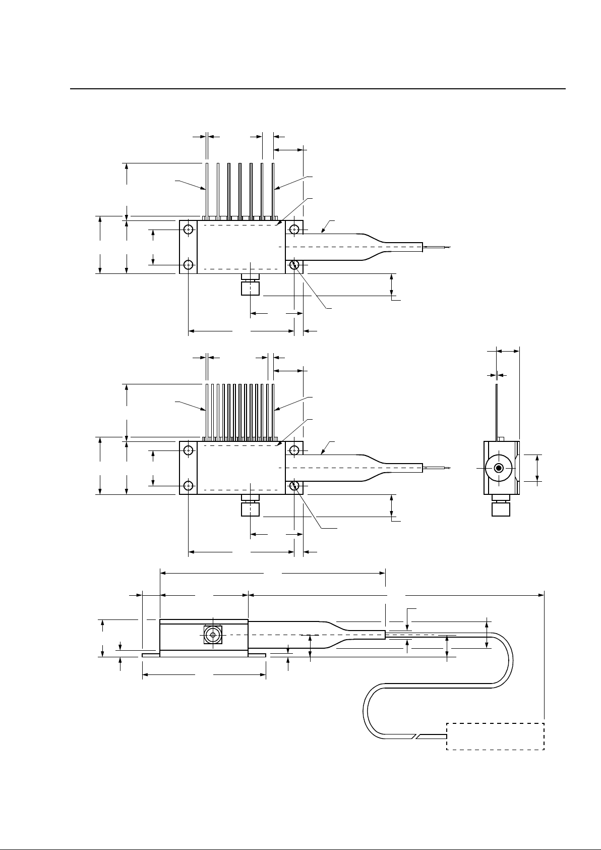
Outline Diagram
1-1006(F).r1
0.291
(7.38)
0.215
(5.47)
0.291
(7.384)
0.100
(2.54)
0.020
(0.508)
0.350
(8.89)
0.500
(12.7)
0.551
(13.99)
0.50
(12.7)
LEAD 7
LEAD 1
TRADEMARK CODE LASER SERIAL NUMBER
AND DATE CODE LABEL IN AREA SHOWN
BEND LIMITER
0.498
(12.64)
1.025
(26.04)
∅
0.106
(2.7)
0.190
(4.822)
E2560:
0.078
(1.98)
0.050
(1.27)
0.020
(0.51)
0.350
(8.89)
0.500
(12.7)
0.551
(13.99)
50
(12.7)
LEAD 13
LEAD 1
TRADEMARK CODE LASER SERIAL NUMBER
AND DATE CODE LABEL IN AREA SHOWN
BEND LIMITER
0.498
(12.64)
1.025
(26.04)
∅
0.106
(2.7)
0.190
(4.82)
E2580:
12 PLACES
CONNECTOR TYPE
AS SPECIFIED
1.180
(29.97)
2.032
(51.61)
0.820
(20.83)
TBD
0.56
(1.42)
0.365
(9.27)
0.180
(4.56)
0.030
(0.75)
0.228
(5.78)
0.98
(2.5)
0.260
(6.6)
0.200
(5.08)
0.078
(1.98)
0.010 ± 0.002
(0.25 ± 0.064)
MIN
3 PLACES
4 PLACES
PLACES
0.215
(5.45)
Page 6

Advance Data Sheet
E2560/E2580-Type 10 Gbits/s EML Modules January 1999
For additional information, contact your Microelectronics Group Account Manager or the following:
INTERNET:
http://www.lucent.com/micro
, or for Optoelectronics information,
http://www.lucent.com/micro/opto
E-MAIL:
N. AMERICA: Microelectronics Group, Lucent Technologies In c., 555 U nion Boulevard, Room 30L-15P-BA, Allentown, PA 18103
1-800-372-2447
, FAX 610-712-4106 (In CANADA:
1-800-553-2448
, FAX 610-712-4106)
ASIA PACIFIC:Microelectronics Group, Lucent Technologies Singapore Pte. Ltd ., 77 Science Park Drive, #03-18 Cintech III, Singapore 118256
Tel. (65) 778 8833
, FAX (65) 777 7495
CHINA: Microelectronics Group, Lucent Technologies (China) Co., Ltd., A-F2, 23/F, Zao Fong Universe Building, 1800 Zhong Shan Xi Road,
Shanghai 200233 P. R. China
Tel. (86) 21 6440 0468, ext. 316
, FAX (86) 21 6440 0652
JAPAN: Microelectronics Group, Lucent Technologies Japan Ltd., 7-18, Higashi-Gotanda 2-chome, Shinagawa-ku, Tokyo 141, Japan
Tel. (81) 3 5421 1600
, FAX (81) 3 5421 1700
EUROPE: Data Requests: MICROELECTRONICS GROUP DATALINE:
Tel. (44) 1189 324 299
, FAX (44) 1189 328 148
Technical Inquiries:OPTOELECTRONICS MARKETING:
(44) 1344 865 900
(Ascot UK)
Lucent Technologies Inc. reserves the right to make changes to the product(s) or information contained herein without notice. No liability is assumed as a result of their use or application. No
rights under any patent accompany the sale of any such product(s) or information. ST is a registered trademark of Lucent Technologies Inc.
Copyright © 1999 Lucent Technologies Inc.
All Rights Reserved
January 1999
DS99-078LWP
Printed On
Recycled Paper
Laser Safety Information
Class IIIb Laser Product
This product complies with 21 CFR 1040.10 and 1040.11.
Single-mode connector
Wavelength = 1.5 µm
Maximum power = 10 mW
Because of size constraints, laser safety labeling is not affixed to the module but attached to the outside of the ship-
ping carton.
Product is not shipped with power supply.
Caution
: Use of controls, adjustments, and procedures other than those specified herein may result in hazardous
laser radiation exposure.
 Loading...