

Page 1
Monitoring Relays
3-Phase Load Guard
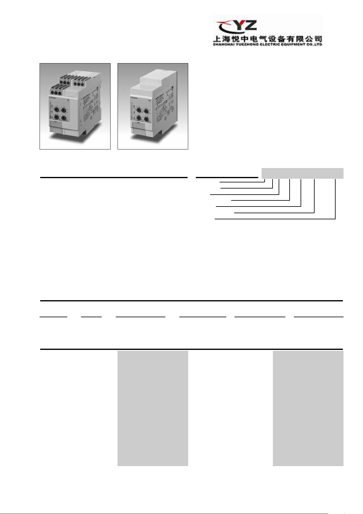
Types DWB01, PWB01
DWB01 PWB01
• TRMS load guard relays for three phase
alanced applications
b
• Measuring if the power factor is within set limits
• Measure voltage on own power supply
• Measuring ranges: 5A, 10A, MI current transformers
• Power ON delay 1 to 30 s knob adjustable
• Separately adjustable upper/lower level on absolute
scale
• Programmable latching or inhibit at set level
• Automatic and manual start and stop of the system
Output: 8 A SPDT relay N.D. or N.E. selectable
•
• For mounting on DIN-rail in accordance with DIN/EN
50 022 (DWB01) or plug-in module (PWB01)
• 45 mm Euronorm housing (DWB01) or 36 mm plug-in
module (PWB01)
• LED indication for relay, alarm and power supply ON
Product Description
DWB01 and PWB01 are
precise TRMS power factor
monitoring relays for 3phase balanced systems.
They can be used for monitoring the actual load of
asynchronous motors and
other symmetrical loads,
where the power factor is
almost proportional to the
load.
The relay measures the
power factor (cos
the ratio between the active
and the apparent power of a
motor.
ϕ), that is
Start/stop input allows to
use a manual switch to start
and stop the motor, without
the need of an auxiliary
device.
The advantage of using the
latch function is that the
relay can be kept energized
even after the end of the
alarm condition. Inhibit function can be used to avoid
relay operation when not
desired (maintenance, transients).
The LED's indicate the state
of the alarm and the output
relay.
Ordering key
Housing
Function
Type
Item number
Output
Power Supply
Range
DWB 01 C M48 10A
Type Selection
Mounting Output Supply: Supply: Supply: Supply:
DIN-rail
Plug-in
SPDT
SPDT
208 to 240 VAC 380 to 415 VAC 380 to 480 VAC 600 to 690 VAC
DWB 01 C M23 10A
PWB 01 C M23 10A
PWB 01 C M48 10A
DWB 01 C M48 10A DWB01 C M69 10A
Input Specifications
Input
V
oltage
(Own power supply):
3 - phase DWB01: L1, L2, L3
1- phase DWB01CM23: L1, L2 (connect pins L2, L3)
ent: DWB01: 5A, 10A: I1, I2
Curr
PWB01:
M23: 208 to 240 VAC ± 15%
DWB01CM48: 380 to 480 VAC ± 15%
PWB01CM48: 380 to 415 VAC ± 15%
DWB01CM69: 600 to 690 VAC ± 15%
PWB01CM23:
PWB01:
5, 6, 7
5, 6 (connect pins 6, 7)
208 to 240 VAC ± 15%
MI...: U1, U2
5A, 10A:
MI...:
11, 10
9, 8
Measuring ranges Upper level Lower level
Power factor (cos ϕ) 0.1 to 0.99
AACrms Max. curr.
Direct input: 0.5 to 5A 30A
Standar
TADK2 50 A/5 A 5 to 50 A 60 A
TAD2 150 A/5 A 15 to 150 A 180 A
T
T
TACO200 6000 A/5 A 600 to 6000 A 7200 A
MI CT ranges
MI 100
MI 500
d CT (examples)
AD6 400 A/5 A 40 to 400 A
AD12 1000 A/5 A
1 to 10A 50A
100 to 1000 A 1200 A
10 to 100 A
50 to 500 A
0.1 to 0.99
(30 s)
480 A
325 AAC
1000 AAC
1
Page 2

WB01, PWB01
D
Input Specifications (cont.)
Note:
The input voltage cannot
raise over 300 VAC with
respect to ground (PWB01
only)
Contact input
DWB01 Terminals Z1, U1
PWB01 Terminals 2, 9
Disabled > 10 kΩ
Enabled < 500 Ω
Pulse width > 500 ms
Hysteresis PF approx 0.1
Power ON delay 1 to 30 s ± 0.5 s
Reaction time (input signal variation from
Alarm ON delay < 200 ms
Alarm OFF delay < 200 ms
Accuracy (15 min warm-up time)
Temperature drift ± 1000 ppm/°C
Delay ON alarm ± 10% on set value ± 50 ms
Repeatability ± 0.5% on full-scale
Indication for
Power supply ON LED, green
Alarm ON LED, red (flashing 2 Hz
Output relay ON LED, yellow
Environment
ee of protection IP 20
Degr
Pollution degr
Operating temperature
@ Max. voltage, 50 Hz -20 to 60°C, R.H. < 95%
@ Max. voltage, 60 Hz -20 to 50°C, R.H. < 95%
Storage temperature -30 to 80°C, R.H. < 95%
Housing dimensions
DIN-rail version 45 x 80 x 99.5 mm
Plug-in version 36 x 80 x 94 mm
W
eight
ew ter
Scr
Tightening torque Max. 0.5 Nm
ovals
Appr
CE-Marking Y
EMC Electromagnetic Compatibility
Immunity According to EN 61000-6-2
Emissions
ee
minals
-20% to +20% or from
+20% to -20% of set value)
during delay time)
3 (DWB01), 2 (PWB01)
Appr
ox. 250 g
acc. to IEC 60947
UL, CSA
es
ding to EN 61000-6-3
Accor
Output Specifications
Output SPDT relay
Rated insulation voltage 250 VAC
Contact ratings (AgSnO
Resistive loads AC 1 8 A @ 250 VAC
Small inductive loads AC 15 2.5 A @ 250 VAC
Mechanical life ≥ 30 x 106operations
Electrical life ≥ 10
Operating frequency ≤ 7200 operations/h
ielectric strength
D
Dielectric voltage ≥ 2 kVAC (RMS)
Rated impulse withstand volt. 4 kV (1.2/50 µs)
)µ
2
DC 12 5 A @ 24 VDC
DC 13 2.5 A @ 24 VDC
5
operations
(at 8 A, 250 V, cos ϕ = 1)
ccording to EN 60947-1
A
Supply SpecificationsGeneral Specifications
Power supply Overvoltage cat. III
Rated operational voltage (IEC 60664, IEC 60038)
Through terminals:
Dielectric voltage None
Dielectric voltage
supply to output 4 kV
Rated operational power
Supplied by L1 and L2
DWB01: L1, L2, L3
PWB01: 5, 6, 7
M23 177 to 276 VAC 45 to 65 Hz
DWB01CM48 323 to 552 VAC45 to 65 Hz
PWB01CM48 323 to 477 VAC 45 to 65 Hz
DWB01CM69 510 to 793 VAC 45 to 65 Hz
M23: 9 VA @ 230 VAC, 50 Hz
M48: 13 VA @ 400 VAC, 50 Hz
M69: 21 VA @ 600 VAC, 50 Hz
Mode of Operation
DWB01 and PWB01 can be
used for monitoring the actual load of asynchronous
motors.
The relay measures the
absolute value for the power
factor of the system PF=
Active Power/Apparent Power that is for balanced system with sinus waveforms
the cosine of the angle
between motor current and
motor voltage (cos
As cos
ϕ varies with the load
of the motor, underload and
overload can be indirectly
detected by DWB01 and
PWB01.
The relation between the
load and cos
the type of motor
ϕ).
ϕ depends on
. As a
guideline to ensure correct
working conditions for a
motor, the upper level could
be set above the cos
marking on the motor, and
the lower level under this val
ue. It is anyway recommended to make the adjustment in
connection with a practical
test. The relay has an
adjustable power ON delay
in order to avoid overload
detection during motor star
Example 1
Latching mode, relay NE
In this application DWB01 or
PWB01 ar
external current metering
transformer, type MI..., (connected between U1 & U2) as
e connected to an
ϕ
-
t.
2
Page 3
WB01, PWB01
L2 L3L1
15
16 18
cos j
cos j
U1
U2
Z1
I2I1
675
1
43
cos j
cos j
9
8
2
1011
D
Mode of Operation (cont.)
utomatic reactivation of the
ell as to a 3-phase asyn-
w
chronous motor. The relay
nergizes as soon as the
e
power supply is applied.
After the power ON delay,
the unit starts measuring cos
ϕ. If cos ϕ is within the setpoints the relay is energized.
As soon as the power factor
rops below the lower set-
d
oint or exceeds the upper
p
etpoint the output relay
s
releases and the red LED
turns on after the set time
has expired. To restart the
cos
ϕ measurement, connect
Z1 and U1 (2 and 9) or interrupt the power supply for at
least 1 s.
Example 2
Non-latching mode, relay NE
DWB01 and PWB01 react as
described in the previous
example 1 except for the
a
elay as soon as cos ϕ i
r
ack within the two set-
b
points. When the measured
cos
ϕ exceeds the set upper
level, the red LED starts
flashing. The output relay
releases after the set time
period. When the measured
os
c
rops below the set
ϕ d
lower level, the red LED
tarts flashing, and the out-
s
put relay releases after the
set time period. When the
output relay releases there
will be no LED indication.
Example 3
1-Phase load monitoring
DWB01CM2310A and
PWB01CM2310A can be
used for monitoring the power factor of a 1-Phase load
with 208 to 240 V AC mains
voltage. In this case the pow-
r supply has to be connect-
e
d between L1, L2 (or 5, 6),
e
s
2 and L3 (or 6 and 7) have
L
to be connected.
Example 4
Start/stop mode, relay NE
In this application DWB01 or
PWB01 are directly connect-
d to a 3-phase asyn-
e
hronous motor. The relay
c
nergizes as soon as the
e
power supply is applied and
the start/stop contact is
closed. After the power ON
delay, the unit starts measuring cos
ϕ. If cos ϕ is within
the setpoints the relay energizes. As soon as the power
factor drops below the lower
setpoint or exceeds the
upper setpoint the output
relay releases and the red
LED turns ON after the set
time has expired. When the
tart/stop contact is opened
s
he relay de-energizes imme-
t
iately. To restart the system
d
just connect the start/stop
contact.
Note 1: to use the start/stop
function the output relay has
o command a contactor
t
onnected in series to the
c
oad (see last two wiring dia-
l
grams).
Note 2: in case of current
below the minimum level the
alarm is conventionally ON.
Note 3: (3-phase voltage):
connect the 3-phase power
supply to the terminals L1,
L2 and L3 (DWB01) - 5, 6
and 7 (PWB01) taking care of
the sequence.
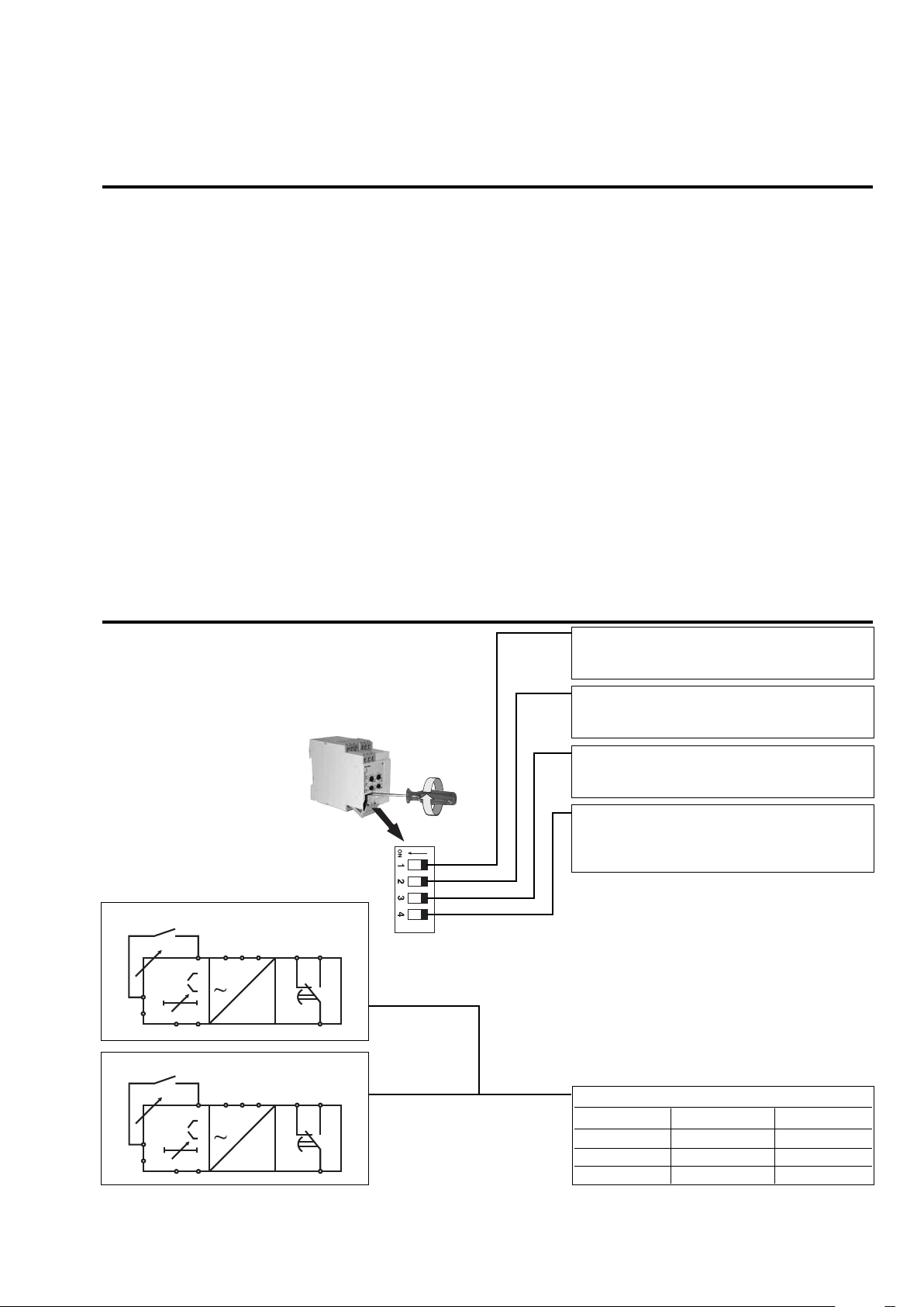
Function/Range/Level/Time Setting
Select the desired function
setting the DIP-switches 1
to 4 as shown on the right.
To access the DIP-switches
open the plastic cover using
a screwdriver as shown on
the right.
If DIP switch 3 is set to ON
(start/stop) the position of
DIP-switch 4 does not affect
oducts working mode.
the pr
Centre knobs:
Setting of upper and lower
level of cos
ϕ 0.1 to 0.99.
DWB01
Contact input
PWB01
Contact input
Lower left knob:
Setting of delay on absolute
scale: 0.1 to 30 s.
Lower right knob:
Setting of power ON delay
on absolute scale: 1 to 30 s.
Input current range (terminals I1, I2 or 10, 11)
ON: 10A
OFF: 5A/MI input
Relay status
ON: Relay de-energized in normal condition
OFF: Relay energized in normal condition
Working mode
ON: Contact input for start/stop functions
OFF: Contact input for latch/inhibit functions
Contact input (SW4 does not affect the
working mode if SW3 is ON)
ON: Latch function enable
Inhibit function enable
OFF:
Notes
1.
DIP-switch 3 set ON enables the start/stop
function that is managed by the closingopening of the contact input.
2.DIP-switch 3 set OFF enables the input
contact for the latch/inhibit functions: the
selection between these is allows by the DIP
switch 4.
The following table shows how the input con
tact manages the mode of operation:
Contact input working mode
OPEN
ACTIVE
LA
TCH
CLOSED
NOT ACTIVE
INHIBIT ACTIVE NOT ACTIVE
START/STOP START STOP
-
3
Page 4
WB01, PWB01
L2 L3L1
N
L
m
15
16 18
U1
U2
Z1
I2I1
cos j
cos j
675
N
L
m
1
43
9
8
2
1011
cos j
cos j
L2 L3L1
L1
L2
L3
m
15
16 18
Grey
U1
U2
Z1
I2I1
cos j
cos j
675
L1
L2
L3
m
1
43
Grey
9
8
2
1011
cos j
cos j
L
2L3L1
L1
L2
L
3
m
1
5
1
618
U1
U2
Z
1
I2I1
cos j
cos j
I1
675
L
1
L2
L3
m
1
43
9
8
2
1011
cos j
c
os j
I1
L2 L3L1
L1
L2
L3
m
1
5
16 18
I1
cos j
cos j
U1
U2
Z1
I2I1
675
L
1
L2
L3
m
1
43
I1
c
os j
cos j
9
8
2
1
011
D
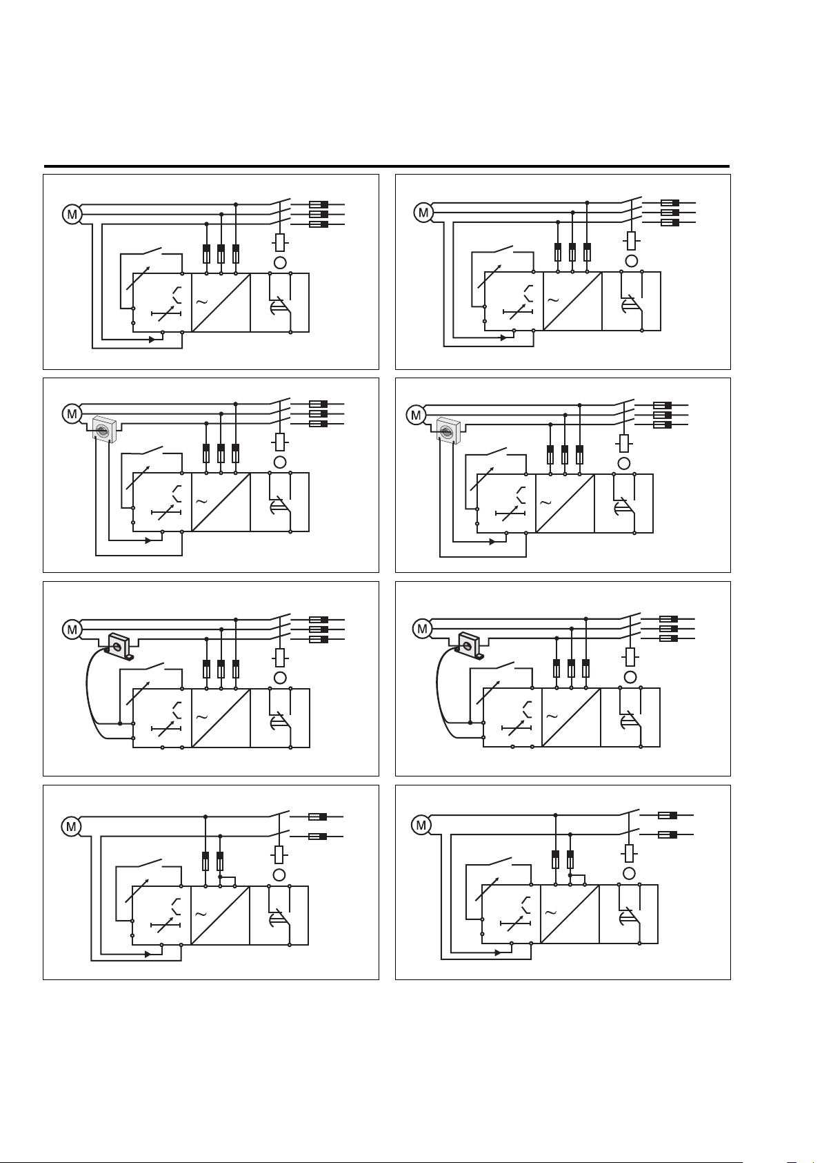
Wiring Diagrams
DWB01 - Direct connection PWB01 - Direct connection
L
atch/Inhibit
Contact
DWB01 - Standard CT PWB01 - Standard CT
L
atch/Inhibit
Contact
L
atch/Inhibit
Contact
Latch/Inhibit
C
ontact
DWB01 - MI CT PWB01 - MI CT
Latch/Inhibit
Contact
PWB01CM2310A - Direct connection - 1-Phase LoadDWB01CM2310A - Direct connection - 1-Phase Load
Latch/Inhibit
Contact
Latch/Inhibit
Contact
Latch/Inhibit
Contact
4
Page 5

T T T
L
2L3L1
m
15
1
618
L
1
L2
L3
c
os j
cos j
U1
U
2
Z
1
I
2I1
I
1
N
675
m
1
43
L
1
L2
L3
c
os j
c
os j
9
8
2
1
011
I
1
N
WB01, PWB01
T T
D
Wiring Diagrams (cont.)
With the start/stop function enabled, it’s necessary to use the following wiring diagrams (which are two examples among
many others). It is possible for both 3-phase loads and 1-phase loads, either through direct connection or external current
metering transformer.
WB01 - Direct connection - Manual start and stop (NE relay)
D
WB01 - Direct connection - Manual start and stop (NE relay)
P
Start/stop
C
ontact
Operation Diagrams
Latch function - NE relay
Power supply
Latch contact
(Closed = latch not active)
Upper Level
Hysteresys
Lower Level
Relay ON
Hysteresys
Power
ON
Power
ON
Start/stop
C
ontact
Inhibit function - ND relay
Power supply
Inhibit contact
(Closed = inhibit active)
Upper Level
Hysteresys
esys
Lower Level
Relay ON
Hyster
Power
ON
Start and stop function - NE relay
Power supply
t/Stop contact
Star
(Closed = Star
Upper Level
Lower Level
Relay ON
t; Open = Stop)
Hysteresys
Hyster
esys
Power
ON
Power
ON
5
Page 6
WB01, PWB01
45
80
83.5
9
9.5
63
28.5
36
80
94
2
8.5
63
90
D
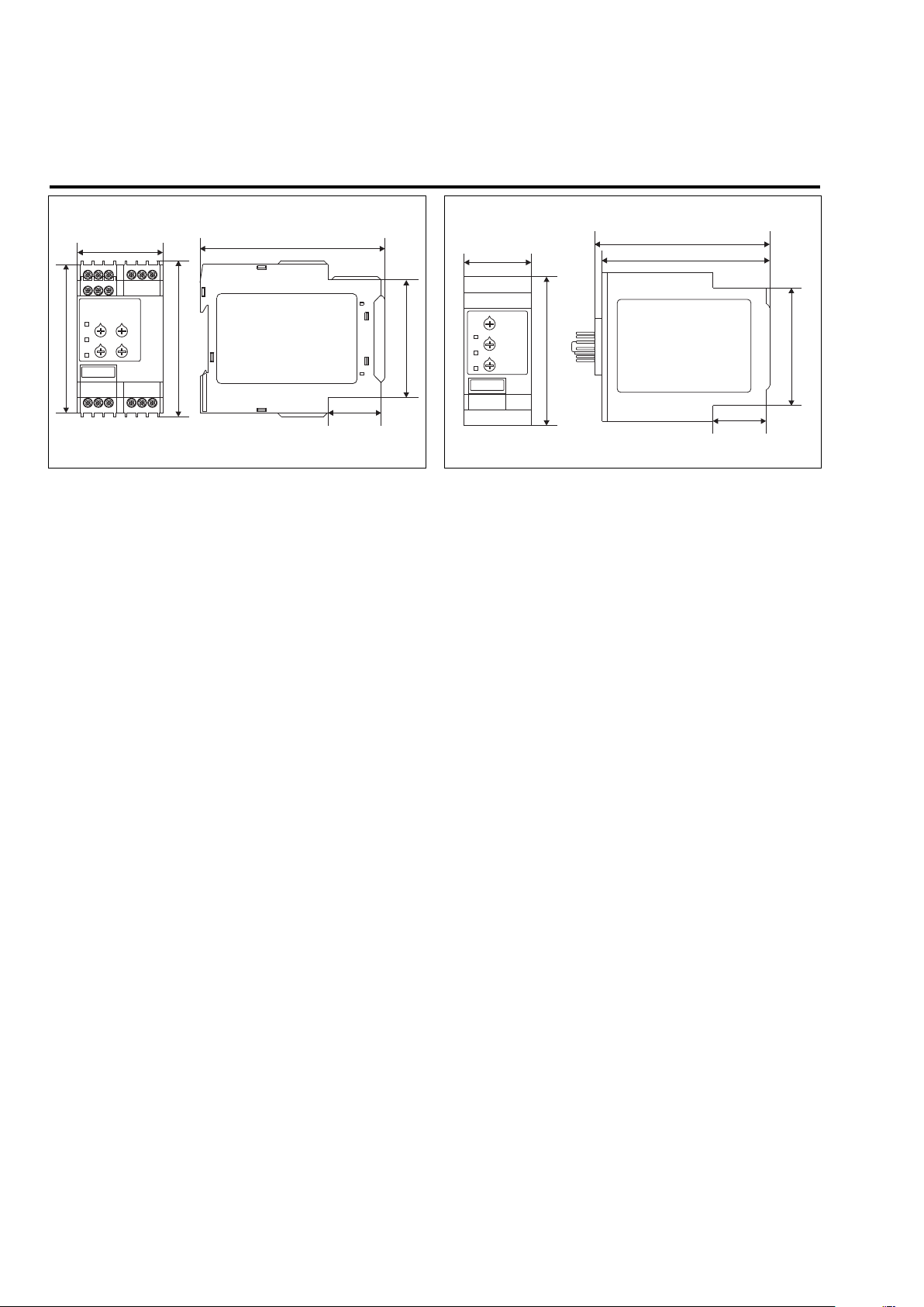
Dimensions
Plug-inDIN-rail
6
 Loading...