

Page 1
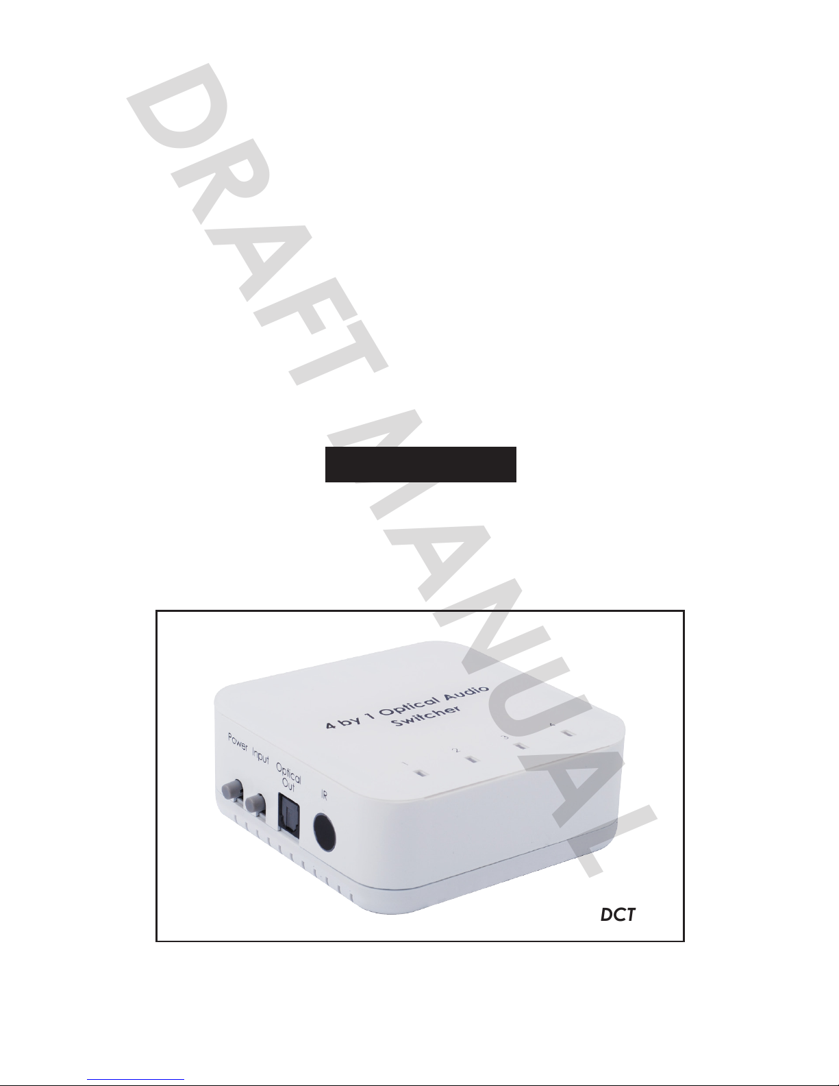
DCT-17
4 by 1 Optical Audio
Switcher with IR Remote
Operation Manual
DCT-17
DRAFT MANUAL
Page 2

Disclaimers
The information in this manual has been carefully checked and
is believed to be accurate. Cypress Technology assumes no
responsibility for any infringements of patents or other rights of third
parties which may result from its use.
Cypress Technology assumes no responsibility for any inaccuracies
that may be contained in this document. Cypress also makes
no commitment to update or to keep current the information
contained in this document.
Cypress Technology reserves the right to make improvements to this
document and/or product at any time and without notice.
Copyright Notice
No part of this document may be reproduced, transmitted,
transcribed, stored in a retrieval system, or any of its part translated
into any language or computer le, in any form or by any means
- electronic, mechanical, magnetic, optical, chemical, manual,
or otherwise - without express written permission and consent from
Cypress Technology.
© Copyright 2010 by Cypress Technology.
All Rights Reserved.
Version 1.0 August 2010
Trademark Acknowledgments
All products or service names mentioned in this document may be
trademarks of the companies with which they are associated.
Page 3

Safety Precautions
Please read all instructions before attempting to unpack or install or
operate this equipment, and before connecting the power supply.
Please keep the following in mind as you unpack and install this
equipment:
Always follow basic safety precautions to reduce the risk of
re, electrical shock and injury to persons.
To prevent re or shock hazard, do not expose the unit to rain,
moisture or install this product near water.
Never spill liquid of any kind on or into this product.
Never push an object of any kind into this product through
module openings or empty slots, as you may damage parts.
Do not attach the power supply cabling to building surfaces.
Do not allow anything to rest on the power cabling or allow it to
be abused by persons walking on it.
To protect the equipment from overheating, do not block the
slots and openings in the module housing that provide ventilation.
Revision History
Version No Date Summary of Change
V1 20100802 Preliminary Release
VR2 20110119 5.1 Output Level
Page 4

Table of Contents
1. Introduction..................................................................................1
2. Applications................................................................................. 1
3. PackageContents......................................................................1
4. Features........................................................................................1
5. Specifications..............................................................................2
5.1 Input Audio Reference Level ..................................... 2
6. OperationControlsandFunctions............................................. 3
6.1 Top Panel ...................................................................... 3
6.2 Left ................................................................................. 3
6.3 Right Panel ................................................................... 4
6.4 Rear Panel .................................................................... 4
7. RemoteControl............................................................................5
8. ConnectionandInstallation...................................................... 5
9. Acronyms..................................................................................... 6
Page 5

1
1. Introduction
The 4 by 1 Optical Audio Switcher is a device with four optical inputs and one
optical output. This device allows users with multiple optical sources to connect
for one output display while all signals can bypass without delay.
The device has a built in last memory function and IR remote control which
provides a more users friendly operating experience.
2. Applications
• Multi-selection audio performance
• Optical audio signal display
• Theater performance
• Audio showroom control
3. Package Contents
• 4 by 1 Optical Audio Switcher
• IR Remote Control (CR-72)
• 5V / 1A Power Adaptor
• Operation Manual
4. Features
• Optical sampling rate supports up to 192 kHz
• Low power consumption
• up to 24 bit resolution
Page 6

2
5. Specications
Input Ports 4 x Optical
Sample Frequency Up to 192 kHz
Output Port 1 x Optical
Audio Format PCM2, Dolby 5.1 & DTS 5.1 pass through
Power Supply 5V / 1A DC ( US/EU standards, CE/FCC/UL certied)
ESD Protection Human body model: ± 8kV (air-gap discharge)
± 6kV (contact discharge)
Dimensions(mm) 100 (W) x 70 (D) x 20(H)
Weight(g) 90
Chassis Material Plastic
Silkscreen Color Black
Operating Temperature 0°C~40°C / 32°F~104°F
Storage Temperature -20°C~60°C / -4°F~140°F
Power Consumption <1W
Relative Humidity 20 ~ 90% RH (non-condensing)
5.1InputAudioReferenceLevel
Input Level /
Frequency
Output
Terminal
Output
Level
THD+N
Frequence
Response
SNR Crosstalk
Optical
0dBFS 1kHz
Optical 0~0.05dBFS <0.01% ±1dBFs >90dB <-90dB
Page 7
3
6. Operation Controls and Functions
6.1TopPanel
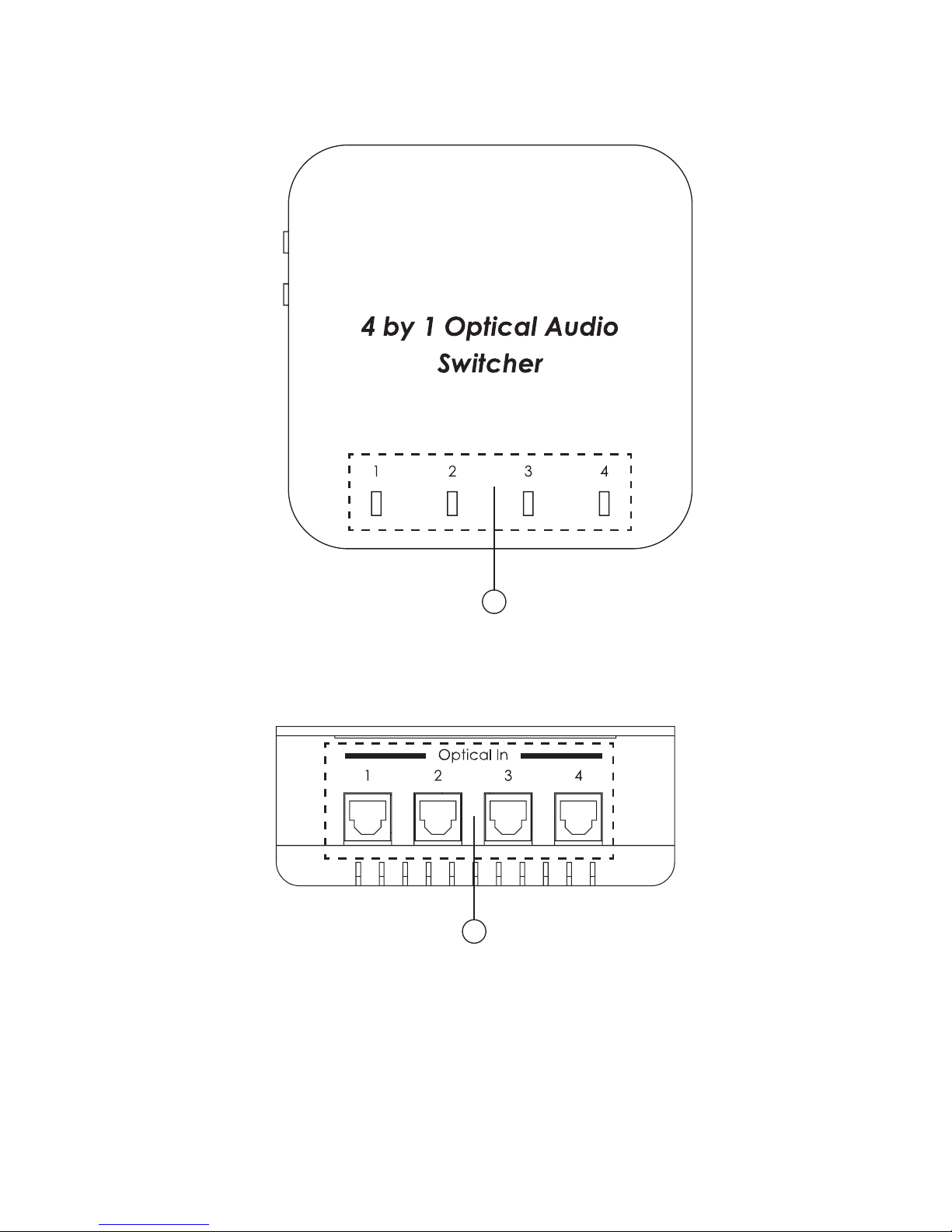
1
①
Input 1~4: The LED will illuminate in blue when selected the source.
6.2LeftPanel
1
1
Optical In: These slots are to connect with input source equipments such
as DVD/Blue-Ray player for audio input signal sending.
Page 8
4
6.3RightPanel
1 2 3 4
①
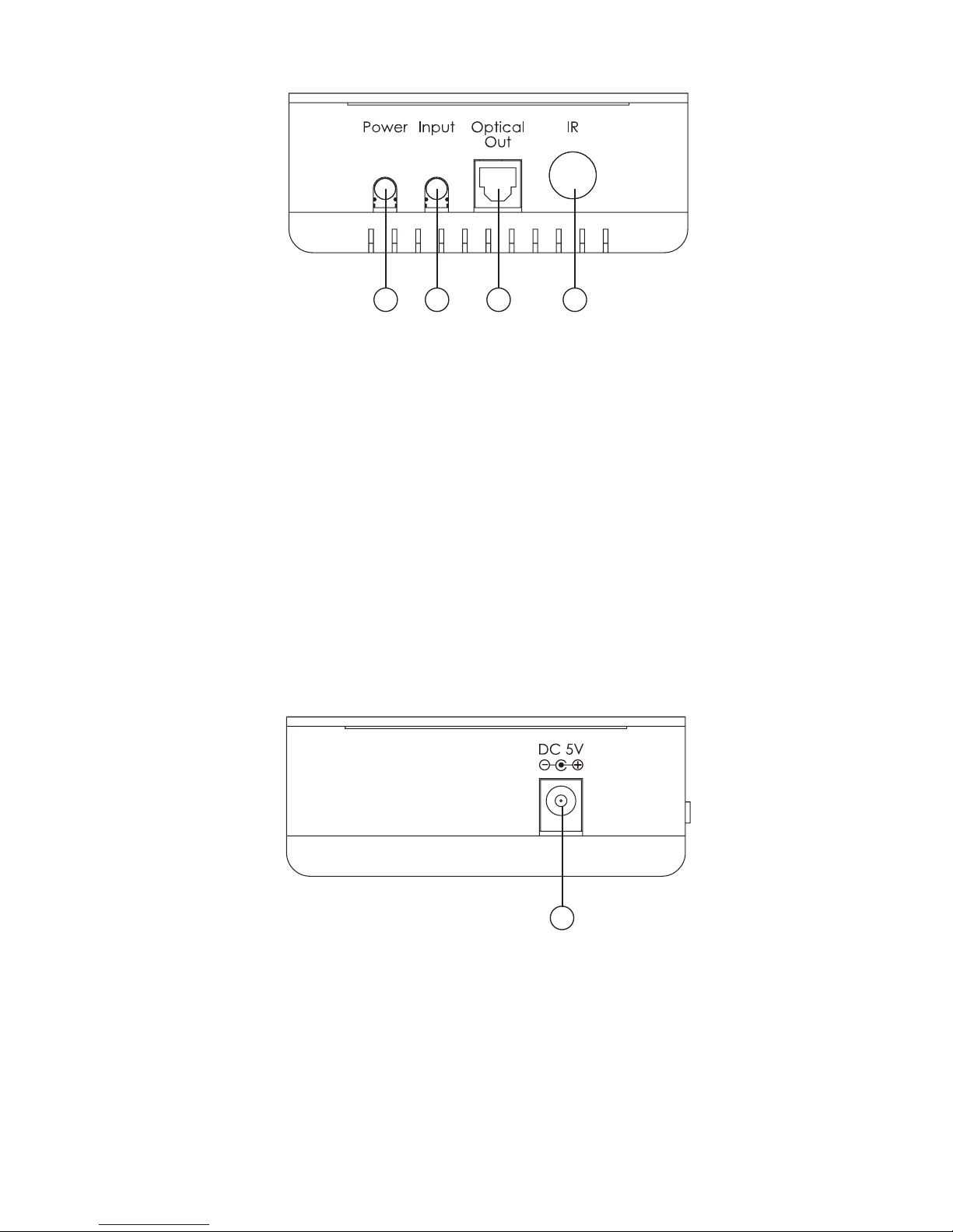
Power: Press this button to turn on the device or to set it to standby
mode. The blue LED on the top panel will illuminate when the device is
turn on.
②
Input: Press this button to select the input port from 1~4. The blue LED on
the top panel will illuminate according to the selection.
③
Optical OUT: This slot is where you connect the amplier or active
speaker with optical cable for audio output.
④
IR: This is the IR receiver window receiving IR signal from the remote
control included with the device.
6.4RearPanel
1
①
DC 5V: This slot is where you plug the 5V DC power supply into the unit
and connect the adaptor to an AC wall outlet.
Page 9
5
7. Remote Control
1
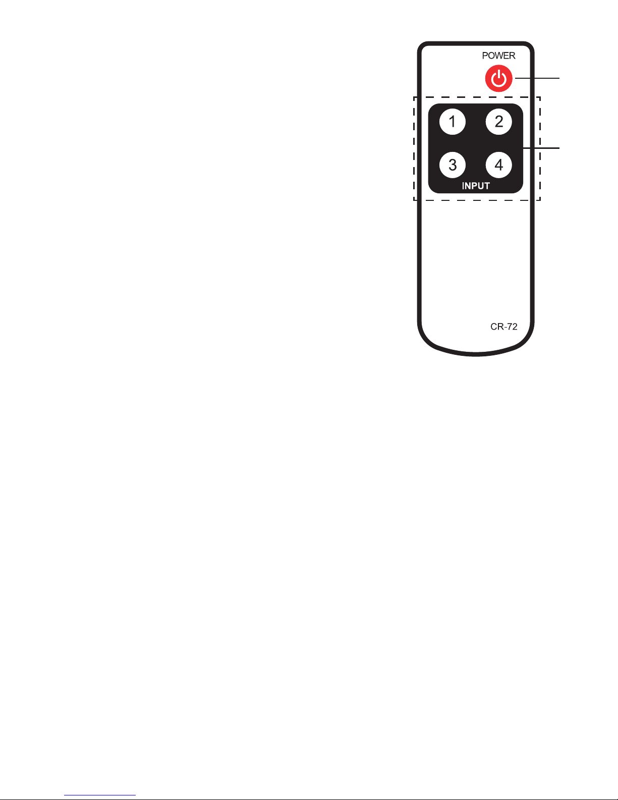
Power button: Press to switch On the
device,press it again to set the device in
standby mode.
②
1~4: Press the desire input button to select
the input source.
1
②
Page 10
6
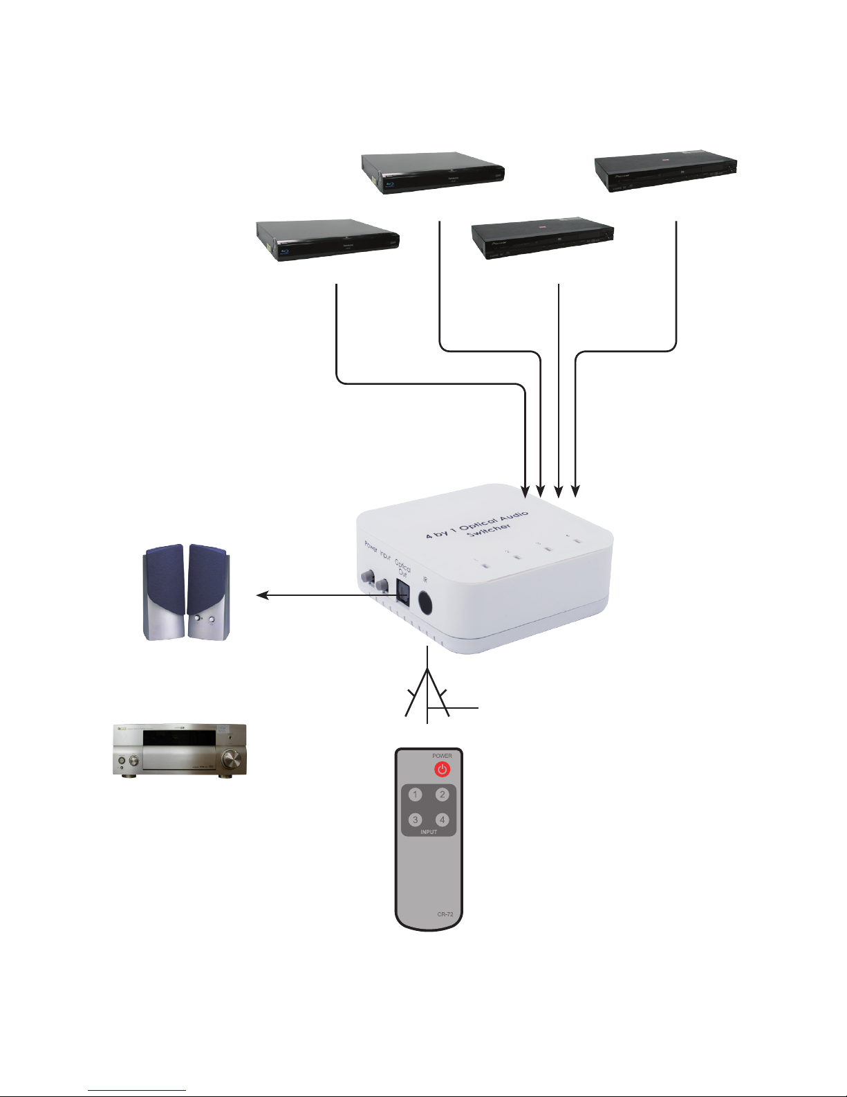
7. Connection and Installation
DVD
DVD
Blu-ray
Blu-ray
Amplier
Active Speaker
or
30˚
30˚
3
M
7
M
3
M
Page 11

7
Acronyms
A
Acronym Complete Term
Page 12

MPM-DCT17
Home page: http://www.cypress.com.tw
CYPRESSTECHNOLOGYCO.,LTD.
 Loading...