

Page 1
82 [3.228]
Communication
Message type I/O polling; explicit
1
is
H2 is the same
download the configured data to the master and
H2 is consistent
on the network is
1. Check if the network cable is correctly connected to
9
82 [3.228]
1
2
3
4
5
Series transmission
speed
Equipment type 12
Company ID 799 (Delta Electronics, Inc.)
Electrical Specifications
DeviceNet
Environment
Standards IEC 61131-2, UL508
Storage/operation
Shock/vibration
immunity
Interference immunity
Certificates CE, UL
125kbps; 250kbps; 500kbps (bits per second)
Voltage:11 ~ 25V DC (supplied by the power cable in the network)
Current: 28mA (typical), 125mA impulse current (24V DC)
Storage: -25ºC ~ 70ºC (temperature), 5 ~ 95% (humidity)
Operation: 0ºC ~ 55 ºC (temperature), 50 ~ 95% (humidity), pollution degree 2
International standards: IEC 61131-2, IEC 68-2-6 (TEST Fc)/IEC 61131-2 & IEC
68-2-27 (TEST Ea)
ESD (IEC 61131-2, IEC 61000-4-2): 8KV Air Discharge
EFT (IEC 61131-2, IEC 61000-4-4): Power Line: 2KV, Digital I/O: 1KV
Analog & Communication I/O: 1KV
Damped-Oscillatory Wave: Power Line: 1KV, Digital I/O: 1KV
RS (IEC 61131-2, IEC 61000-4-3): 26MHz ~ 1GHz, 10V/m
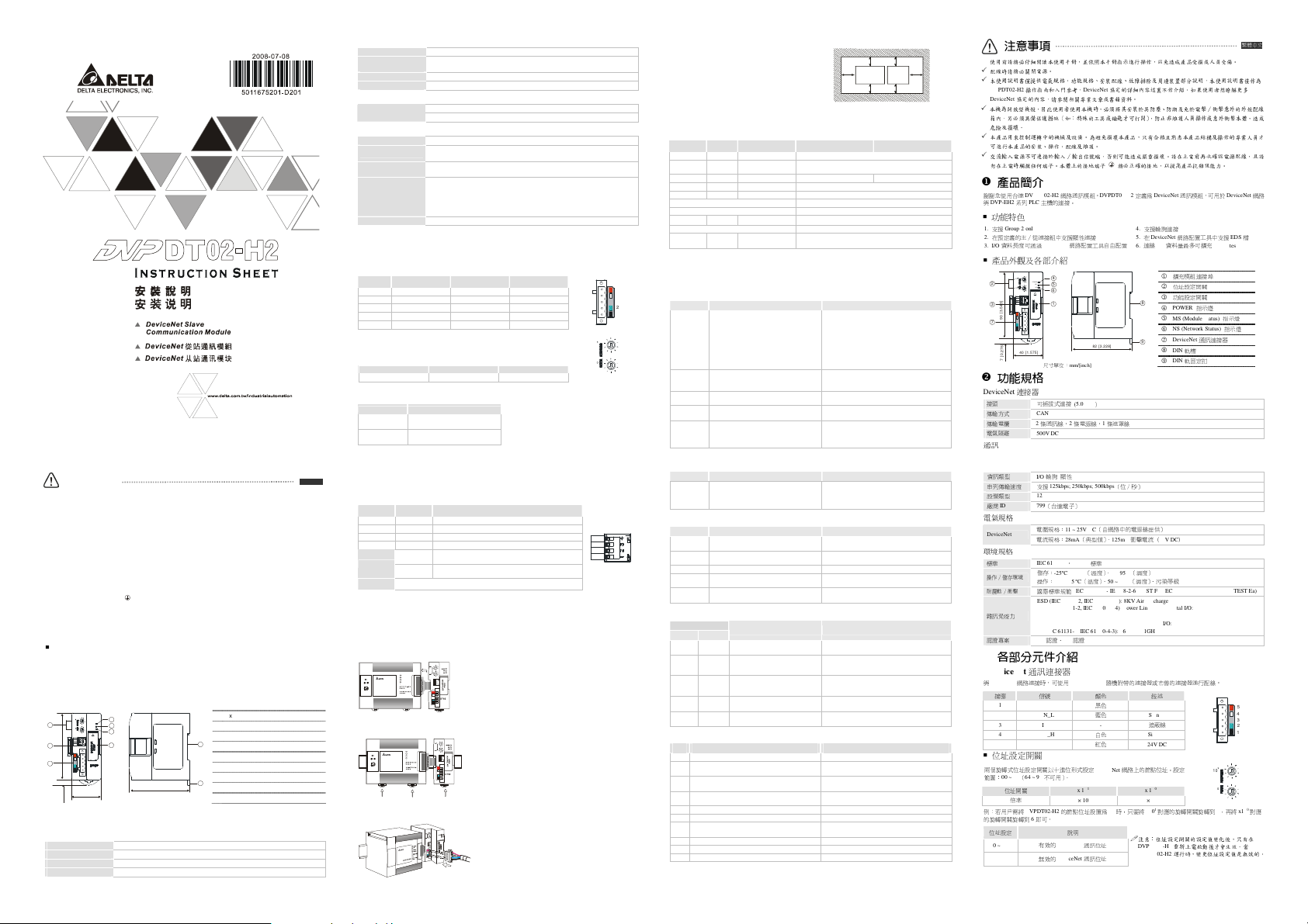
Components
DeviceNet Connector
To connect to DeviceNet network, use the connector enclosed with DVPDT02-H2 or any connectors you can
buy in the store for wiring.
PIN Signal Color Description
1 V- Black 0V DC
2 CAN_L Blue Signal-
3 SHIELD - Shielded cable
4 CAN_H White Signal+
5 V+ Red 24 V DC
Node Address Setup Rotary Switch
The two rotary MAC ID setup switches set up the node addresses on DeviceNet
network in decimal form. Setup range: 00 ~ 63 (64 ~ 99 are forbidden)
Rotary switch x 101 x 100
Multiple × 10 × 1
Example: If you need to set the node address of DVPDT02-H2 as 26, simply switch t he corresponding rotary
switch of x101 to “2” and the corresponding rotary switch of x100 to “6”.
Switch setting Description
0…63 Valid DeviceNet MAC ID
64…99 Invalid DeviceNet MAC ID
Note: The changed values on switches are only valid
when DVPDT02-H2 is re-powered. When
DVPDT02-H2 is operating, changing the set value of
MAC ID will be invalid.
Installation & Wiring
1. Install DVPDT02-H2 in an enclosure with sufficient space
around it to allow heat dissipation (see the figure).
2. DO NOT place the I/O signal wires and power supply wire
in the same wiring circuit.
Control Register
The control registers (CR) are the registers inside DVPDT02-H2. See the table below for the definitions of all
the CRs. DVP-EH2 series PLC MPU can read or write the CR allowed through DFROM/DTO instructions.
CR# Attribute Content High byte Low byte
#0 Read Model name DVPDT02-H2 m odel code = H’0230
#1 Read Firmware version
#2 Read Length of I/O data Length of output I/O data Length of input I/O data
#3 ~ #102 Read/write Input data mapping Area for storing data from DVPDT02-H2 to DeviceNet m aster
#103 ~ #202 Read/write Output data mapping Area for storing data from DeviceNet master to DVPDT02-H2
#203 ~ #215 Set up by the system. DO NOT use it.
#216 ~ #250 Reserved
#251 Read Error
#252 ~ #254 Reserved
#255 Read MPU status
LED Indicators & Trouble-Shooting
5
4
3
2
X
10
X
10
There are 3 LED indicators on DVPDT02-H2. POWER indicator displays the status of working power. NS
indicator and MS indicator display the connection status of the comm unication.
NS LED
LED status Indication How to deal with it?
No power, or DVPDT02-H2 has not completed
Off
the Dup_MAC_ID test yet.
DVPDT02-H2 is on-line and has passed
Green light
Dup_MAC_ID test but has not established
flashes
connections to other nodes.
DVPDT02-H2 is on-line and is normally
Green light on
connected to the master.
Red light
DVPDT02-H2 is on-line, but I/O connections
flashes
are timed-out.
The communication is down; MAC ID is
Red light on
repeated; no network power; bus-off
Displaying the current firmware version in hex, e.g. V1.12 is
indicated as H’0112.
Register for storing errors. See
CR#255 = K0: MPU in STOP status
CR#255 = K1: MPU in RUN status
1. Check the power of DVPDT02-H2 and see if the
connection is normal.
2. Check if the node communication on the network
normal.
3. Make sure at least one or more nodes on the
network are operational at the same time and the
baud rate is the same as that of DVPDT02-H2.
4. Check if the baud rate of DVPDT02-
as that of other nodes.
1. Correctly configure the slave module.
2. Reset the master PLC to be in RUN status.
--
1. Check if the network connection is normal.
2. Check if the master operates normally.
1. Make sure all the MAC IDs on the network are not
repeated.
2. Check if the network installation is normal.
3. Check if the baud rate of DVPDT02-
EH2 PLC
D
D
for error codes.
DT0 2-H 2
指示燈
通訊連接器
200 bytes
指示燈
指示燈
DeviceNet
EDS檔
繁體中文
網路
D
DD
D
D>5 0mm
使用前請務必仔細閱讀本使用手冊,並依照本手冊指示進行操作,以免造成產品受損或人員受傷。
配線時請務必關閉電源。
本使用說明書僅提供電氣規格、功能規格、安裝配線、故障排除及周邊裝置部分說明,本使用說明書僅作為
DVPDT02-H2
DeviceNet
本機為開放型機殼,因此使用者使用本機時,必須將其安裝於具防塵、防潮及免於電擊∕衝擊意外的外殼配線
箱內。另必須具備保護措施(如:特殊的工具或鑰匙才可打開),防止非維護人員操作或意外衝擊本體,造成
危險及損壞。
本產品用來控制運轉中的機械及設備。為避免損壞本產品,只有合格且熟悉本產品結構及操作的專業人員才
可進行本產品的安裝、操作、配線及維護。
交流輸入電源不可連接於輸入∕輸出信號端,否則可能造成嚴重損壞。請在上電前再次確認電源配線,且請
勿在上電時觸摸任何端子。本體上的接地端子
產品簡介
謝謝您使用台達
與
DVP-EH2系列PLC
功能特色
1. 支援Group 2 only servers
2.
在預定義的主∕從連接組中支援顯性連接
3. I/O
資料長度可通過
產品外觀及各部介紹
2
]
3
3
4
5
.
3
[
0
9
7
]
6
7
2
.
0
[
7
功能規格
DeviceNet
接頭
傳輸方式
傳輸電纜
電氣隔離
通訊
操作指南和入門參考,
協定的內容,請參閱相關專業文章或書籍資料。
DeviceNet
協定的詳細內容這裏不作介紹。如果使用者想瞭解更多
務必正確的接地,以提高產品抗雜訊能力。
DVPDT02-H2
網路通訊模組。
主機的連接。
DVPDT02-H2
DeviceNet
網路配置工具自由配置
4
X
10
POWER
MS
5
NS
X
10
6
DR 1
DR 0
IN 1
IN 0
1
40 [1.575]
尺寸單位:
mm/[inch]
連接器
可插拔式連接 (
5.08mm
CAN
2條通訊線、2條電源線、1條遮罩線
500V DC
)
定義為
4.
支援輪詢連接
5. 在DeviceNet
6. 連線I/O
8
DeviceNet
資料量最多可擴充
擴充模組連接埠
1
位址設定開關
2
功能設定開關
3
POWER
4
MS (Module Status)
5
NS (Network Status)
6
DeviceNet
7
DIN軌槽
8
DIN
9
通訊模組,可用於
網路配置工具中支援
軌固定扣
注意事項
Warning
Please read this instruction sheet carefully before use and follow this instruction to operate the device in order to
prevent damages on the device or injuries to staff.
Switch off the power before wiring.
This instruction sheet only provides introductory information on electrical specification, functions, wiring,
trouble-shooting and peripherals for DVPDT02-H2. Details of DeviceNet protocol are not included in this sheet. For
more information on DeviceNet protocol, please refer to relevant reference or literatures.
DVPDT02-H2 is an OPEN-TYPE device and therefore should be installed in an enclosure free of airborne dust,
humidity, electric shock and vibration. The enclosure should prevent non-maintenance staff from operating the device
(e.g. key or specific tools are required to open the enclosure) in case danger and damage on the device may occur.
DVPDT02-H2 is to be used for controlling the operating machine and equipment. In order not to damage it, only
qualified professional staff familiar with the structure and operation of it can install, opera te, wire and maintain it.
DO NOT connect input AC power supply to any of the I/O terminals; otherwise serious damage may occur. Check all
the wiring again before switching on the power, and DO NOT touch any terminal when the power is switched on.
Make sure the ground terminal is correctly grounded in order to prevent electromagnetic interference.
Introduction
Thank you for choosing Delta DVPDT02-H2 DeviceNet communication module. DVPDT02-H2 can be applied
to the connection with DVP-EH2 series PLC MPU in a DeviceNet network.
Features
1. Supports Group 2 only servers.
2. Supports explicit connection in the pre-defined
master/slave connection group.
3. The length of I/O data can be freely configured
through DeviceNet network configuration tool.
Product Profile & Outline
2
]
3
3
4
5
.
3
[
0
9
7
]
6
7
2
.
0
[
7
Specifications
DeviceNet Connector
Type Removable connector (5.08mm)
Transmission method CAN
Transmission cable 2 communication cables, 2 power cables, 1 shielded cable
Electrical isolation 500V DC
X
10
X
10
DR 1
DR 0
IN 1
IN 0
40 [1.575]
POWER
MS
NS
4
5
6
1
Unit: mm/[inch]
4. Supports polling.
5. Supports EDS files in DeviceNet network
configuration tools.
6. I/O data is extendable to 200 bytes.
1
2
3
8
4
5
6
7
9
8
9
ENGLISH
Extension port
Node address setup rotary switch
Function setup DIP switch
POWER indicator
MS (Module Status) indicator
NS (Network Status) indicator
DeviceNet connector
DIN rail
DIN rail clip
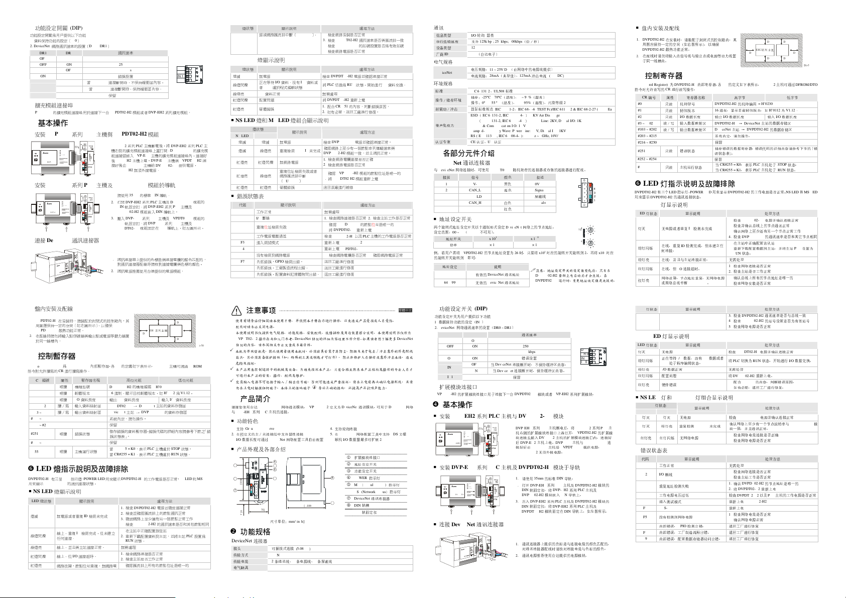
Function Setup DIP Switch
The function setup switches are for:
1. Setting up I/O data holding function (IN0)
2. Setting up the baud rates of DeviceNet network (DR0 ~ DR1)
DR1 DR0 Baud rate
OFF OFF 125kbps
OFF ON 250kbps
ON OFF 500kbps
ON ON Incorrect setting
IN0
IN1 Reserved
Extension Port
The extension port on DVPDT02-H2 is used for the connection to the next DVPDT02-H2 or extension modules
of DVP-EH2 series PLC MPU.
When the DeviceNet connection is interrupted, the content in
OFF
the buffer area will not be held.
When the DeviceNet connection is interrupted, the content in
ON
the buffer area will be held.
DR 1
DR 0
IN 1
IN 0
Basic Operation
Connecting DVPDT02-H2 to DVP-EH2 Series PLC MPU
POWER
RUN
RUN
STOP
ERROR
BAT.LOW
0 1
IN
OUT
DVP -20 E H
Install DVP-EH2 and DVPDT02-H2 on DIN Rail
POWER
RUN
STOP RUN
ERROR
BAT.LOW
0 1
IN
OUT
DVP- 20E H
Connecting to DeviceNet Connector
Switch off DVP-EH2. Open the connection port on the
right hand side of DVP-EH2 and connect DVPDT02-H2 to
DVP-EH2. Switch on DVP-EH2, and DVP-EH2 will supply
power to DVPDT02-H2. There is no need to connect
DVPDT02-H2 to an external power supply.
1. Use 35mm DIN rail.
2. Open the DIN rail clips on DVP-E H2 and
DVPDT02-H2. Insert DVP-EH2 and DVPDT02-H2
onto the DIN rail.
3. Clip up the DIN rail clips on DVP-EH2 and
DVPDT02-H2 to fix DVP-EH2 and DVPDT02-H2 on
the DIN rail.
As shown in the figure.
1. T he colors of the PINs on the DeviceNet connector
match the c olors of the connection cables. Make sure
you connect the cable to the right PIN.
2. We recommend you also apply Delta’s power module
in the connection.
As shown in the figure.
LED status Indication How to deal with it?
MS LED
LED status Indication How to deal with it?
Off No power
Green light
Waiting for I/O data; no I/O data; the program
flashes
of DVPDT02-H2 is being edited.
Green light on I/O data are normal --
Red light
Recoverable fault Re-power DVPDT02-H2
flashes
Red light on Hardware error
NS LED + MS LED
LED status
NS LED MS LED
Off Off No power
Green light
Off
on
Red light
Red light
on
flashes
Red light
Green light
on
on
Red light
Red light on Hardware error Send yo ur DVPDT02-H2 back to the factory for repair.
on
Error Codes
Code
00 DVPDT02-H2 operates normally. --
E2 I/O off-line
F0 Dup_MAC_ID test has failed.
F2 Working power in low voltage
F3 Entering test mode Re-power DVPDT02-H2
F4 BUS-OFF Re-power DVPDT02-H2
F5 No network power detected
F7 Internal error. GPIO detection error. Send your DVPDT02-H2 back to the factory for repair.
F8 Internal error. Manufacturing error. Send your DVPDT02-H2 back to the factory for repair.
F9 Internal error. Configured memory polling error. S end your DVPDT02-H2 back to the factory for repair.
Indication How to deal with it?
DVPDT02-H2 has not completed the
Dup_MAC_ID test yet.
No network power
Dup_MAC_ID test has failed; bus-off
Description How to deal with it?
with that of the network.
4. Check if the node address of DVPDT02-H2 is a
valid one.
5. Check if the network power is normal.
Check the power of DVPDT02-H2 and see if the
connection is normal.
Switch DVPDT02-H2 to RUN status to start I/O data
exchange.
1. Find out the cause of error in CR#251.
2. Send back to t he factory for repair if necessary.
Check the power of DVPDT02-H2 and see if the
connection is normal.
Make sure at least one or more node
operational at the same time and baud rate as the
DVPDT02-H2 module.
DVPDT02-H2.
2. Check if the network power works normally.
1. Make sure DVPDT02-H2 has a unique address.
2. Re-power DVPDT02-H2.
1. Check if the network connection is normal.
2. Check if the master operates normally.
1. Make sure DVPDT02-H2 has a unique address.
2. Re-power DVPDT02-H2.
Check if the power of DVPDT02-H2 and MPU is
normal.
1. Check if the network cable works normally.
2. Check if the network power works normally.
資訊類型
I/O輪詢 顯性
串列傳輸速度 支援
設備類型
廠商
ID 799
電氣規格
DeviceNet
環境規格
標準
IEC 61131-2、UL508標準
操作∕儲存環境
耐震動∕衝擊
雜訊免疫力
認證專案
各部分元件介紹
DeviceNet
與
DeviceNet
接腳
1 V-
2 CAN_L
3 SHIELD -
4 CAN_H
5 V+
位址設定開關
兩個旋轉式位址設定開關以十進位形式設定
範圍:
00 ~ 63(64 ~ 99
例:若用戶需將
的旋轉開關旋轉到6即可。
位址設定
0 ~ 63
64 ~ 99
125kbps; 250kbps; 500kbps
12
(台達電子)
電壓規格:
11 ~ 25V DC
電流規格:
CE
網路連接時,可使用
28mA
儲存:
-25ºC ~ 70ºC
操作:
0ºC ~ 55 ºC
國際標準規範
IEC 61131-2、IEC 68-2-6 (TEST Fc)/IEC 61131-2 & IEC 68-2-27 (TEST Ea)
ESD (IEC 61131-2, IEC 61000-4-2): 8KV Air Discharge
EFT (IEC 61131-2, IEC 61000-4-4): Power Line: 2KV, Digital I/O: 1KV
Analog & Communication I/O: 1KV
Damped-Oscillatory Wave: Power Line: 1KV, Digital I/O: 1KV
RS (IEC 61131-2, IEC 61000-4-3): 26MHz ~ 1GHz, 10V/m
認證、UL認證
通訊連接器
DVPDT02-H2
信號
不可用)。
DVPDT02-H2
的節點位址設置為26時,只要將
有效的
DeviceNet
無效的
DeviceNet
說明
位址開關
倍率
(位∕秒)
(由網路中的電源線提供)
(典型值)、
125mA
衝擊電流
(
(溫度)、
5 ~ 95%
(濕度)
50 ~ 95%
(濕度)、污染等級
(溫度)、
隨機附帶的連接器或市售的連接器進行配線。
顏色
黑色
藍色
白色
紅色
DeviceNet
x 101 x 100
× 10 × 1
通訊位址
通訊位址
敍述
0V DC
Signal-
遮蔽線
Signal+
24V DC
網路上的節點位址。設定
1
x10
注意:位址設定開關的設定值變化後,只有在
DVPDT02-H2
DVPDT02-H2
24V DC
)
2
X
10
X
10
對應的旋轉開關旋轉到2,再將
重新上電啟動後才會生效。當
運行時,變更位址設定值是無效的。
0
x10
對應
Page 2
9
82 [3.228]
1
2
4
10
功能設定開關
功能設定開關為用戶提供以下功能
1.
資料保持功能的設定(
2. DeviceNet
擴充模組連接埠
DVPDT02-H2
安裝DVP-EH2系列PLC
RUN
STOP
0 1
(DIP)
IN0
)
網路通訊速率的設置(
DR1 DR0
OFF OFF 125kbps
OFF ON 250kbps
ON OFF 500kbps
ON ON
IN0
IN1
的擴充模組連接埠用於連接下一台
基本操作
DR0 ~ DR1
當
DeviceNet
OFF
當
DeviceNet
ON
主機與
POW E R
RU N
ERR O R
BAT.L O W
IN
OUT
DVP-20 EH
安裝DVP-EH2系列PLC
POWER
RUN
RUN
STOP
ERROR
BAT.LOW
0 1
IN
OUT
DVP -2 0E H
連接DeviceNet
盤內安裝及配線
1. DVPDT02-H2
在安裝時,請裝配於封閉式的控制箱內,其
周圍應保持一定的空間(如右圖所示),以確保
DVPDT02-H2
散熱功能正常。
2.
在配線時請勿將輸入點信號線與輸出點或電源等動力線置
於同一線槽內。
控制暫存器
CR (Control Register) 爲DVPDT02-H2
指令對允許讀寫的CR進行讀寫操作。
CR
編
號 屬
性 暫存器
唯讀 機種型號
#0
唯讀 韌體版本
#1
唯讀
#2
讀∕寫 輸入資料映射區
#3 ~ #102
讀∕寫 輸出資料映射區
#103 ~ #202
#203 ~ #215
#216 ~ #250
唯讀 錯誤
#251
#252 ~ #254
唯讀 主機運行
#255
LED
燈指示說明及故障排除
DVPDT02-H2
有三個
用來顯示
NS LED
LED
燈
綠燈閃爍
綠燈亮 線上,並且與主站連接正常。
紅燈
紅燈
LED
DVPDT02-H2
燈顯示說明
燈
狀態
滅 無電源或者
線上,
任何
連接。
閃爍 線上,
亮
網路故障,節點位址重複、無網路電
主機及
通訊連接器
內部暫存器,各CR的定義如下表所示,
名稱
DVPDT02 -H2
1 6
I/O
資料長度 輸出
DVPDT02-H2 → DeviceNet
DeviceNet
狀態
狀態
指示燈,
POWER LED
的通訊連接狀態。
顯示說明
重複ID檢測未完成
重複ID檢測完成,但未建立
但
I/O
連接超時。
)
通訊速率
DR 1
DR 0
DVP-EH2
IN 1
IN 0
系列擴充模組。
錯誤設置
連接斷開時,不保持緩衝區內容。
連接斷開時,保持緩衝區內容。
保留
DVPDT02-H2
模組或者
DVPDT02-H2模組
DVP-EH2系列PLC
機右側的擴充模組連接埠上蓋打開,
組連接頭插入
後
接好後由
DVPDT02-H2
1.
2. 打開DVP-EH2系列PLC
3. 壓入DVP-EH2系列PLC
1.
2.
系統內定,請勿操作。
保留
儲存錯誤的資料暫存器,錯誤代碼的詳細內容請參考下節之「錯
誤狀態表」。
保留
當
當
主機斷電後,將
DVP-EH2系列PLC
DVP-EH2
DVP-EH2
主機上電。
DVP-EH2
無須外接電源。
DVPDT02-H2
請使用
35mm
的標準
DIN
軌固定扣,將
DVPDT02-H2
DIN
軌固定扣,將
DVPDT02-H2
通訊連接器上提供的色標是與連接電纜的顏色匹配的,
對通訊連接器配線時請核對連接電纜與色標的顏色。
通訊電源推薦使用台達提供的電源模組。
高位元
組
的機
進制,顯示
目前韌體版本
I/O
資料長度
主
站 →
DVPDT02-H2
CR#255 = K0
,表示
CR#255 = K1
,表示
DVPDT02-H2
主機的擴充模組連接埠內,連接好
DVP-EH2
主機與
主機給
DVPDT02-H2
模組於導軌
DIN
導軌。
主機及
DVPDT02-H2
DVP-EH2系列PLC
模組嵌入
DIN
導軌上。
主機及
DVPDT02-H2
DVP-EH2系列PLC
模組固定在
DIN
導軌上,如左圖所示。
D
EH2
系列主機
DT02 -H2
D
DVP-EH2
主機可通過
種編碼
= H’0230
,如
H’0112為V1.12。
輸入
I/O
資料長度
主站的資料存儲區
的資料存儲區
PLC
主機處於
STOP
PLC
主機處於
RUN
DVPDT02-H2
提供電源,
主機及
主機及
D
DD
D
DFROM/DTO
低位元
狀態
。
狀態
。
組
的擴充模
模組的
模組的
用來顯示
DVPDT02-H2
1. 檢查DVPDT02-H2
2.
檢查並確認匯流排
3.
確認網路上
4. 檢查DVPDT02-H2
1.
在主站中正確配置該從
2.
重新下載
配置資料到主站,並將主
RUN
狀態
。
無需
處理
1.
檢查
網路連接是否正常
2.
檢查主站是否
1.
確認匯流排上所有的節點位址是唯一的
的工作電源是否正常,
至少還有另
工作正常
NS LED和MS LED
處理方法
電源並確認連接正常
上的節點通訊正常
的通訊速率是否和其他節點相同
一個節點正常工作
站
站
PLC
設置為
D>50 mm
主
連
LED
燈
狀態
顯示說明
源或網路匯流排中斷(
MS LED
燈顯示說明
LED
燈
狀態
燈
滅 無電源
正在等
綠燈閃爍
者
PLC
綠燈亮
I/O
閃爍 配置
亮 硬體
資料正常
紅燈
紅燈
NS LED燈和MS LED
LED
燈
狀態
NS LED MS LED
燈
滅 燈
滅 無電源
燈
滅 綠燈亮 重複檢測
紅燈
亮 紅燈
閃爍 無網路電源
紅燈
亮 綠燈亮
紅燈
亮 紅燈
錯誤狀態表
代碼
工作正常
00
I/O斷線 1.
E2
重複位址檢測失敗
F0
工作電源電壓過
F2
進入測試模式
F3
F4 BUS-OFF
沒有檢測
F5
內部錯誤,
F7
內部錯誤,工廠製造流程出錯。 退回
F8
內部錯誤,配置資料
F9
注意事項
使用前请务必仔细阅读本使用手册,并依照本手册指示进行操作,以免造成产品受损或人员受伤
配线时请务必关闭电源
本使用说明书仅提供电气规格、功能规格、安装配线、故障排除及周边装置部分说明,本使用说明书仅作为
DVPDT02-H2
操作指南和入门参考
协议的内容,请参阅相关专业文章或书籍资料
本机为开放型机壳,因此使用者使用本机时,必须将其安装于具防尘、防潮及免于电击∕冲击意外的外壳配线
箱内。另必须具备保护措施
危险及损坏
。
本产品用来控制运转中的机械及设备。为避免损坏本产品,只有合格且熟悉本产品结构及操作的专业人员才
可进行本产品的安装、操作、配线及维护
交流输入电源不可连接于输入∕输出信号端,否则可能造成严重损坏。请在上电前再次确认电源配线,且请
勿在上电时触摸任何端子。本体上的接地端子
產品簡介
谢谢您使用台达
DVPDT02-H2
与
DVP-EH2系列PLC
功能特色
1. 支持 Group 2 only servers
2.
在预定义的主∕从连接组中支持显性连接
3. I/O
数据长度可通过
产品外观及各部介绍
X
10
POWER
2
MS
NS
X
10
DR 1
DR 0
IN 1
]
IN 0
3
3
4
5
.
3
[
0
9
7
]
6
7
2
.
40 [1.575]
0
[
7
功能規格
DeviceNet
连接器
接头 可插拔式连接
传输方式
传输电缆
电气隔离
BUS-OFF)。 2.
顯示說明
待
I/O
資料、沒有
I/O
處於程式編輯狀態
問題
錯誤
資料或
燈組合顯示說明
顯示說明
MAC ID
未完成
重複位址檢測失敗
亮 硬體
到網路電源
GPIO
。
主机的连接。
DeviceNet
或者
網路匯流排中斷
(
BUS-OFF)
錯誤
顯示說明
低
1.
檢測
出錯。 退回
記憶體詢問
出錯。 退回
,
DeviceNet
(
如:特殊的工具或钥匙才可打开) ,
。
网络通讯模块。
DVPDT02-H2
网络配置工具自由配置
4
5
6
1
尺寸单位:
mm/[inch]
(
5.08mm
CAN
2
条通讯线、2条电源线、1条屏蔽线
500V DC
)
檢查
3. 檢查DVPDT02-H2
4. 檢查DVPDT02-H2
5.
檢查
檢查
將
PLC
無需
將
DVPDT02-H2
1.
配
2.
如有必要,退回工廠進行修復。
檢查
確認網路上至少有一個節點串列傳輸速率與
DVPDT02-H2
1.
檢查
2.
檢查
1. 確認DVPDT02-H2
2. 將DVPDT02-H2
送回原
無需
檢查
1. 確認DVPDT02-H2
2. 將DVPDT02-H2
檢查
重新
重新
檢查
协议的详细内容这里不作介绍。如果读者想了解更多
。
务必正确的接地,以提高产品抗噪声能力
處理方法
網路安裝是否正常
網路電源是否正常
DVPDT02-H2
切換
為
處理
合
CR#251
DVPDT02-H2
網路電纜連接是否正確
網路電源是否正常
廠進行
處理
網路連接是否正常
DVPDT02-H2以及PLC
上電
DVPDT02-H2
上電
DVPDT02-H2
網路電纜是否正常
工廠進行
工廠進行
工廠進行
通訊速率是否與匯流排一
的站號設置是否為有效站號
處理方法
電源並確認連接正常
RUN
狀態,開始
進行IO資料交換。
重新
上電
的內容,判斷錯誤原因。
處理方法
電源並確認連接正常。
模組一致,並且通訊正常。
模組的節點位址是唯一的
模組重新上電
處理方法
2.
檢查主站
的節點位址是唯一的
重新
上電
主機的工作電源是否正常
2.
確認網路電源正常
維修
修復
修復
修復
防止非维护人员操作或意外冲击本体,造成
定义为
DeviceNet
通讯模块,可用于
4.
支持轮询连接
5. 在DeviceNet
网络配置工具中支持
6. 联机I/O
8
数据量最多可扩展
1
2
3
4
5
6
7
8
9
扩展模块连接口
地址设定开关
功能设定开关
POWER
指示灯
MS (Module Status
NS (Network Status
DeviceNet
DIN
轨槽
DIN
轨固定扣
200 bytes
通讯连接器
工作是否正常
。
。
DeviceNet
EDS文檔
) 指示灯
) 指示灯
簡體中文
DeviceNet
通讯
信息类型
致
网络
I/O轮询 显性
串行传输速度 支持
设备类型
厂商
ID 799
电气规格
DeviceNet
环境规格
标准
操作∕储存环境
耐震动∕冲击 国际标准规范
噪声免疫力
认证专案
各部分元件介紹
DeviceNet
与
DeviceNet
接脚
1 V-
2 CAN_L
3 SHIELD -
4 CAN_H
5 V+
地址设定开关
两个旋转式地址设定开关以十进制形式设定
设定范围:
地址开关
例:若用户需将
的旋转开关旋转到6即可。
地址设定 说明
0 ~ 63
64 ~ 99
功能设定开关
功能设定开关为用户提供以下功能
1.
数据保持功能的设定(
2. DeviceNet
DR1 DR0
OFF OFF 125kbps
OFF ON 2 50kbps
ON OFF 500kbps
ON ON
IN0
IN1
扩展模块连接口
DVPDT02-H2
基本操作
125k bps; 250kbps; 500kbps
12
(台达电子)
电压规格:
11 ~ 25V DC
电流规格:
28mA
(典型值)、
IEC 61131-2、UL508标准
-25ºC ~ 70ºC
储存:
操作:
0ºC ~ 55 ºC
(温度)、
IEC 61131-2、IEC 68-2-6 (TEST Fc)/IEC 61131-2 & IEC 68-2-27 (TEST Ea)
ESD(IEC 61131-2, IEC 61000-4-2): 8KV Air Discharge
EFT(IEC 61131-2, IEC 61000-4-4): Power Line: 2KV, Digital I/O: 1KV
Analog & Communication I/O: 1KV
Damped-Oscillatory Wave: Power Line: 1KV, Digital I/O: 1KV
RS (IEC 61131-2, IEC 61000-4-3): 26MHz ~ 1GHz, 10V/m
CE
认证、UL认证
通讯连接器
信号
不可用)。
DVPDT02-H2
的节点地址设置为26时,只要将
有效的
(DIP)
IN0
)
OFF
ON 当DeviceNet
DVPDT02-H2
x 101 x 100
DeviceNet
DeviceNet
DR0 ~ DR1
当
DeviceNet
网络连接时,可使用
00 ~ 63(64 ~ 99
倍率
× 10 × 1
无效的
网络通讯速率的设置(
的扩展模块连接口用于连接下一台
安装DVP-EH2系列PLC
POW E R
RUN
RUN
STOP
ERR O R
BAT.L O W
0 1
IN
OUT
DVP-20 EH
安装DVP-EH2系列PLC
POWER
RUN
STOP RUN
ERROR
BAT.LOW
0 1
IN
OUT
DVP -2 0E H
连接DeviceNet
通讯连接器
(位∕秒)
(由网络中的电源线提供)
125mA
冲击电流 (
24V DC
(温度)、
5 ~ 95%
(湿度)
50 ~ 95%
(湿度)、污染等级
随机附带的连接器或市售的连接器进行配线。
颜色
叙述
黑色
0V DC
蓝色
Signal-
白色
Signal+
红色
DeviceNet
通讯地址
通讯地址
)
连接断开时,不保持缓冲区内容。
保留
主机与
主机及
屏蔽线
24V DC
网络上的节点地址。
1
x10
对应的旋转开关旋转到2,再将
注意:地址设定开关的设定值变化后,只有在
DVPDT02-H2
重新上电启动后才会生效。当
DVPDT02-H2
运行时,变更地址设定值是无效的
通讯速率
错误设置
连接断开时,保持缓冲区内容。
DVPDT02-H2
模块或者
DVP-EH2
DVPDT02-H2模块
DVP-EH2系列PLC
机右侧的扩展模块连接口上盖打开,
块连接头插入
后
接好后由
DVPDT02-H2
DVPDT02-H2
1.
2. 打开DVP-EH2系列PLC
3. 压入DVP-EH2系列PLC
DVP-EH2
DVP-EH2
请使用
DIN
轨固定扣,将
DVPDT02-H2
DIN
轨固定扣,将
DVPDT02-H2
主机断电后,将
DVP-EH2
主机的扩展模块连接口内,连接好
主机上电。
DVP-EH2
主机给
无须外接电源。
模块于导轨
35mm
的标准
DIN
DVP-EH2系列PLC
模块嵌入
DVP-EH2系列PLC
模块固定在
DVPDT02-H2
DIN
1.
通讯连接器上提供的色标是与连接电缆的颜色匹配的,
对通讯连接器配线时请核对连接电缆与色标的颜色。
2.
通讯电源推荐使用台达提供的电源模块。
)
2
X
X
10
DR 1
DR 0
IN 1
IN 0
系列扩展模块。
DVP-EH2系列PLC
DVPDT02-H2
主机与
提供电源,
导轨。
主机及
DVPDT02-H2
导轨上。
主机及
DVPDT02-H2
DIN
导轨上,如左图所示。
5
3
的扩展模
DVPDT02-H2
主机及
主机及
x10
模块的
模块的
0
对应
。
主
连
盘内安装及配线
1. DVPDT02-H2
周围应保持一定的空间(如右图所示),以确保
DVPDT02-H2
2.
在配线时请勿将输入点信号线与输出点或电源等动力线置
于同一线槽内。
控制寄存器
CR (Control Register) 为DVPDT02-H2
指令对
允许读写
CR
编
#0
#1
#2
#3 ~ #102
#103 ~ #202
#203 ~ #215
#216 ~ #250
#251
#252 ~ #254
#255
LED
DVPDT02-H2
用来显示
NS LED
LED
灯
灯
灭 无电源或者
绿灯闪烁
在安装时,请装配于封闭式的控制箱内,其
散热功能正常。
的CR进行读写操作。
号 属
只
只
只
读∕写 输入数据映射区
读∕写 输出数据映射区
只
只
燈指示說明及故障排除
有三个
DVPDT02-H2
灯显示说明
状态
在线,
何
连接。
内部寄存器,
性 寄存器名称
读 机种型号
读 韧体版本
读
I/O
读 错误
读 主机运行
LED
的通讯连接状态。
数据长度 输
状态
指示灯,
POWER LED
DVPDT02-H2
状态
显示说明
重复ID检测未完成
重复ID检测完成,但未建立任
各CR的定义如下表所示,
16
进制,显示
出
DVPDT02-H2 → DeviceNet
DeviceNet
系统内定,请勿操作。
保留
储存错误的数据寄存器,错误代码的详细内容请参考下节的「错
误
状态表」
保留
当
CR#255 = K0
当
CR#255 = K1
用来显示
绿灯亮 在线,并且与主站连接正常。 无需
红灯
闪烁 在线,
但
I/O
连接超时。
待
I/O
到网络电源
GPIO
(BUS-OFF)。
显示说明
显示说明
数据、没有
。
灯组合显示说明
显示说明
MAC ID
显示说明
低
检测出
错。
I/O
访问出
数据或者
未完成
错。 退回
网络故障,节点地址重复、无网络电源
红灯
亮
或网络总线中断
LED
灯
状态
MS LED
灯显示说明
LED
灯
状态
灯
灭 无电源
正在等
绿灯闪烁
PLC
绿灯亮
红灯
红灯
NS LED灯和MS LED
处于程序编辑状态
I/O
数据正常
闪烁 配置
问题
亮 硬件
错误
LED
灯
状态
NS LED MS LED
灯
灭 灯
灭 无电源
灯
灭 绿灯亮 重复检测
红灯
亮 红灯
闪烁 无网络电源
错误状态表
代码
00
工作正常
E2
I/O断线
F0
重复地址检测失败
F2
工作电源电压过
F3
进入测试模式
F4 BUS-OFF
F5
没有检测
F7
内部错误,
F8
内部错误,工厂制造流程出错。 退回
F9
内部错误,配置数据存储器
EH2
系列主机
DVP-EH2
高字
节
的机
种编码
= H’0230
目前韧体版本
I/O
数据长度
DVPDT02-H2
1. 检查DVPDT02-H2
2.
3.
4. 检查DVPDT02-H2
1.
2.
1.
2.
1.
2.
3. 检查DVPDT02-H2
4. 检查DVPDT02-H2
5.
检查
将
无需
将
1.
2.
,如
主站的数据存储区
主
站 →
DVPDT02-H2
。
,表示
PLC
主机处于
,表示
PLC
主机处于
的工作电源是否正常
处理方法
线上的节点通讯正常
至少还有另
配置数据到主站,并将主
状态
。
处理
网络连接是否正常
工作正常
网络安装是否正常
网络电源是否正常
DVPDT02-H2
切换
为
RUN
处理
重新
合
CR#251
的内容,判断错误原因。
电源并确认连接正常
的通讯速率是否和其它节点
处理方法
通讯速率是否与总线一
的站号设置是否为有效站号
处理方法
电源并确认连接正常
状态,开始
上电。
检查并确认总
确认网络上
在主站中正确配置该从
重新下载
RUN
检查
检查主站是否
确认总线上所有的节点地址是唯一的
检查
检查
PLC
DVPDT02-H2
配
如有必要,退回工厂进行修复。
DVPDT02-H2
电源并确认连接正常
网络电缆连接是否正确
网络电源是否正常
处理
网络连接是否正常
工作是否正常
重新
DVPDT02-H2以及PLC
上电
DVPDT02-H2
上电
DVPDT02-H2
网络电缆是否正常
工厂进行
修复
工厂进行
修复
工厂进行
修复
处理方法
处理方法
的节点地址是唯一的
检查
确认网络上至少有一个节点波特率与
块一致,并且通讯正常。
1.
检查
2.
检查
无需
1.
检查
2.
检查主站
1. 确认DVPDT02-H2
2. 将DVPDT02-H2
检查
重新
重新
1.
检查
2.
确认网络电源正常
退回
D
D
DT02 -H 2
D
D
主机可通过
低字
H’0112为V1.12。
输入
I/O
数据长度
的数据存储区
STOP
状态
RUN
状态
;
NS LED和MS LED
一个节点正常工作
站
站
进行
I/O
DVPDT02-H2
上电
主机的工作电源是否正常
DD
D>5 0m m
DFROM/DTO
节
。
。
PLC
设置为
致
数据交换。
相同
模
 Loading...