

Page 1
DTC124TH / DTC124TE / DTC124TUA /
Transistors
DTC124TKA / DTC124TSA
Digital transistors (built-in resistor)
DTC124TH / DTC124TE / DTC124TUA /
DTC124TKA / DTC124TSA
Features
!!!!
1) Built-in bias resistors enable the configuration of an
inverter circuit without connecting external input
resistors (see equivalent circuit).
2) The bias resistors consist of thinfilm resistors with
complete of the input. They also have the advantage
of almost completely eliminating parasitic effects.
3) Only the on/off conditions need to be set for operation,
making device design easy.
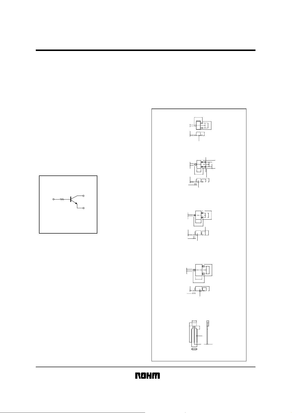
Equivalent circuit
!!!!
B
B : Base
C : Collector
E : Emitter
R1
C
E
External dimensions
!!!!
DTC124TH
ROHM : EMT3 Flat lead
EIAJ : SC-89
DTC124TE
ROHM : EMT3
EIAJ : SC-75A
DTC124TUA
ROHM : UMT3
EIAJ : SC-70
(Units : mm)
1.6
0.85
(1)
(2)
0.27
(3)
0.12
Abbreviated symbol : 05
(3)
0.3
0.15
0.1Min.
Abbreviated symbol : 05
)
(
0.3
0.15
0.1~0.4
Abbreviated symbol : 05
1.0
0.5 0.5
0.7
0to0.1
0.2
(1)
(2)
0.50.5
0.8
0.2
1.6
1.6
0.7
0.55
0~0.1
)
1
(
0.65
)
2
1.3
(
3
0.65
1.25
2.1
0.2
0.9
0.7
0~0.1
1.6
(1) Emitter
(2) Base
(3) Collector
1.0
(1)Emitter
(2)Base
(3)Collector
2.0
Each lead has same dimensions
(1)Emitter
(2)Base
(3)Collector
DTC124TKA
ROHM : SMT3
EIAJ : SC-59
DTC124TSA
ROHM : SPT
EIAJ : SC-72
)
1
(
)
2
)
(
3
0.95 0.95
(
0.4
1.6
2.8
0.3~0.6
0.15
0.8
0.1
~
0
Abbreviated symbol : 05
42
3
3Min.
)
0.45
15Min.
(
0.45
2.5
0.5
5
(1)(2)(3)
1.9
2.9
Each lead has same dimensions
1.1
(1)Emitter
(2)Base
(3)Collector
Taping specifications
(1)
Emitter
(2)
Collector
(3)
Base
Page 2
DTC124TH / DTC124TE / DTC124TUA /
Transistors
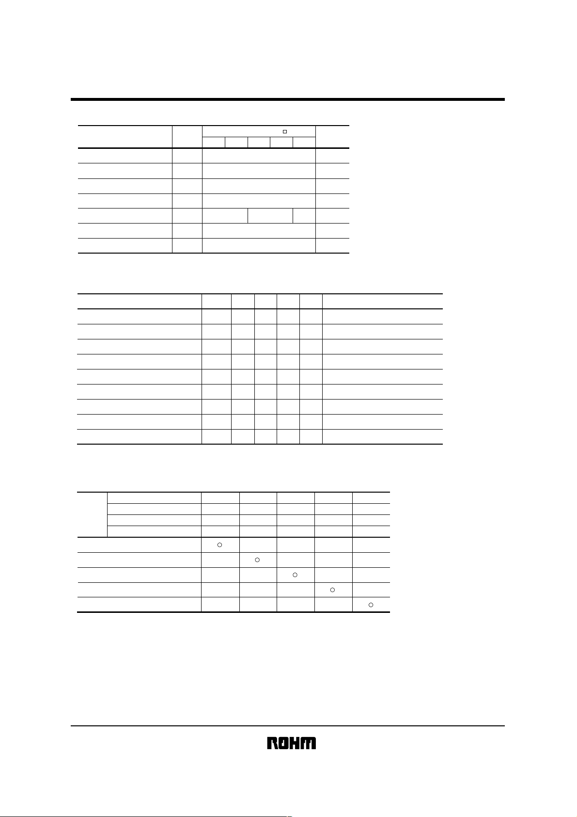
Absolute maximum ratings
!!!!
Parameter Symbol
Collector-base voltage
Collector-emitter voltage
Emitter-base voltage
Collector current
Collector power dissipation
Junction temperature
Storage temperature
Electrical characteristics
!
Parameter Symbol
Collector-base breakdown voltage
Collector-emitter breakdown voltage
Emitter-base breakdown voltage
Collector cutoff current
Emitter cutoff current
Collector-emitter saturation voltage
DC current transfer ratio
Input resistance
Transition frequency
∗Transition frequency of the device
(Ta = 25°C)
V
CBO
CEO
V
V
EBO
I
C
Pc
Tj
Tstg
(Ta = 25°C)
BV
BV
BV
I
I
V
CE(sat)
Limits(DTC124T )
H
EUAKASA
50
50
5
100
150
200
300
150
−55 ~ +150
Min. Typ. Max. Conditions
−−
50
−
50
−
5
−
−
−
−
−
−
100
250
15.4
22
−−
250
CBO
EBO
h
R
f
CBO
CEO
EBO
FE
1
T
−
−
0.5
0.5
0.3
600
28.6
Unit
µA
µA
kΩ
MH
V
V
V
V
−
Z
DTC124TKA / DTC124TSA
Unit
V
V
V
mA
mW
°C
°C
IC=50µA
I
C
=1mA
I
E
=50µA
CB
=50V
V
VEB=4V
C/IB
=5mA/0.5mA
I
CE
=5V,IC=1mA
V
−
V
CE
=10V,IE=−5mA,f=100MH
∗
Z
Packaging specifications
!
Package
Packaging type
Code
Part No.
Basic ordering unit (pieces)
DTC124TH
DTC124TE
DTC124TUA
DTC124TKA
DTC124TSA
EMT3H
EMT3
UMT3
SMT3 SST3
Taping Taping Taping Taping Taping
8000
TLT2L
3000
T106
3000
T146
3000
TP
5000
−−−−
−
−
−
−
−
−
−
−
−
−
−
−
−
−
−
−
Page 3

DTC124TH / DTC124TE / DTC124TUA /
Transistors
Electrical characteristic curves
!!!!
1k
500
FE
200
100
50
20
10
5
DC CURRENT GAIN : h
2
1
100µ 200µ 500µ 1m 2m 5m 10m 20m 50m 100m
Ta=100˚C
25˚C
-40˚C
COLLECTOR CURRENT : I
VCE=5V
C
(A)
Fig.1 DC current gain vs. collector
current
1
(V)
lC/lB=10
500m
CE(sat)
200m
100m
50m
20m
10m
COLLECTOR SATURATION VOLTAGE : V
Ta=100˚C
25˚C
-40˚C
5m
2m
1m
100µ 200µ 500µ 1m 2m 5m 10m 20m 50m 100m
COLLECTOR CURRENT : IC(A)
Fig.2 Collector-emitter saturation
voltage vs. collector current
DTC124TKA / DTC124TSA
 Loading...