

Page 1
Elektronische Bauelemente
A suffix of “-C” specifies halogen & lead-free
FEATURES
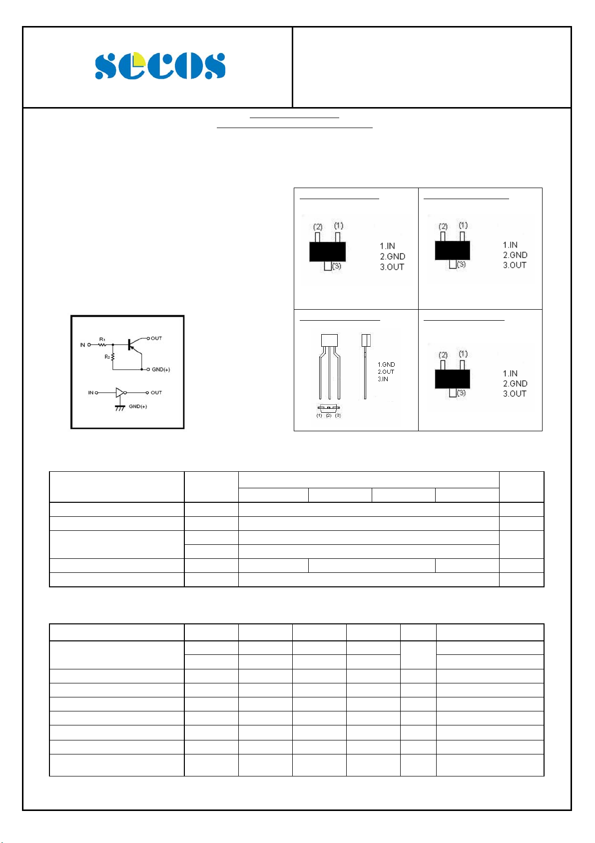
Built-in bias resistors enable the configuration of
an inverter circuit without connecting external
input resistors (see equivalent circuit).
The bias resistors consist of thin-film resistors
with complete isolation to allow positive biasing
of the input. They also have the advantage of
almost completely eliminating parasitic effects.
Only the on/off conditions need to be set for
operation, making device design easy.
EQUIVALENT CIRCUIT
RoHS Compliant Product
DTA124EE / DTA124EUA / DTA124ECA /
DTA124ESA
PNP Digital Transistors (Built-in Resistors)
DTA124EE (SOT-523)
Addreviated symbol:15
DTA124ESA (TO-92S)
DTA124EUA (SOT-323)
Addreviated symbol:15
DTA124ECA (SOT-23)
Addreviated symbol:15
ABSOLUTE MAXIMUM RATINGS at (TA = 25°C unless otherwise noted)
Parameter Symbol
E UA CA SA
Supply Voltage VCC -50 V
Input Voltage VIN -40 ~ 10 V
I
-30
Output Current
Power dissipation PD 150 200 300 mW
Junction & Storage temperature TJ, T
O
I
-100
C(MAX)
150, -55~150 ℃
STG
Limits (DTA124E□)
Unit
mA
ELECTRICAL CHARACTERISTICS at (TA = 25°C unless otherwise noted)
Parameter Symbol
Input Voltage
Output Voltage V
Input Current I
Output Current I
DC Current Gain G
Input Resistance R
Resistance ratio R
Transition frequency f
V
V
2
- - -0.5 V VCC= -5V, IO= -100A
I(off)
-3 - - VO= -0.2V, IO= -5mA
I(on)
- - -0.3 V IO/II= -10mA / -0.5mA
O(on)
- - -0.36 mA VI= -5V
I
- - -0.5 A VCC= -50V, VI=0
O(off)
56 - - VO= -5V, IO= -5mA
I
15.4 22 28.6 KΩ
1
/ R1 0.8 1 1.2
- 250 - MHz
T
Min. Typ. Max.
Unit Test Conditions
V
= -10V, IO= -5mA,
O
f= 100MHz
http://www.SeCoSGmbH.com/ Any changes of specification will not be informed individually.
11-Aug-2010 Rev. A Page 1 of 2
Page 2
Elektronische Bauelemente
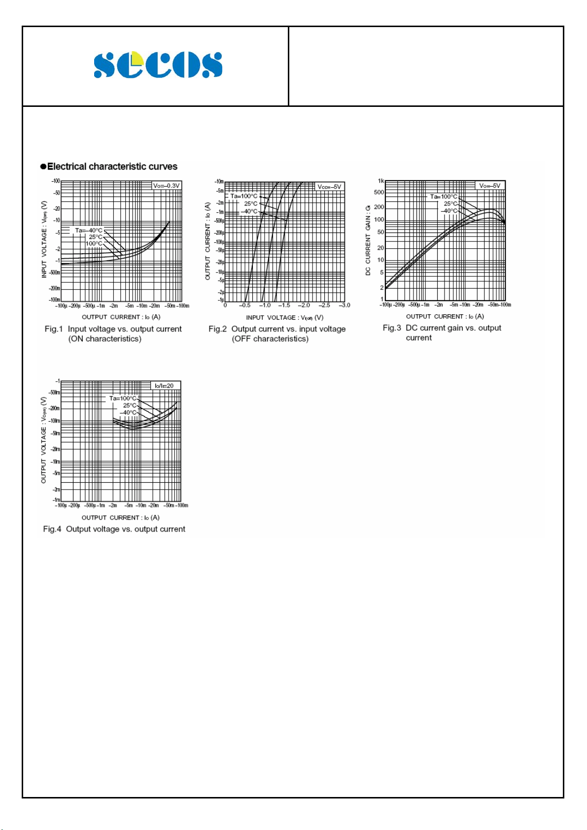
CHARACTERISTIC CURVES
DTA124EE / DTA124EUA / DTA124ECA /
PNP Digital Transistors (Built-in Resistors)
DTA124ESA
http://www.SeCoSGmbH.com/ Any changes of specification will not be informed individually.
11-Aug-2010 Rev. A Page 2 of 2
 Loading...