

Page 1
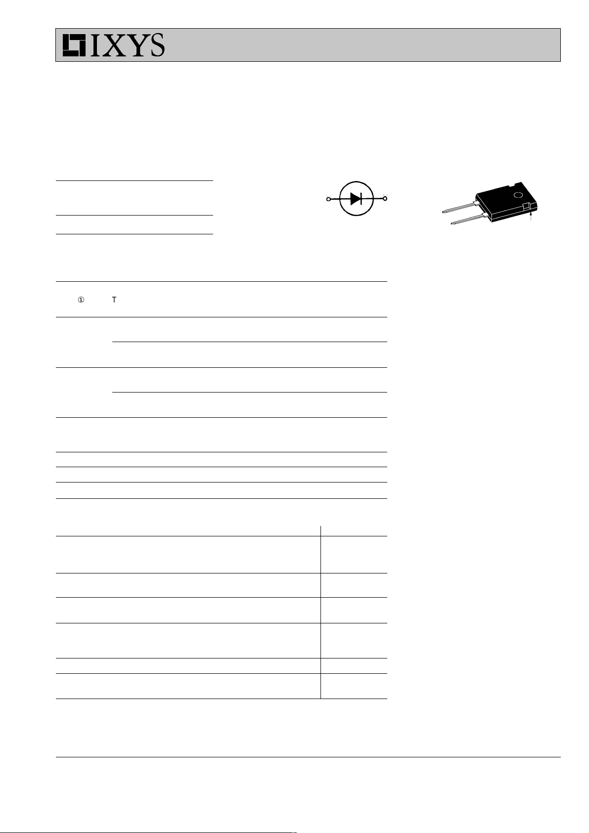
Fast Recovery
Epitaxial Diode (FRED)
V
RSM
V V
200 200 DSEI 60-02A
V
RRM
Type
DSEI 60 I
A
C
RRM
= 69 A
= 200 V
= 35 ns
FAVM
V
t
rr
TO-247 AD
C
A
A = Anode, C = Cathode
C
Symbol Test Conditions Maximum Ratings
I
FRMS
I
ÿÿ
① TC = 85°C; rectangular, d = 0.5 69 A
FAVM
I
FRM
I
FSM
TVJ = T
VJM
tP < 10 ms; rep. rating, pulse width limited by T
VJM
98 A
800 A
TVJ = 45°C; t = 10 ms (50 Hz), sine 600 A
t = 8.3 ms(60 Hz), sine 650 A
TVJ = 150°C; t = 10 ms (50 Hz), sine 540 A
t = 8.3 ms(60 Hz), sine 580 A
Features
●
●
●
●
●
●
●
I2t TVJ = 45°C t = 10 ms (50 Hz), sine 1800 A2s
t = 8.3 ms(60 Hz), sine 1770 A2s
TVJ = 150°C; t = 10 ms (50 Hz), sine 1460 A2s
t = 8.3 ms(60 Hz), sine 1410 A2s
T
VJ
T
VJM
T
stg
P
tot
M
d
TC = 25°C 150 W
Mounting torque 0.8...1.2 Nm
-40...+150 °C
150 °C
-40...+150 °C
Weight 6g
Symbol Test Conditions Characteristic Values
Applications
●
●
●
●
●
●
●
●
typ. max.
I
R
V
F
V
T0
r
T
R
thJC
R
thCK
R
thJA
t
rr
I
RM
TVJ = 25°CVR= V
TVJ = 25°CVR= 0.8 • V
RRM
TVJ = 125°CVR= 0.8 • V
RRM
RRM
50 mA
40 mA
11 mA
IF = 60 A; TVJ=150°C 0.88 V
TVJ= 25°C 1.08 V
For power-loss calculations only 0.70 V
TVJ = T
VJM
4.0 mW
0.75 K/W
0.25 K/W
35 K/W
IF = 1 A; -di/dt = 200 A/ms; VR = 30 V; TVJ = 25°C35 50 ns
VR = 100 V; IF = 60 A; -diF/dt = 200 A/ms 810A
L £ 0.05 mH; TVJ = 100°C
Advantages
●
●
●
●
●
International standard package
JEDEC TO-247 AD
Planar passivated chips
Very short recovery time
Extremely low switching losses
Low IRM-values
Soft recovery behaviour
Epoxy meets UL 94V-0
Antiparallel diode for high frequency
switching devices
Anti saturation diode
Snubber diode
Free wheeling diode in converters
and motor control circuits
Rectifiers in switch mode power
supplies (SMPS)
Inductive heating and melting
Uninterruptible power supplies (UPS)
Ultrasonic cleaners and welders
High reliability circuit operation
Low voltage peaks for reduced
protection circuits
Low noise switching
Low losses
Operating at lower temperature or
space saving by reduced cooling
① I
rating includes reverse blocking losses at T
FAVM
Data according to IEC 60747
IXYS reserves the right to change limits, test conditions and dimensions
, VR = 0.8 V
VJM
, duty cycle d = 0.5
RRM
© 2000 IXYS All rights reserved
036
1 - 2
Page 2
DSEI 60, 200V
160
A
140
120
I
F
100
80
TVJ=150°C
60
TVJ=100°C
40
20
TVJ=25°C
0
0.0 0.4 0.8 1.2
V
F
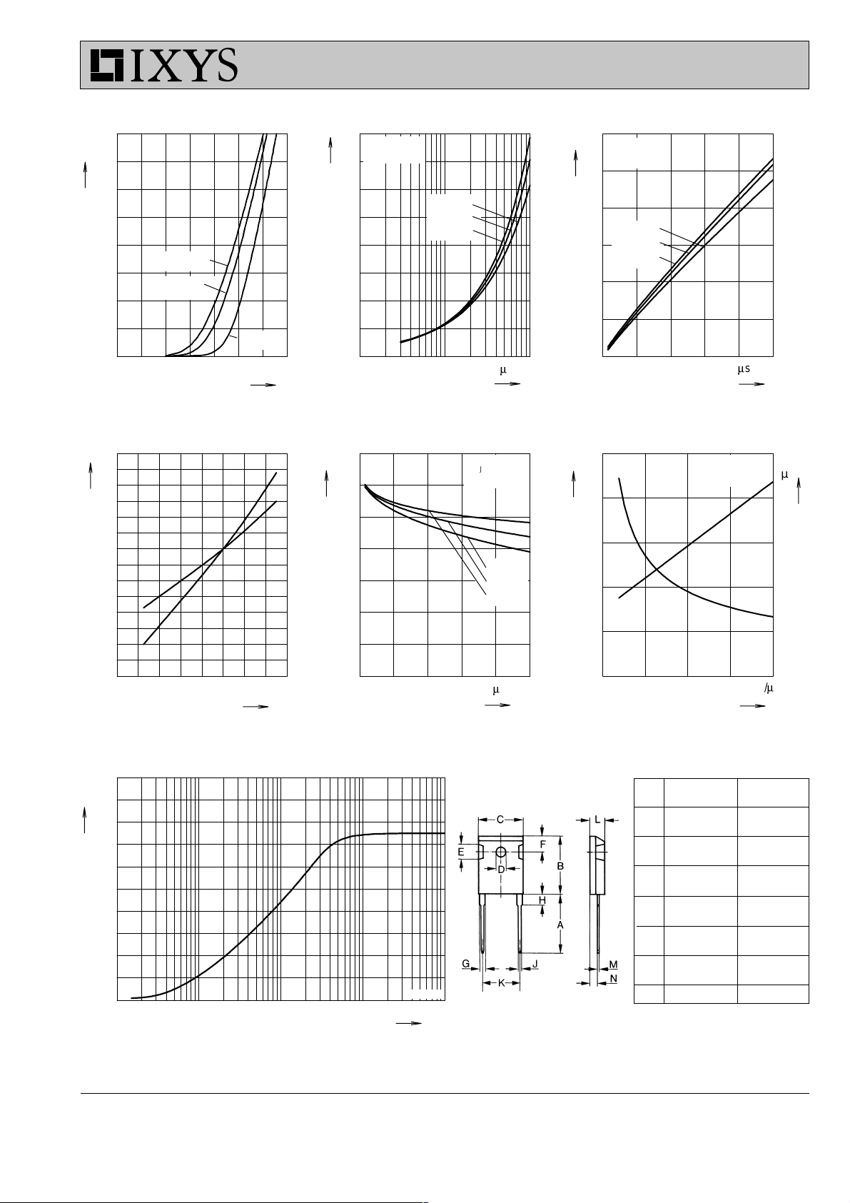
Fig. 1 Forward current IF versus V
1.6
1.4
K
f
1.2
1.0
0.8
0.6
0.4
I
RM
Q
r
Q
r
0.8
µC
0.6
0.4
TVJ= 100°C
VR = 100V
IF= 35A
IF= 70A
IF=140A
I
RM
30
A
25
20
15
TVJ= 100°C
VR = 100V
IF= 35A
IF= 70A
IF=140A
10
0.2
5
0.0
V
10 100 1000
A/ms
-diF/dt
F
Fig. 2 Typ. reverse recovery charge Q
versus -diF/dt
70
ns
60
t
rr
50
TVJ= 100°C
VR = 100V
40
0
200 600 10000 400 800
-di
Fig. 3 Typ. peak reverse current I
r
versus -diF/dt
5
V
4
V
FR
t
fr
3
A/ms
/dt
F
TVJ= 100°C
IF = 100A
V
FR
RM
2.5
µs
2.0
t
fr
1.5
IF=35A
30
IF=70A
IF=140A
2
1.0
20
1
0.5
10
0.2
0 40 80 120 160
T
VJ
Fig. 4 Dynamic parameters Qr, I
versus T
VJ
°C
RM
0
200 600 10000 400 800
Fig. 5 Typ. recovery time t
versus -diF/dt
1.0
K/W
0.8
Z
thJC
0.6
0.4
0.2
0.0
0.001 0.01 0.1 1 10
t
Fig. 7 Transient thermal impedance junction to case
© 2000 IXYS All rights reserved
DSEI 60-02
s
A/ms
-di
/dt
F
rr
Dimensions
0
0 200 400 600 800
diF/dt
Fig. 6 Typ peak forward voltage
VFR and t
Dim. Millimeter Inches
versus diF/dt
fr
Min. Max. Min. Max.
A 19.81 20.32 0.780 0.800
B 20.80 21.46 0.819 0.845
C 15.75 16.26 0.610 0.640
D 3.55 3.65 0.140 0.144
E 4.32 5.49 0.170 0.216
F 5.4 6.2 0.212 0.244
G 1.65 2.13 0.065 0.084
H - 4.5 - 0.177
J 1.0 1.4 0.040 0.055
K 10.8 11.0 0.426 0.433
L 4.7 5.3 0.185 0.209
M 0.4 0.8 0.016 0.031
N 2.2 2.54 0.087 0.102
A/ms
0.0
839
2 - 2
 Loading...