

Page 1
© 2000 IXYS All rights reserved
1 - 2
V
RSM
V
RRM
Type
V V
440 400 DSEI 2x 30-04C DSEI 2x 31-04C
640 600 DSEI 2x 30-06C DSEI 2x 31-06C
Symbol Test Conditions Maximum Ratings (per diode)
I
FRMS
TVJ = T
VJM
70 A
I
FAVM
ÿÿ
① TC = 85°C; rectangular, d = 0.5 30 A
I
FRM
tP < 10 ms; rep. rating, pulse width limited by T
VJM
375 A
I
FSM
TVJ = 45°C; t = 10 ms (50 Hz), sine 300 A
t = 8.3 ms(60 Hz), sine 320 A
TVJ = 150°C; t = 10 ms (50 Hz), sine 260 A
t = 8.3 ms(60 Hz), sine 280 A
I2t TVJ = 45°C t = 10 ms (50 Hz), sine 450 A2s
t = 8.3 ms(60 Hz), sine 420 A2s
TVJ = 150°C; t = 10 ms (50 Hz), sine 340 A2s
t = 8.3 ms(60 Hz), sine 320 A2s
T
VJ
-40...+150 °C
T
VJM
150 °C
T
stg
-40...+150 °C
P
tot
TC = 25°C 100 W
V
ISOL
50/60 Hz, RMS 2500 V~
I
ISOL
£ 1 mA
M
d
Mounting torque 1.5/13 Nm/lb.in.
Terminal connection torque (M4) 1.5/13 Nm/lb.in.
Weight 30 g
Symbol Test Conditions Characteristic Values (per diode)
typ. max.
I
R
TVJ = 25°CVR= V
RRM
100 mA
TVJ = 25°CVR= 0.8 • V
RRM
50 mA
TVJ = 125°CVR= 0.8 • V
RRM
7mA
V
F
IF = 30 A; TVJ=150°C 1.4 V
TVJ=25°C 1.6 V
V
T0
For power-loss calculations only 1.01 V
r
T
TVJ = T
VJM
7.1 mW
R
thJC
1.25 K/W
R
thCK
0.05 K/W
t
rr
IF = 1 A; -di/dt = 100 A/ms; VR = 30 V; TVJ = 25°C35 50 ns
I
RM
VR = 350 V; IF = 30 A; -diF/dt = 240 A/ms1011A
L £ 0.05 mH; TVJ = 100°C
DSEI 2x 30 I
FAVM
= 2x 30 A
DSEI 2x 31 V
RRM
= 400/600 V
t
rr
= 35 ns
① I
FAVM
rating includes reverse blocking losses at T
VJM
, VR = 0.8 V
RRM
, duty cycle d = 0.5
Data according to IEC 60747
IXYS reserves the right to change limits, test conditions and dimensions
DSEI 2x 30 DSEI 2x 31
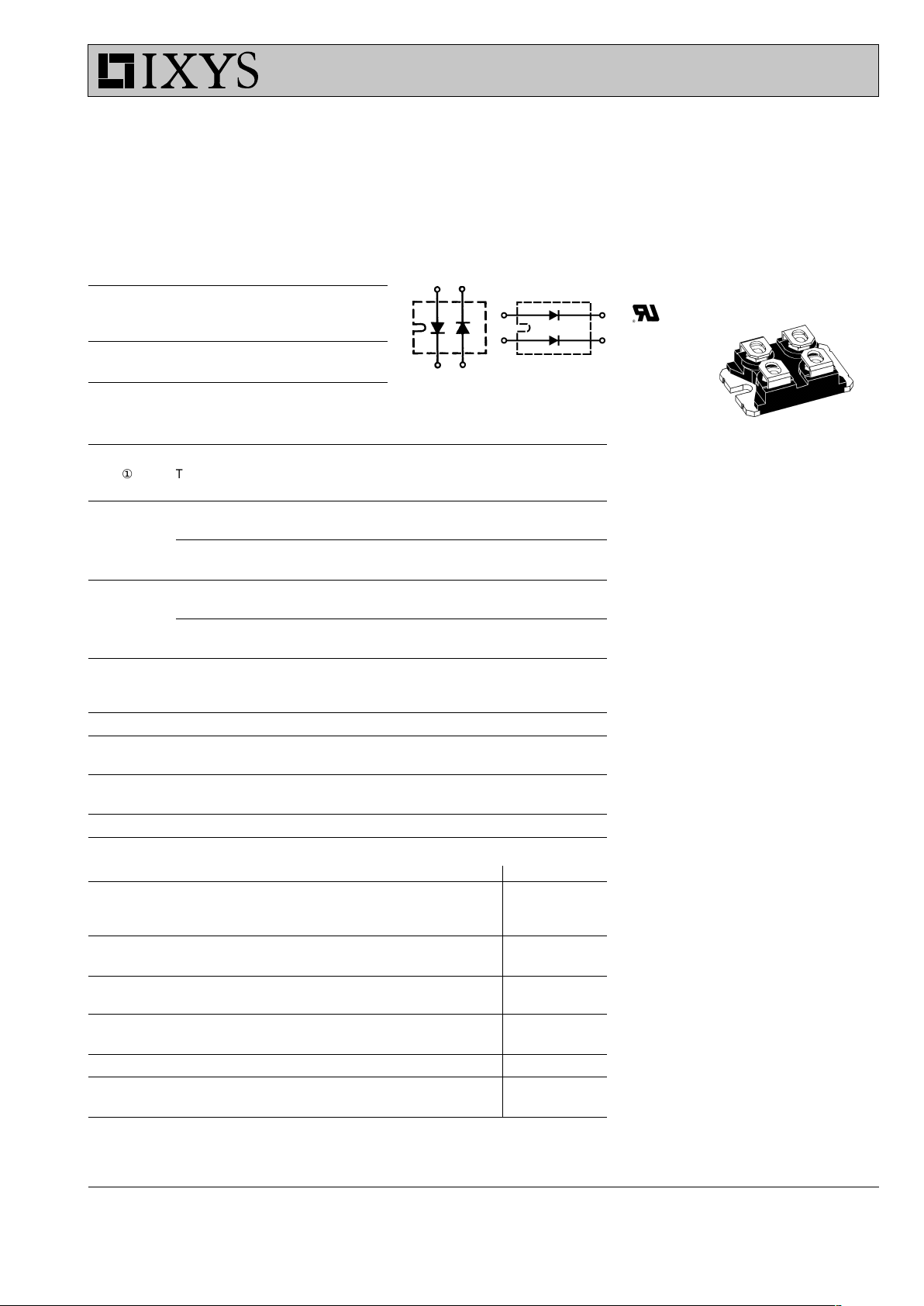
Features
●
International standard package
miniBLOC (ISOTOP compatible)
●
Isolation voltage 2500 V~
●
2 independent FRED in 1 package
●
Planar passivated chips
●
Very short recovery time
●
Extremely low switching losses
●
Low IRM-values
●
Soft recovery behaviour
Applications
●
Antiparallel diode for high frequency
switching devices
●
Anti saturation diode
●
Snubber diode
●
Free wheeling diode in converters
and motor control circuits
●
Rectifiers in switch mode power
supplies (SMPS)
●
Inductive heating and melting
●
Uninterruptible power supplies (UPS)
●
Ultrasonic cleaners and welders
Advantages
●
High reliability circuit operation
●
Low voltage peaks for reduced
protection circuits
●
Low noise switching
●
Low losses
●
Operating at lower temperature or
space saving by reduced cooling
Fast Recovery
Epitaxial Diode (FRED)
miniBLOC, SOT-227 B
E72873
009
Page 2
© 2000 IXYS All rights reserved
2 - 2
DSEI 2x 30, 400/600 V
DSEI 2x 31, 400/600 V
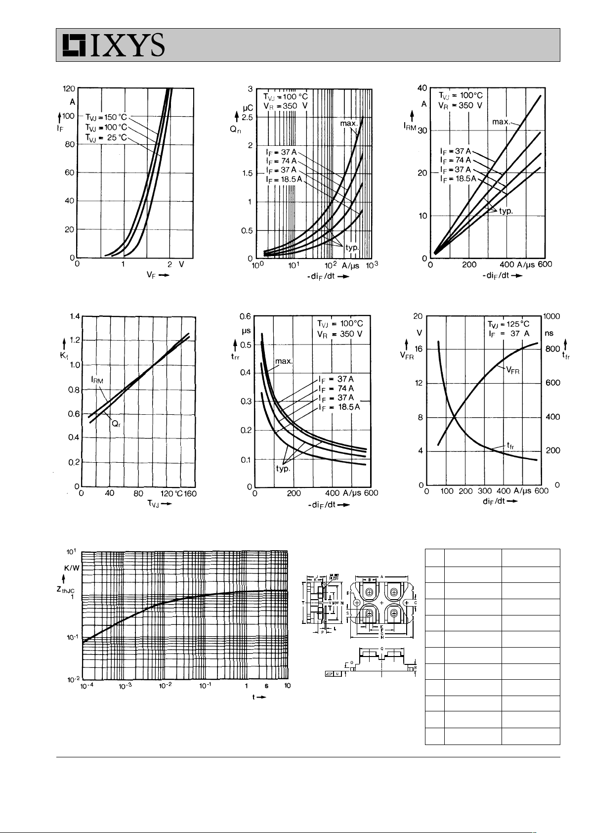
Fig. 1 Forward current Fig. 2 Recovery charge versus -diF/dt. Fig. 3 Peak reverse current versus
versus voltage drop. -diF/dt.
Fig. 4 Dynamic parameters versus Fig. 5 Recovery time versus -diF/dt. Fig. 6 Peak forward voltage
junction temperature. versus diF/dt.
Fig. 7 Transient thermal impedance junction to case.
Dim. Millimeter Inches
Min. Max. Min. Max.
A 31.50 31.88 1.240 1.255
B 7.80 8.20 0.307 0.323
C 4.09 4.29 0.161 0.169
D 4.09 4.29 0.161 0.169
E 4.09 4.29 0.161 0.169
F 14.91 15.11 0.587 0.595
G 30.12 30.30 1.186 1.193
H 37.80 38.20 1.489 1.505
J 11.68 12.22 0.460 0.481
K 8.92 9.60 0.351 0.378
L 0.76 0.84 0.030 0.033
M 12.60 12.85 0.496 0.506
N 25.15 25.42 0.990 1.001
O 1.98 2.13 0.078 0.084
P 4.95 5.97 0.195 0.235
Q 26.54 26.90 1.045 1.059
R 3.94 4.42 0.155 0.174
S 4.72 4.85 0.186 0.191
T 24.59 25.07 0.968 0.987
U -0.05 0.1 -0.002 0.004
V 3.30 4.57 0.130 0.180
W 0.780 0.830 19.81 21.08
Dimensions
miniBLOC SOT-227 B
M4 screws (4x) supplied
 Loading...