

Page 1
DS8935
LocalTalk
™
Dual Driver/Triple Receiver
General Description
The DS8935 is a dual driver/triple receiver device optimized
to provide a single chip solution for a LocalTalk Interface.
The device provides one differential TIA/EIA-422 driver,one
TIA/EIA-423 single ended driver, one TIA/EIA-422 receiver
and two TIA/EIA-423receivers, all in a surface mount 16-pin
package. This device is electrically similar to the 26LS30 and
26LS32 devices.
The drivers feature
±
10V common mode range, and the differential driver provides TRI-STATEable outputs. The receivers offer
±
200 mV thresholds over the±10V common mode
range.
The device offers enable circuitry for the differential driver
and selectable enabling for the three receivers.
Features
n Single chip solution for LocalTalk port
n Two driver/three receivers per package
n Wide common mode range:
±
10V
n
±
200 mV receiver sensitivity
n 70 mV typical receiver input hysteresis
n Available in SOIC packaging
n Failsafe receiver for open inputs
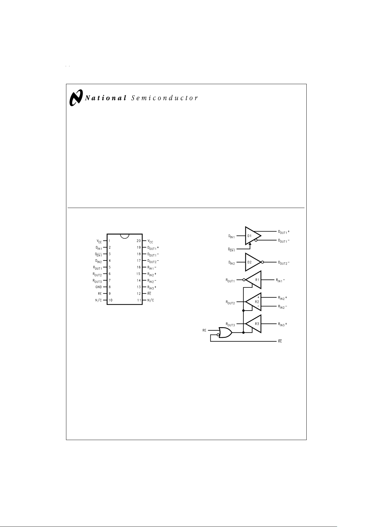
Connection Diagram Functional Diagram
TRI-STATE®is a registered trademark of National Semiconductor Corporation.
LocalTalk
™
is a trademark of Apple Computer, Inc.
Dual-In-Line Package
DS012066-1
Order Number DS8935WM
See NS Package Number M20B
DS012066-2
February 1996
DS8935 LocalTalk Dual Driver/Triple Receiver
© 1998 National Semiconductor Corporation DS012066 www.national.com
Page 2
Absolute Maximum Ratings (Note 1)
If Military/Aerospace specified devices are required,
please contact the National Semiconductor Sales Office/
Distributors for availability and specifications.
Supply Voltage (V
CC
) +7V
Supply Voltage (V
EE
) −7V
Enable Input Voltage (D
EN1
, RE, RE ) +7V
Driver Input Voltage (D
IN
) +7V
Driver Output Voltage (Power Off: D
OUT
)
±
15V
Receiver Input Voltage (V
ID:RIN
+−RIN−)
±
25V
Receiver Input Voltage (V
CM
:(RIN++RIN−)/2)
±
25V
Receiver Input Voltage (Input to GND: R
IN
)
±
25V
Receiver Output Voltage (R
OUT
) +5.5V
Maximum Package Power Dissipation
@
+25˚C
M Package 1.34W
Derate M Package 10.7 mW/˚C above +25˚C
Storage Temperature Range −65˚C to
+150˚C
Lead Temperature Range (Soldering, 4 Sec.) +260˚C
This device does not meet 2000V ESD Rating (Note 8)
Recommended Operating
Conditions
Min Typ Max Units
Supply Voltage (V
CC
) +4.75 +5.0 +5.25 V
Supply Voltage (V
EE
) −4.75 −5.0 −5.25 V
Operating Free Air
Temperature (T
A
) 0 25 70 ˚C
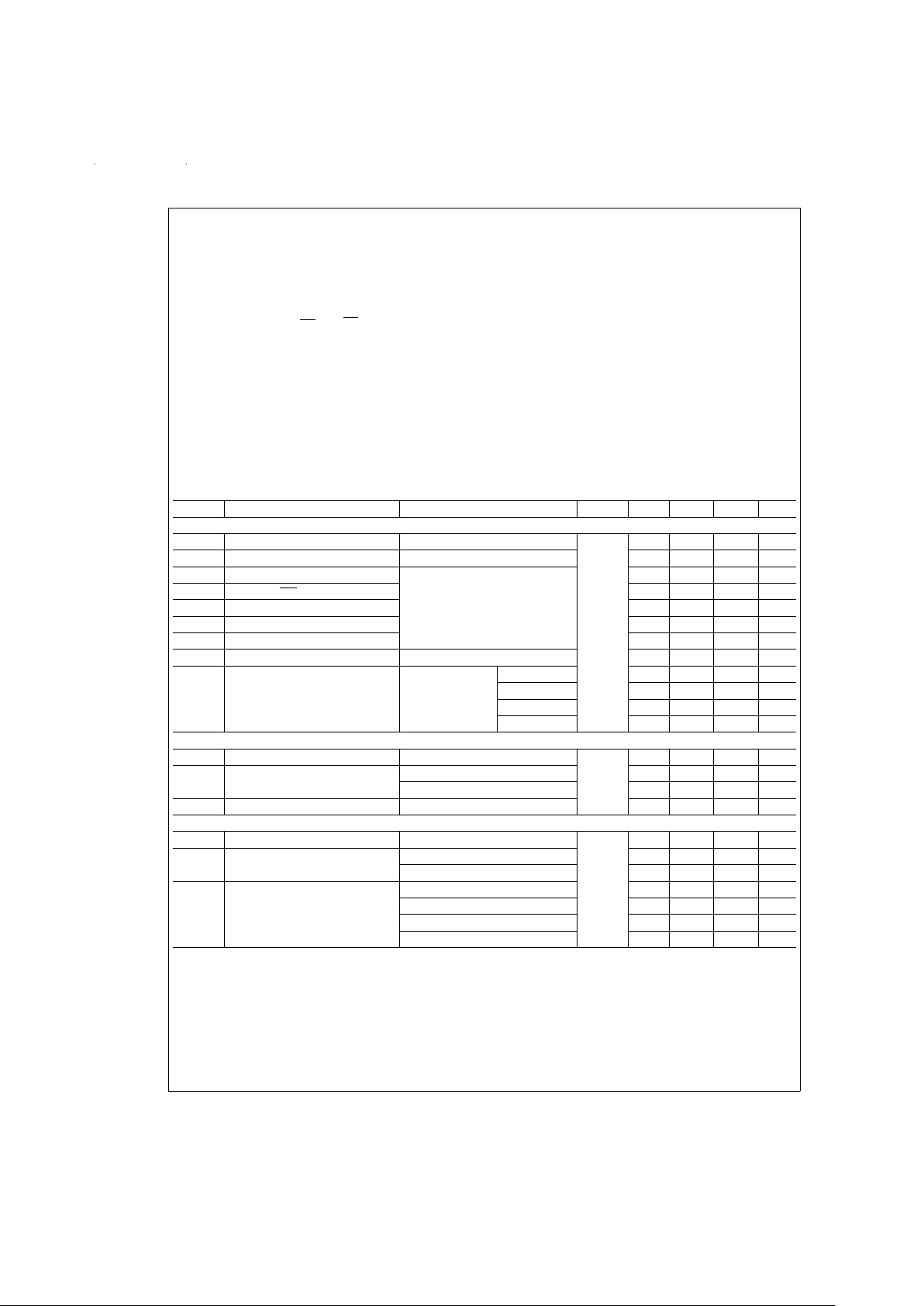
Electrical Characteristics (Notes 2, 3)
Over Supply Voltage and Operating Temperature ranges, unless otherwise specified
Symbol Parameter Conditions Pin Min Typ Max Units
DIFFERENTIAL DRIVER CHARACTERISTICS
V
OD
Output Differential Voltage R
L
=
∞
or R
L
=
3.9 kΩ
D
OUT
+,
D
OUT
−
±
7
±
9.0
±
10 V
V
O
Output Voltage R
L
=
∞
or R
L
=
3.9 kΩ
±
4.5±5.25 V
V
OD1
Output Differential Voltage R
L
=
100Ω,
Figure 1
4.0 6.4 |V|
V
SS
|V
OD1−VOD1
| 8.0 12.8 |V|
∆V
OD1
Output Unbalance 0.02 0.4 V
V
OS
Offset Voltage 03V
∆V
OS
Offset Unbalance 0.05 0.4 V
V
OD2
Output Differential Voltage RL=140Ω,
Figure 1
6.0 7.0 |V|
I
OZD
TRI-STATE®Leakage Current V
CC
=
5.25V V
O
=
+10V 2 150 µA
V
EE
=
−5.25V V
O
=
+6V 1 100 µA
V
O
=
−6V −1 −100 µA
V
O
=
−10V −2 −150 µA
SINGLE ENDED DRIVER CHARACTERISTICS
V
O
Output Voltage (No Load) R
L
=
∞
or R
L
=
3.9 kΩ,
Figure 2
D
OUT
−
4 4.4 6 |V|
V
T
Output Voltage R
L
=
3kΩ,
Figure 2
3.7 4.3 |V|
R
L
=
450Ω,
Figure 2
3.6 4.1 |V|
∆V
T
Output Unbalance 0.02 0.4 V
DRIVER CHARACTERISTICS
V
CM
Common Mode Range Power Off, or D1 Disabled
D
OUT
+,
D
OUT
−
±
10 V
I
OSD
Short Circuit Current V
O
=
0V, Sourcing Current −80 −150 mA
V
O
=
0V, Sinking Current 80 150 mA
I
OXD
Power-Off Leakage Current V
O
=
+10V 2 150 µA
(V
CC
=
V
EE
=
0V) V
O
=
+6V 1 100 µA
V
O
=
−6V −1 −100 µA
V
O
=
−10V −2 −150 µA
www.national.com 2
Page 3
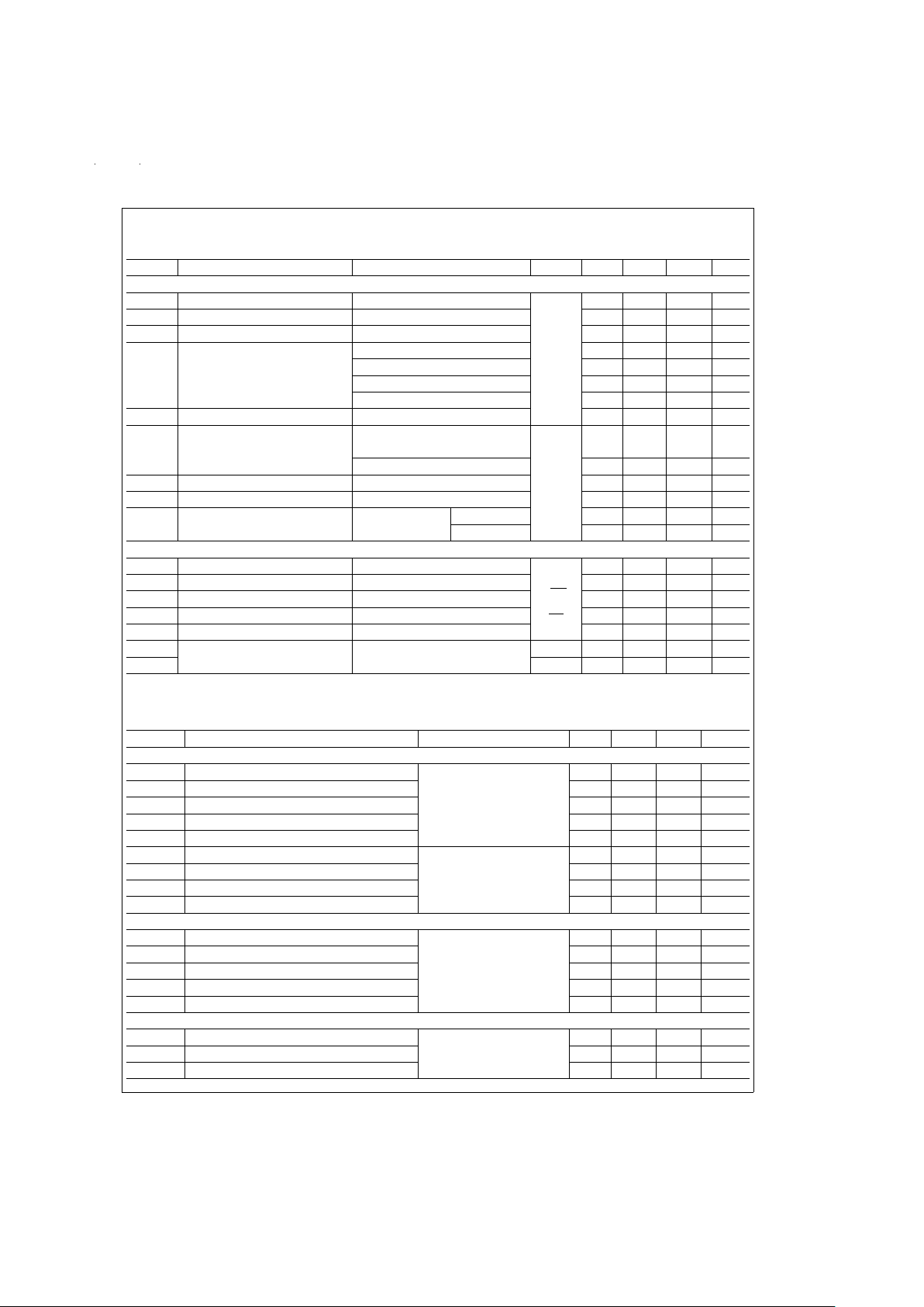
Electrical Characteristics (Notes 2, 3) (Continued)
Over Supply Voltage and Operating Temperature ranges, unless otherwise specified
Symbol Parameter Conditions Pin Min Typ Max Units
RECEIVER CHARACTERISTICS
V
TH
Input Threshold −7V ≤ VCM≤ +7V
R
IN
+,
R
IN
−
−200
±
35 +200 mV
V
HY
Hysteresis V
CM
=
0V 70 mV
R
IN
Input Resistance −10V ≤ VCM≤ +10V 6.0 8.5 kΩ
I
IN
Input Current (Other Input=0V, V
IN
=
+10V 3.25 mA
Power On, or V
CC
=
V
EE
=
0V) V
IN
=
+3V 0 1.50 mA
V
IN
=
−3V 0 −1.50 mA
V
IN
=
−10V −3.25 mA
V
IB
Input Balance Test R
S
=
500Ω (R2 only)
±
400 mV
V
OH
High Level Output Voltage I
OH
=
−400 µA,
R
OUT
2.7 4.2 V
V
IN
=
+200 mV
I
OH
=
−400 µA, V
IN
=
OPEN 2.7 4.2 V
V
OL
Low Level Output Voltage I
OL
=
8.0 mA, V
IN
=
−200 mV 0.3 0.5 V
I
OSR
Short Circuit Current V
O
=
0V −15 −34 −85 mA
I
OZR
TRI-STATE Output Current V
CC
=
Max V
O
=
2.4V 0 +20 µA
V
O
=
0.4V 0 −20 µA
DEVICE CHARACTERISTICS
V
IH
High Level Input Voltage
D
IN
,
D
EN1
,
RE,
RE
2.0 V
V
IL
Low Level Input Voltage 0.8 V
I
IH
High Level Input Current V
IN
=
2.4V 1 40 µA
I
IL
Low Level Input Current V
IN
=
0.4V −10 −200 µA
V
CL
Input Clamp Voltage I
IN
=
−12 mA −1.5 V
I
CC
Power Supply Current No Load
D1 Enabled or Disabled
V
CC
40 65 mA
I
EE
V
EE
−5 −15 mA
Switching Characteristics (Notes 4, 5)
Over Supply Voltage and Operating Temperature Ranges, unless otherwise specified
Symbol Parameter Conditions Min Typ Max Units
DIFFERENTIAL DRIVER CHARACTERISTICS
t
PHLD
Differential Propagation Delay High to Low R
L
=
100Ω,C
L
=
500 pF,
(
Figures 3, 4
)
C
1
=
C
2
=
50 pF
70 134 350 ns
t
PLHD
Differential Propagation Delay Low to High 70 141 350 ns
t
SKD
Differential Skew |t
PHLD−tPLHD
| 7 50 ns
t
r
Rise Time 50 140 300 ns
t
f
Fall Time 50 140 300 ns
t
PHZ
Disable Time High to Z R
L
=
100Ω,C
L
=
500 pF
(
Figures 7, 8
)
300 600 ns
t
PLZ
Disable Time Low to Z 300 600 ns
t
PZH
Enable Time Z to High 160 350 ns
t
PZL
Enable Time Z to Low 160 350 ns
SINGLE ENDED DRIVER CHARACTERISTICS
t
PHL
Propagation Delay High to Low R
L
=
450Ω,C
L
=
500 pF
(
Figures 5, 6
)
70 120 350 ns
t
PLH
Propagation Delay Low to High 70 150 350 ns
t
SK
Skew, |t
PHL−tPLH
30 70 ns
t
r
Rise Time 50 100 300 ns
t
f
Fall Time 20 50 300 ns
RECEIVER CHARACTERISTICS
t
PHL
Propagation Delay High to Low C
L
=
15 pF
(
Figures 9, 10
)
10 33 75 ns
t
PLH
Propagation Delay Low to High 10 30 75 ns
t
SK
Skew, |t
PHL−tPLH
| 320ns
www.national.com3
Page 4
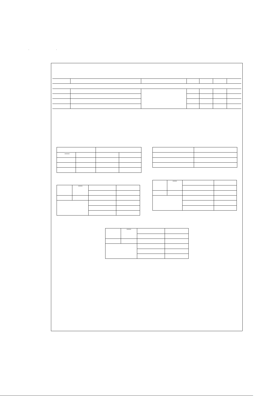
Switching Characteristics (Notes 4, 5) (Continued)
Over Supply Voltage and Operating Temperature Ranges, unless otherwise specified
Symbol Parameter Conditions Min Typ Max Units
RECEIVER CHARACTERISTICS
t
HZ
Disable Time High to Z C
L
=
15 pF
(
Figures 9, 11
)
20 75 ns
t
LZ
Disable Time Low to Z 20 75 ns
t
ZH
Enable Time Z to High 20 75 ns
t
ZL
Enable Time Z to Low 20 75 ns
Note 1: Absolute Maximum Ratings are those values beyond which the safety of the device cannot be guaranteed. They are not meant to imply that the devices
should be operated at these limits. The table of Electrical Characteristics specifies conditions of device operation.
Note 2: Current into device pins is defined as positive. Current out of device pins is defined as negative. All voltages are referenced to ground except V
OD,VOD1
,
V
OD2
, and VSS.
Note 3: All typicals are given for: V
CC
=
+5.0V, V
EE
=
−5.0V, T
A
=
+25˚C unless otherwise specified.
Truth Tables
Driver (D1)
Inputs Outputs
D
EN1
D
IN1
D
OUT1
+D
OUT1
−
HX Z Z
LL L H
LH H L
Receiver (1)
RE RE Input Output
R
IN1
−R
OUT1
01 X Z
Any Other ≤−200 mV H
Combination ≥+200 mV L
Open
†
H
Driver (D2)
Input Output
D
IN2
D
OUT2
−
LH
HL
Receiver (2)
RE RE Inputs Output
R
IN2
+–R
IN2
−R
OUT2
01 X Z
Any Other ≤−200 mV L
Combination ≥+200 mV H
Open
†
H
Receiver (3)
RE RE Input Output
R
IN3
+R
OUT3
01 X Z
Any Other ≤−200 mV L
Combination ≥+200 mV H
Open
†
H
H=Logic High Level (Steady State)
L=Logic Low Level (Steady State)
X=Irrelevant (Any Input)
Z=Off State (TRI-STATE,High Impedance)
†
OPEN=Non-Terminated
www.national.com 4
Page 5

Parameter Measurement Information
DS012066-3
FIGURE 1. Differential Driver DC Test Circuit
DS012066-4
FIGURE 2. Single Ended Driver DC Test Circuit
DS012066-5
FIGURE 3. Differential Driver Propagation Delay and Transition Time Test Circuit
DS012066-6
FIGURE 4. Differential Driver Propagation Delay and Transition Time Waveforms
DS012066-7
FIGURE 5. Single Ended Driver Propagation Delay and Transition Time Test Circuit
www.national.com5
Page 6

Parameter Measurement Information (Continued)
DS012066-8
FIGURE 6. Single Ended Driver Propagation Delay and Transition Time Waveform
DS012066-9
FIGURE 7. Differential Driver TRI-STATE Test Circuit
DS012066-10
FIGURE 8. Differential Driver TRI-STATE Waveforms
DS012066-11
FIGURE 9. Receiver Propagation Delay Test Circuit
DS012066-12
FIGURE 10. Receiver Propagation Delay Waveform
www.national.com 6
Page 7

Parameter Measurement Information (Continued)
Note 4: Generator waveform for all tests unless otherwise specified: f=500 kHz, Z
O
=
50Ω,t
r
≤10 ns, tf≤ 10 ns.
Note 5: C
L
includes probe and jig capacitance.
Note 6: All diodes are 1N916 or equivalent.
Note 7: S1 and S2 closed except where shown.
Note 8: ESD Rating HBM (1.5 kΩ, 100 pF) pins 14, 16 ≥1500V, all other pins ≥2000V.
Typical Application Information
DS012066-13
FIGURE 11. Receiver TRI-STATE Delay Waveform
DS012066-14
FIGURE 12. Typical LocalTalk Application
www.national.com7
Page 8

Typical Application Information (Continued)
TABLE 1. Device Pin Descriptions
Pin
#
Name Description
2, 4 D
IN
TTL Driver Input Pins
3D
EN1
Active Low Driver Enable Pin. A High on this Pin TRI-STATEs the Driver
Outputs (D1 Only)
19 D
OUT
+ Non-Inverting Driver Output Pin
17, 18 D
OUT
− Inverting Driver Output Pin
13, 15 R
IN
+ Non-Inverting Receiver Input Pin
16, 14 R
IN
− Inverting Receiver Input Pin
5, 6, 7 R
OUT
Receiver Output Pin
9R
EN
Active Low Receiver Enable
12 R
EN
Active High Receiver Enable
10, 11 N/C Not Connected
8 GND Ground Pin
1V
EE
Negative Power Supply Pin, −5V±5
%
20 V
CC
Positive Power Supply Pin, +5V±5
%
DRIVER OUTPUT WAVEFORMS
The driver configuration on the DS8935 is unique among
TIA/EIA-422 devices in that it utilizes −5V V
EE
supply.Atypical TIA/EIA-422 driver uses +5V only and generates signal
swings of approximately 0V–5V.
By utilizing V
EE
, the differential driver is able to generate a
much larger differential signal. The typical output voltage is
about |4| V, which gives |8| V differentially, thus providing a
much greater noise margin than +5V drivers. See
Figure 13
.
The receiver therefore has a range of +8V to −8V or V
SS
of
16V (V
SS
=
V
OD–VOD
*
).
Each side of the differential driver operates similar to a TIA/
EIA-423 driver. The output voltages are slightly different due
to the loading: the differential driver has differential termination, the single-ended driver is terminated with a resistor to
ground.
DS012066-15
DS012066-16
Note 9: V
CC
=
+5V, V
EE
=
−5V
Note 10: D1 Enabled (Active)
FIGURE 13. Typical Driver Output Waveforms
www.national.com 8
Page 9

Typical Application Information
(Continued)
UNUSED PINS
Unused driver outputs should be left open. If tied to either
ground or supply, the driver may enter an I
OS
state and consume excessive power. Unused driver inputs should not be
left floating as this may lead to unwanted switching which
may affect I
CC
, particularly the frequency component. Un-
used driver inputs should be tied to ground.
Receiver outputs will be in a HIGH state when inputs are
open; therefore, outputs should not be tied to ground. It is
best to leave unused receiver outputs floating.
RECEIVER FAILSAFE
All three receivers on this device incorporate open input failsafe protection. The differential receiver output will be in a
HIGH state when inputs are open, but will be indetermined if
inputs are shorted together. Unused differential inputs
should be left floating.
Both single-ended receivers (inverting and non-inverting) are
biased internally so that an open input will result in a HIGH
output. Therefore, these inputs should not be shorted to
ground when unused.
BYPASS CAPACITORS
Bypass capacitors are recommended for both V
CC
and VEE.
Noise induced on the supply lines can affect the signal quality of the output; V
CC
affects the VOHand VEEaffects the
V
OL
. Capacitors help reduce the effect on signal quality. A
value of 0.1 µF is typically used.
Since this is a power device, it is recommended to use a bypass capacitor for each supply and for each device. Sharing
a bypass capacitor between other devices may not be sufficient.
TERMINATION
On a multi-point transmission line which is electrically long, it
is advisable to terminate the line at both ends with its characteristic impedance to prevent signal reflection and its associated noise/crosstalk.
A 100Ω termination resistor is commonly specified by TIA/
EIA-422 for differential signals. The DS8935 is also specified
using 140Ω termination which will result in less power associated with the driver output. The additional resistance is
typical of applications requiring EMI filtering on the driver
outputs.
TWO-WIRE LocalTalk
The DS8935 is a single chip solution for a LocalTalk interface. A typical application is shown in
Figure 12
.
An alternative implementation of LocalTalk is to only use two
wires to communicate. The differential data lines can be
transformer-coupled on to a twisted pair medium. See
Figure
14
. The handshake function must then be accomplished in
software.
SINGLE +5V SUPPLY
The DS8935 is derived from the DS3691/92 which could be
configured using a single +5V supply (V
EE
=
0V). This device
is not specified for this type of operation. However, the device will not be damaged if operated using a single +5V supply.
Both drivers require the −5V supply in order to meet the output voltage levels specified. When the device switches from
a positive voltage to the complimentary state, it is pulled toward the V
EE
level. If that level is 0V, then the complimentary
state will be near 0V instead of V
EE
. Thus, the output would
switch from about 4V to 0V, instead of 4V to −4V.The differential driver will meet TIA/EIA-422, but with a reduced noise
margin. The single-ended driver will not meet TIA/EIA-423
without the −5V supply.
The receivers will be functional but may suffer parametrically. The inverting receiver is referenced to V
EE
therefore,
the threshold may shift slightly. The inputs can still vary over
the
±
10V common mode range.
DS012066-17
FIGURE 14. Differential Communication, Transformer-Coupled to a Twisted-Pair Line
www.national.com9
Page 10

Typical Application Information (Continued)
Typical Performance Characteristics
The DS8935 is very closely related to the DS8925. Please refer to the DS8925 datasheet for the typical performance characteristics.
DS012066-48
FIGURE 15. Driver Output Structure
DS012066-49
FIGURE 16. Receiver Input Structure
www.national.com 10
Page 11

11
Page 12

Physical Dimensions inches (millimeters) unless otherwise noted
LIFE SUPPORT POLICY
NATIONAL’S PRODUCTS ARE NOT AUTHORIZED FOR USE AS CRITICAL COMPONENTS IN LIFE SUPPORT DEVICES OR SYSTEMS WITHOUT THE EXPRESS WRITTEN APPROVAL OF THE PRESIDENT OF NATIONAL SEMICONDUCTOR CORPORATION. As used herein:
1. Life support devices or systems are devices or systems which, (a) are intended for surgical implant into
the body, or (b) support or sustain life, and whose failure to perform when properly used in accordance
with instructions for use provided in the labeling, can
be reasonably expected to result in a significant injury
to the user.
2. A critical component in any component of a life support
device or system whose failure to perform can be reasonably expected to cause the failure of the life support
device or system, or to affect its safety or effectiveness.
National Semiconductor
Corporation
Americas
Tel: 1-800-272-9959
Fax: 1-800-737-7018
Email: support@nsc.com
www.national.com
National Semiconductor
Europe
Fax: +49 (0) 1 80-530 85 86
Email: europe.support@nsc.com
Deutsch Tel: +49 (0) 1 80-530 85 85
English Tel: +49 (0) 1 80-532 78 32
Français Tel: +49 (0) 1 80-532 93 58
Italiano Tel: +49 (0) 1 80-534 16 80
National Semiconductor
Asia Pacific Customer
Response Group
Tel: 65-2544466
Fax: 65-2504466
Email: sea.support@nsc.com
National Semiconductor
Japan Ltd.
Tel: 81-3-5620-6175
Fax: 81-3-5620-6179
20-Lead (0.300" Wide) Molded Small Outline Package, JEDEC
Order Number DS8935WM
NS Package Number M20B
DS8935 LocalTalk Dual Driver/Triple Receiver
National does not assume any responsibility for use of any circuitry described, no circuit patent licenses are implied and National reserves the right at any time without notice to change said circuitry and specifications.
 Loading...