

Page 1

Technical Datasheet DS45
Introduction
Luxeon®III is a revolutionary, energy efficient and ultra compact new light
source, combining the lifetime and reliability advantages of Light Emitting
Diodes with the brightness of conventional lighting.
Luxeon III is rated for up to 1400mA operation, delivering increased lumens
per package.
Luxeon Emitters give you total design freedom and unmatched brightness,
creating a new world of light.
Luxeon Emitters can be purchased in reels for high volume assembly.
For more information, consult your local Lumileds representative.
For high volume applications, custom Luxeon power light source designs
are available upon request, to meet your specific needs.
Luxeon III Emitter
Features
Highest flux per LED family
in the world
Very long operating life (up to
100k hours)
Available in 5500K white,
green, blue, royal blue, cyan,
red, redorange, and amber
Lambertian and side emitting
radiation patterns
More energy efficient than
incandescent and most
halogen lamps
Low voltage DC operated
Cool beam, safe to the touch
Instant light (less than 100 ns)
Fully dimmable
No UV
Superior ESD protection
Typical Applications
Reading lights (car, bus, aircraft)
Portable (flashlight, bicycle)
Miniaccent/Uplighters/
Downlighters/Orientation
Fiber optic alternative/
Decorative/Entertainment
Bollards/Security/Garden
Cove/Undershelf/Task
Automotive rear combination
lamps
Traffic signaling/Beacons/ Rail
crossing and Wayside
Indoor/Outdoor Commercial
and Residential Architectural
Edgelit signs (Exit, point of sale)
LCD Backlights/Light Guides
power light source
查询LXHL-DB09供应商
Page 2

Luxeon III Emitter DS45 (3/05)
2
Mechanical Dimensions
Lambertian
Notes:
1.The anode side of the device is denoted by a hole in the lead frame. Electrical insulation between the case and the board is
required—slug of device is not electrically neutral. Do not electrically connect either the anode or cathode to the slug.
2.All dimensions are in millimeters.
3.All dimensions without tolerances are for reference only.
Side Emitting
Notes:
1.The anode side of the device is denoted by a hole in the lead frame. Electrical insulation between the case and the board is
required—slug of device is not electrically neutral. Do not electrically connect either the anode or cathode to the slug.
2.Caution must be used in handling this device to avoid damage to the lens surfaces that will reduce optical efficiency.
3.All dimensions are in millimeters.
4.All dimensions without tolerances are for reference only.
Drawings not to scale
Drawings not to scale
Page 3

Flux Characteristics at 700mA, Junction Temperature, TJ= 25ºC
Table 1.
MMiinniimmuumm LLuummiinnoouuss TTyyppiiccaall LLuummiinnoouuss
FFlluuxx ((llmm)) oorr FFlluuxx ((llmm)) oorr
RRaaddiioommeettrriicc RRaaddiioommeettrriicc
LLuuxxeeoonn PPoowweerr ((mmWW)) PPo
owweerr ((mmWW)) RRaaddiiaattiioonn
CCoolloorr EEmmiitttteerr ΦΦ
V
[1,2]
ΦΦ
V
[2]
PPaatttteerrnn
White LXHLPW09 60.0 65
Green LXHLPM09 51.7 64 Lambertian
Cyan LXHLPE09 51.7 64
Blue
[3]
LXHLPB09 13.9 23
Royal Blue
[4]
LXHLPR09 275 mW 340 mW
White LXHLDW09 51.7 58
Green LXHLDM09 51.7 58 Side Emitting
Blue
[3]
LXHLDB09 13.9 21
Flux Characteristics at 1000mA, Junction Temperature, TJ= 25ºC
Table 2.
TTyyppiiccaall LLuummiinnoouuss FFlluuxx ((llmm))
oorr RRaaddiioommeettrriicc PPoowweerr ((mmWW))
LLuuxxeeoonn ΦΦ
V
[1,2]
RRaaddiiaattiioonn
CCoolloorr EEmmiitttteerr 11000000 mmAA PPaatttteerrnn
White LXHLPW09 80
Green LXHLPM09 80 Lambertian
Cyan LXHLPE09 80
Blue
[3]
LXHLPB09 30
Royal Blue
[4]
LXHLPR09 450 mW
White LXHLDW09 70
Green LXHLDM09 70 Side Emitting
Blue
[3]
LXHLDB09 27
Notes for Tables 1 & 2:
1.Minimum luminous flux or radiometric power performance guaranteed within published operating conditions. Lumileds main
tains a tolerance of ± 10% on flux and power measurements.
2.Luxeon types with even higher luminous flux levels will become available in the future. Please consult your Lumileds Authorized
Distributor or Lumileds sales representative for more information.
3.Typical flux value for 470nm devices. Due to the CIE eye response curve in the short blue wavelength range, the minimum
luminous flux will vary over the Lumileds blue color range. Luminous flux will vary from a typical of 17lm for the 460465nm bin
to a typical of 30lm for the 475480 nm bin due to this effect. Although the luminous power efficiency is lower in the short blue
wavelength range, radiometric power efficiency increases as wavelength decreases. For more information, consult the Luxeon
Design Guide, available upon request.
4.Royal Blue product is binned by radiometric power and peak wavelength rather than photometric lumens and dominant
wavelength.
Luxeon III Emitter DS45 (3/05)
3
Page 4

Luxeon III Emitter DS45 (3/05)
4
Flux Characteristics at 1400mA, Junction Temperature, TJ= 25ºC
Table 3.
MMiinniimmuumm LLuummiinnoouuss TTyyppiiccaall LLuummiinnoouuss
LLuuxxeeoonn FFlluuxx ((llmm)) FFlluuxx ((llmm)) RRaaddiiaattiioonn
CCoolloorr EEmmiitttteerr FF
V
[1,2]
FF
V
[2]
PPaatttteerrnn
Red LXHLPD09 90 140
RedOrange LXHLPH09 120 190 Lambertian
Amber LXHLPL09 70 110
Red LXHLDD09 90 125
RedOrange LXHLDH09 120 170 Side Emitting
Amber LXHLDL09 70 100
Notes for Table 3:
1.Minimum luminous flux performance guaranteed within published operating conditions. Lumileds maintains a
tolerance of ± 10% on flux measurements.
2.Luxeon types with even higher luminous flux levels will become available in the future. Please consult your Lumileds Authorized
Distributor or Lumileds sales representative for more information.
Page 5

5
Luxeon III Emitter DS45 (3/05)
Optical Characteristics at 700mA, Junction Temperature, TJ= 25ºC
Table 4.
DDoommiinnaanntt WWaavveelleennggtthh
[[11]]
TTeemmppeerraattuurree
λλDD,, CCooeeffffiicciieenntt ooff TToottaall
PPeeaakk WWaavveelleennggtthh
[[22]]
λλPP,, SSppeeccttrraall DDoommiinnaanntt IInncclluuddeedd VViieewwiinngg
oorr CCoolloorr TTeemmppeerraattuurree
[[33]]
HHaallffwwiiddtthh
[[44]]
WWaavveelleennggtthh AAnnggllee
[[55]]
AAnnggllee
[[66]]
RRaaddiiaattiioonn CCCCTT ((nnmm)) ((nnmm//ooCC)) ((ddeeggrreeeess)) ((ddeeggrreeeess))
PPaatttteerrnn CCoolloorr MMiinn.. TTyypp.. MMaaxx.. ∆∆λλ
11//22
∆∆λλDD// ∆∆TT
JJ
θθ
00..9900VV
22θθ 11//22
White 4500K 5500K 10000K — —
Green 520nm 530nm 550nm 35 0.04 160 140
Lambertian Cyan 490nm 505nm 520nm 30 0.04 160 140
Blue 460nm 470nm 490nm 25 0.04 160 140
Royal Blue
[2]
440nm 455nm 460nm 20 0.04 160 140
Optical Characteristics at 700mA, Junction Temperature, TJ= 25ºC
Continued
Table 5.
TTeemmppeerraattuurree TTyyppiiccaall
DDoommiinnaanntt WWaavveelleennggtthh
[[11]]
CCooeeffffiicciieenntt ooff TToottaall FFlluuxx TTyyppiiccaall
λλDD,, SSppeeccttrraall DDoommiinnaanntt PPeerrcceenntt AAnnggllee
oorr CCoolloorr TTeemmppeerraattuurree
[[33]]
HHaallffwwiiddtthh
[[44]]
WWaavveelleennggtthh wwiitthhiinn ooff PPeeaakk
RRaaddiiaattiioonn CCCCTT ((nnmm)) ((nnmm//ooCC)) ffiirrsstt 4455°°
[[77]]
IInntteennssiittyy
[[88]]
PPaatttteerrnn CCoolloorr MMiinn.. TTyypp.. MMaaxx.. CCuumm ΦΦ
4455°°
∆∆λλDD// ∆∆TT
JJ
CCuumm ΦΦ
4455°°
θθ
PPeeaakk
White 4500K 5500K 10000K — — <15% 75° 85°
Side Emitting Green 520nm 530nm 550nm 35 0.04 <15% 75° 85°
Blue 460nm 470nm 490nm 20 0.04 <15% 75° 85°
Notes: (for Tables 4 & 5)
1. Dominant wavelength is derived from the CIE 1931 Chromaticity diagram and represents the perceived color. Lumileds
maintains a tolerance of ± 0.5nm for dominant wavelength measurements.
2. Royal Blue product is binned by radiometric power and peak wavelength rather than photometric lumens and dominant
wavelength. Lumileds maintains a tolerance of
± 2nm for peak wavelength measurements.
3. CRI (Color Rendering Index) for White product types is 70. CRI for Warm White product type is 90 with typical R
9
value of
70. CCT ±5% tester tolerance.
4. Spectral width at ½ of the peak intensity.
5. Total angle at which 90% of total luminous flux is captured.
6. θ½ is the off axis angle from lamp centerline where the luminous intensity is ½ of the peak value.
7. Cumulative flux percent within ± 45° from optical axis.
8. Off axis angle from lamp centerline where the luminous intensity reaches the peak value.
9. All white, green, cyan, blue and royal blue products built with Indium Gallium Nitride (InGaN).
10.Blue and Royal Blue power light sources represented here are IEC825 Class 2 for eye safety.
Page 6

Luxeon III Emitter DS45 (3/05)
6
Optical Characteristics at 1400mA, Junction Temperature, TJ= 25ºC
Table 6.
TTeemmppeerraattuurree
CCooeeffffiicciieenntt ooff TToottaall
SSppeeccttrraall DDoommiinnaanntt IInncclluuddeedd VViieewwiinngg
DDoommiinnaanntt WWaavveelleennggtthh
[[11]]
HHaallffwwiiddtthh
[[22]]
WWaavveelleennggtthh AAnnggllee
[[33]]
AAnnggllee
[[44]]
RRaaddiiaattiioonn λλDD ((nnmm)) ((nnmm//ooCC)) ((ddeeggrreeeess)) ((ddeeggrreeeess))
PPaatttteerrnn CCoolloorr MMiinn.. TTyypp.. MMaaxx.. ∆∆λλ
11//22
∆∆λλDD// ∆∆TT
JJ
θθ
00..9900VV
22θθ 11//22
Red 620.5nm 627nm 645nm 20 0.05 170 130
Lambertian RedOrange 613.5nm 617nm 620.5nm 18 0.06 170 130
Amber 584.5nm 590nm 597nm 17 0.09 170 130
Optical Characteristics at 1400mA, Junction Temperature, TJ= 25ºC,
Continued
Table 7.
TTeemmppeerraattuurree TTyyppiiccaall
CCooeeffffiicciieenntt ooff TToottaall FFlluuxx TTyyppiiccaall
SSppeeccttrraall DDoommiinnaanntt PPeerrcceenntt AAnnggllee
DDoommiinnaanntt WWaavveelleennggtthh
[[11]]
HHaallffwwiiddtthh
[[22]]
WWaavveelleennggtthh wwiitthhiinn ooff PPeeaakk
RRaaddiiaattiioonn λλDD ((nnmm)) ((nnmm//ooCC)) ffiirrsstt 4455°°
[[55]]
IInntteennssiittyy
[[66]]
PPaatttteerrnn CCoolloorr MMiinn.. TTyypp.. MMaaxx.. ∆∆λλ
11//22
∆∆λλDD// ∆∆TT
JJ
CCuumm ΦΦ
4455°°
θθ
PPeeaakk
Red 620.5nm 627nm 645nm 20 0.05 <30% 75° 85°
Side Emitting RedOrange 613.5nm 617nm 620.5nm 18 0.06 <30% 75° 85°
Amber 584.5nm 590nm 597nm 17 0.09 <30% 75° 85°
Notes: (for Tables 6 & 7)
1.Dominant wavelength is derived from the CIE 1931 Chromaticity diagram and represents the perceived color. Lumileds
maintains a tolerance of ± 0.5nm for dominant wavelength measurements.
2.Spectral width at ½ of the peak intensity.
3.Total angle at which 90% of total luminous flux is captured.
4.θ½ is the off axis angle from lamp centerline where the luminous intensity is ½ of the peak value.
5.Cumulative flux percent within ± 45° from optical axis.
6.Off axis angle from lamp centerline where the luminous intensity reaches the peak value.
7.All red, redorange and amber products built with Aluminum Indium Gallium Phosphide (AlInGaP).
Page 7

Luxeon III Emitter DS45 (3/05)
7
Electrical Characteristics at 1000mA, Junction Temperature, T
J
= 25ºC
Table 9.
TTyyppiiccaall FFoorrwwaarrdd VVoollttaaggee
VV
FF
((VV))
[[11]]
CCoolloorr 11000000 mmAA
White 3.90
Green 3.90
Cyan 3.90
Blue 3.90
Royal Blue 3.90
Notes for Table 9:
1.Lumileds maintains a tolerance of ± 0.06V on forward voltage measurements.
Electrical Characteristics at 700mA, Junction Temperature, TJ= 25ºC
Table 8.
TTeemmppeerraattuurree
CCooeeffffiicciieenntt ooff TThheerrmmaall
FFoorrwwaarrdd RReessiissttaannccee,,
FFoorrwwaarrdd VVoollttaaggee VV
FF
[[11]]
DDyynnaammiicc VVoollttaaggee
[[33]]
JJuunnccttiioonn
((VV)) RReessiissttaannccee
[[22]]
((mmVV//ooCC)) ttoo CCaassee
CCoolloorr MMiinn.. TTyypp.. MMaaxx.. ((ΩΩ)) RR
DD
∆∆VV
FF
// ∆∆TT
JJ
((ooCC//WW)) RRθθ
JJCC
White 3.03 3.70 4.47 0.8 2.0 13
Green 3.03 3.70 4.47 0.8 2.0 13
Cyan 3.03 3.70 4.47 0.8 2.0 13
Blue 3.03 3.70 4.47 0.8 2.0 13
Royal Blue 3.03 3.70 4.47 0.8 2.0 13
Notes for Table 8:
1.Lumileds maintains a tolerance of ± 0.06V on forward voltage measurements.
2.Dynamic resistance is the inverse of the slope in linear forward voltage model for LEDs. See Figures 3a and 3b.
3.Measured between 25
o
C ≤ TJ≤ 110oC at IF= 700mA.
Page 8

Luxeon III Emitter DS45 (3/05)
8
Electrical Characteristics at 1400mA, Junction Temperature, TJ= 25ºC
Table 10.
TTeemmppeerraattuurree
CCooeeffffiicciieenntt ooff TThheerrmmaall
FFoorrwwaarrdd RReessiissttaannccee,,
DDyynnaammiicc VVoollttaaggee
[[33]]
JJuunnccttiioonn
FFoorrwwaarrdd VVoollttaaggee VVFF((VV))
[[11]]
RReessiissttaannccee
[[22]]
((mmVV//ooCC)) ttoo CCaassee
CCoolloorr MMiinn.. TTyypp.. MMaaxx.. ((ΩΩ)) RR
DD
∆∆VV
FF
// ∆∆TT
JJ
((ooCC//WW)) RRθθ
JJCC
Red 2.31 2.95 3.51 0.7 2.0 6
RedOrange 2.31 2.95 3.51 0.7 2.0 6
Amber 2.31 2.95 3.51 0.7 2.0 6
Notes for Table 10:
1.Lumileds maintains a tolerance of ± 0.06V on forward voltage measurements.
2.Dynamic resistance is the inverse of the slope in linear forward voltage model for LEDs. See Figure 3.
3.Measured between 25ºC ≤ T
J
≤ 110ºC at IF= 1400mA.
Absolute Maximum Ratings
Table 11.
WWhhiittee//GGrreeeenn// RReedd//
CCyyaann//BBlluuee// RReeddOOrraannggee//
PPaarraammeetteerr RRooyyaall BBlluuee AAmmbbeerr
DC Forward Current (mA)
[1]
1000 1540
Peak Pulsed Forward Current (mA) 1000 2200
Average Forward Current (mA) 1000 1400
LED Junction Temperature (ºC) 135 135
Storage Temperature (ºC) 40 to +120 40 to +120
Soldering Temperature (ºC)
[2]
260 for 260 for
5 seconds max 5 seconds max
ESD Sensitivity
[3]
±16,000V HBM ±16,000V HBM
Notes for Table 11:
1.Proper current derating must be observed to maintain junction temperature below the maximum. For more
information, consult the Luxeon Design Guide, available upon request.
2.Measured at leads, during lead soldering and slug attach, body temperature must not exceed 120ºC. Luxeon Emitters cannot
be soldered by general IR or Vaporphase reflow, nor by wave soldering. Lead soldering is limited to selective heating of the
leads, such as by hotbar reflow, fiber focussed IR, or hand soldering. The package back plane (slug) may not be attached by
soldering, but rather with a thermally conductive adhesive. Electrical insulation between the slug and the board is required.
Please consult Lumileds' Application Brief AB10 on Luxeon Emitter Assembly Information for further details on assembly
methods.
3.LEDs are not designed to be driven in reverse bias. Please consult Lumileds' Application Brief AB11 for further information.
Page 9
Luxeon III Emitter DS45 (3/05)
9
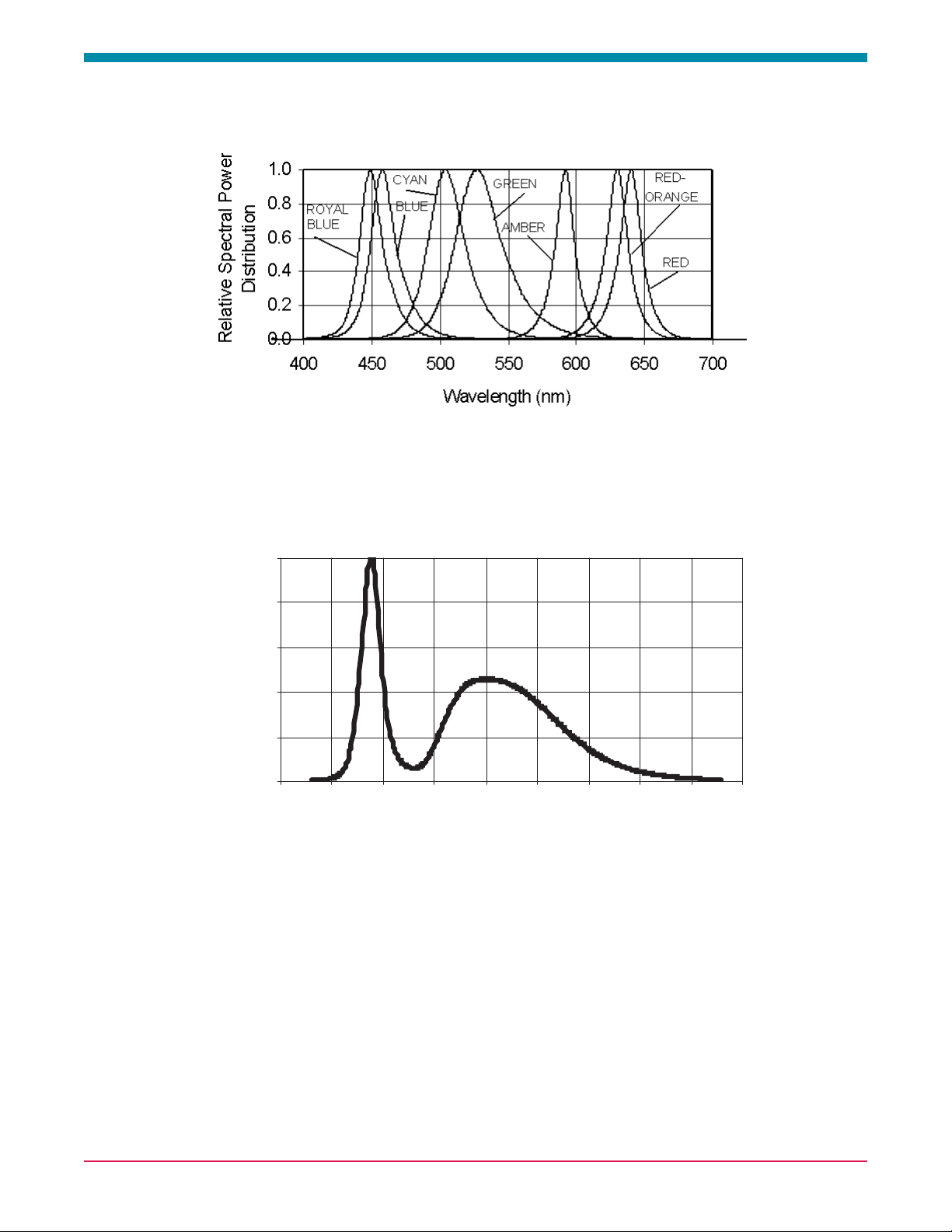
Wavelength Characteristics, TJ= 25ºC
Figure 1b. White Color Spectrum of Typical 5500K CCT Part, Integrated Measurement.
0.0
0.2
0.4
0.6
0.8
1. 0
350 400 450 500 550 600 650 700 750 800
Wavelength (nm)
Relative Specrtal Power
Distribution
Figure 1a. Relative Intensity vs. Wavelength
Page 10
Luxeon III Emitter DS45 (3/05)
10
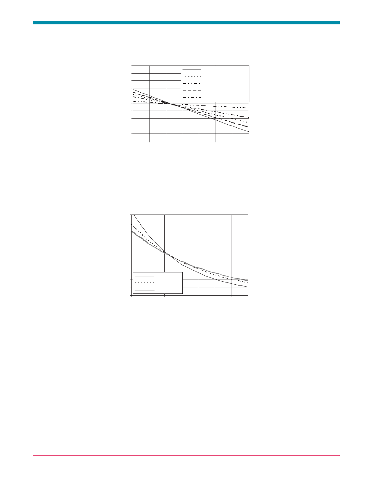
Light Output Characteristics
50
60
70
80
90
100
110
120
130
140
150
-20 0 20 40 60 80 100 120
Junction Temperature, TJ (oC)
Relative Light Output (%)
Green P ho to m etr ic
Cyan Photometric
Blue P hotometric
White Photometric
Royal Blue Radiometric
Figure 2. Relative Light Output vs. Junction Temperature
for White, Green, Cyan, Blue and Royal Blue.
Figure 3. Relative Light Output vs. Junction Temperature
or Red, RedOrange and Amber.
0
20
40
60
80
100
120
140
160
180
200
-20 0 20 40 60 80 100 120
Junction Temperatur e, TJ (oC)
Relative Li ght Output (%)
Red
Red-Orange
Amber
Page 11

Luxeon III Emitter DS45 (3/05)
11
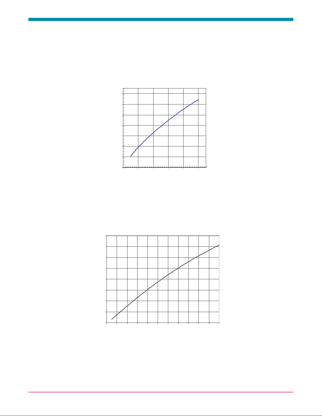
Forward Current Characteristics, TJ= 25ºC
Note:
Driving these high power devices at currents less than the test conditions may produce unpredictable results and may be subject
to variation in performance. Pulse width modulation (PWM) is recommended for dimming effects.
0
200
400
600
800
1000
1200
1400
1600
1800
2000
2200
1.00 1.25 1.50 1.75 2.00 2.25 2.50 2.75 3.00 3.25 3.50 3.75 4.00
Vf - Forw ard Voltage (V olts)
Average Forward Current (mA
Figure 5. Forward Current vs. Forward Voltage for Red,
RedOrange and Amber.
0
100
200
300
400
500
600
700
800
900
1000
1100
0 1 2 3 4
5
Vf - Forward Voltage (Volts)
Average Forward Current (mA)
Figure 4. Forward Current vs. Forward Voltage for White,
Green, Cyan, Blue, and Royal Blue.
Page 12
Luxeon III Emitter DS45 (3/05)
12
Forward Current Characteristics, TJ= 25ºC, Continued
Note:
Driving these high power devices at currents less than the test conditions may produce unpredictable results and may be subject
to variation in performance. Pulse width modulation (PWM) is recommended for dimming effects.
0.0
0.2
0.4
0.6
0.8
1.0
1.2
1.4
1.6
0 200 400 600 800 1000 1200 1400 1600 1800 2000 2200
If - Forward Current (mA)
Normaliz ed Relative Luminous Flux
Figure 7. Relative Luminous Flux vs. Forward Current for Red,
RedOrange and Amber at T
J
= 25ºC maintained.
0.0
0.2
0.4
0.6
0.8
1.0
1.2
1.4
0 200 400 600 800 1000
If - Forward Current (mA)
Normalized Luminous Flux
Figure 6. Relative Luminous Flux vs. Forward Current for White,
Green, Cyan, Blue, and Royal Blue at T
J
= 25ºC maintained.
Page 13
Luxeon III Emitter DS45 (3/05)
13
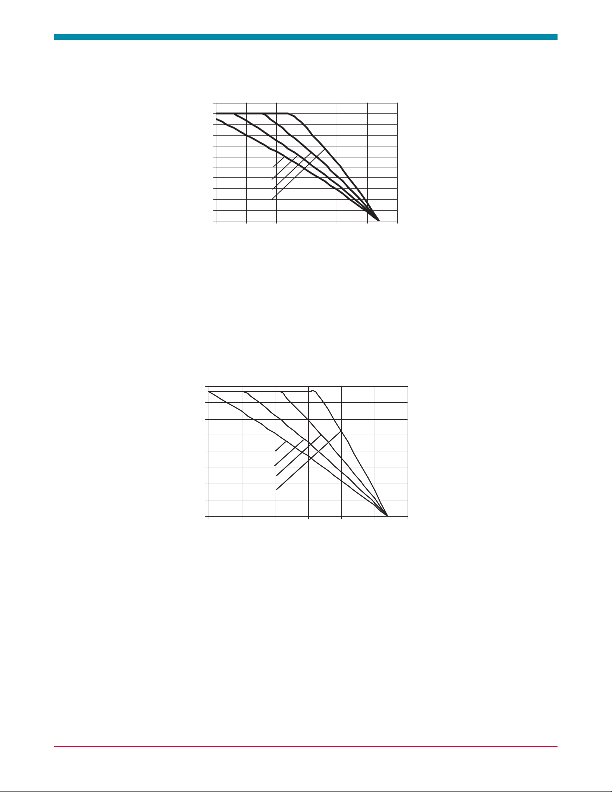
Current Derating Curves
0
100
200
300
400
500
600
700
800
900
1000
1100
0 25 50 75 100 125 150
TA - Ambient Temperature (οοC)
I
F
- Forward Current (mA)
Rθ
J-A
=30oC/W
Rθ
J-A
=25oC/W
Rθ
J-A
=20oC/W
Rθ
J-A
=15oC/W
0
200
400
600
800
1000
1200
1400
1600
0 25 50 75 100 125 150
TA - A mbient Temperature (oC)
I
F
- Forward Current (mA)
R
θ
J-A
=25oC/W
R
θ
J-A
=20oC/W
R
θ
J-A
=15oC/W
R
θ
J-A
=10oC/W
Figure 8. Maximum Forward Current vs. Ambient Temperature.
Derating based on T
JMAX
= 135°C for White, Green, Cyan, Blue, and Royal Blue. Since Luxeon III may be driven at up to 1000mA,
derating curves may not be applicable for all operating conditions.
Figure 9. Maximum Forward Current vs. Ambient Temperature
derating based on T
JMAX
= 135°C for Red, RedOrange, and Amber.
Page 14
Luxeon III Emitter DS45 (3/05)
14
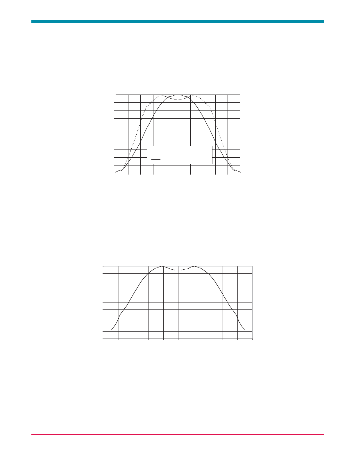
Typical Lambertian Representative Spatial Radiation Pattern
Note:
For more detailed technical information regarding Luxeon radiation patterns, please consult your Lumileds Authorized Distributor
or Lumileds sales representative.
0
10
20
30
40
50
60
70
80
90
100
-100-80-60-40-200 20406080100
Angular Displacment (Degrees)
Relative Intensity (%)
Typical Upper Bound
Typical Lower Bound
Figure 10. Typical Representative Spatial Radiation Pattern
for Luxeon Emitter White, Green, Cyan, Blue and Royal Blue.
Figure 11. Typical Representative Spatial Radiation Pattern
for Luxeon Lambertian Emitter Red, RedOrange and Amber.
0%
10%
20%
30%
40%
50%
60%
70%
80%
90%
100%
-100 -80 -60 -40 -20 0 20 40 60 80 100
Angular Displacement (Degrees)
Relative Intensity
Page 15
Luxeon III Emitter DS45 (3/05)
15
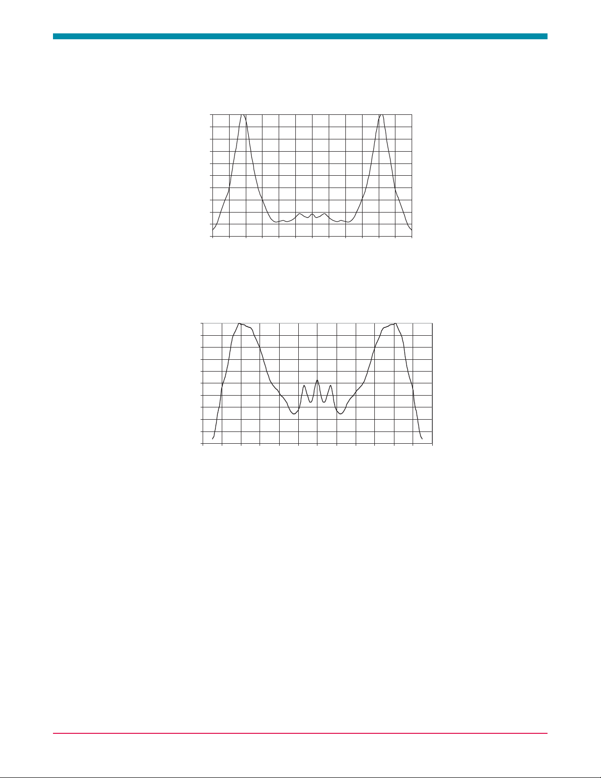
Typical Side Emitting Representative Spatial Radiation Pattern
Average Lumen Maintenance Characteristics
Lifetime for solidstate lighting devices (LEDs) is typically defined in terms of lumen maintenancethe percentage of
initial light output remaining after a specified period of time. Lumileds projects that white, green, cyan, blue, and royal blue
Luxeon III products will deliver, on average, 70% lumen maintenance at 50,000 hours of operation at a 700 mA forward current
or 50% lumen maintenance at 20,000 hours of operation at a 1000 mA forward current. Lumileds projects that red, redorange,
and amber Luxeon III products will deliver, on average 50% lumen maintenance at 20,000 hours of operation at a 1400 mA
forward current. This performance is based on independent test data, Lumileds historical data from tests run on similar material
systems, and internal Luxeon reliability testing. This projection is based on constant current operation with junction temperature
maintained at or below 90°C. Observation of design limits included in this data sheet is required in order to achieve this
projected lumen maintenance.
Figure 12. Typical Representative Spatial Radiation Pattern
for Luxeon Emitter White, Green and Blue.
Figure 13. Typical Representative Spatial Radiation Pattern
for Luxeon Emitter Red, RedOrange and Amber.
0
10
20
30
40
50
60
70
80
90
100
-120 -100 -80 -60 -40 -20 0 20 40 60 80 100 120
Angular Displacement (Degrees)
Relative Intensity (%)
Side Emitting Radiation Pattern
0%
10%
20%
30%
40%
50%
60%
70%
80%
90%
100%
-120 -100 -80 -60 -40 -20 0 20 40 60 80 100 120
Angular Displacement (Degrees)
Relative Intensity
Page 16

Luxeon III Emitter DS45 (3/05)
16
Emitter Reel Packaging
Notes:
1.Luxeon emitters should be picked up by the body (not the lens) during placement. The inner diameter of the pickup collet
should be greater than or equal to 6.5 mm. Please consult Lumileds' Application Brief AB10 on Luxeon Emitter assembly
information for further details on assembly methods.
2.Drawings not to scale.
3.All dimensions are in millimeters.
4.All dimensions without tolerances are for reference only.
Figure 14. Reel dimensions and orientation.
Lambertian
Side Emitting
Figure 15. Tape dimensions for Lambertian and
Side Emitting radiation pattern.
 Loading...