

Page 1
2kb SPI EEPROM with PIO, RTC,
DS28DG02
Reset, Battery Monitor, and Watchdog
www.maxim-ic.com
GENERAL DESCRIPTION
The DS28DG02 combines 2kb (256 x 8) EEPROM
with 12 PIO lines, a real-time clock (RTC) and
calendar with alarm function, a CPU reset monitor, a
battery monitor, and a watchdog. Communication
with the device is accomplished with an industrystandard SPI™ interface. The user EEPROM is
organized as four blocks of 64 bytes each with
single-byte and up to 16-byte page write capability.
Additional registers provide access to PIOs and to
setup functions. Individual PIO lines can be
configured as inputs or outputs. The power-on state
of PIOs programmed as outputs is stored in
nonvolatile (NV) memory. All PIOs may be
reconfigured by the user through the serial interface.
The RTC/calendar operates in the 12/24-hour format
and automatically corrects for leap years. Battery
monitor threshold and watchdog timeout are userprogrammable through NV registers. The reset
monitor generates a reset to the CPU if the voltage at
the V
output includes a debounce circuit for manual
pushbutton reset.
pin falls below the factory-set limit. The reset
CC
APPLICATIONS
Asset-Tracking Systems
Broadband Access Network Equipment
Patient-Monitoring Systems
Home Lighting Control Systems
Holter Heart Monitors
Typical Operating Circuit appears on page 32.
Pin Configuration appears on page 33.
ORDERING INFORMATION
PART TEMP RANGE VCC TRIP PIN-PACKAGE PKG CODE
DS28DG02E-3C+ -40°C to +85°C 3.3V -5% 28 TSSOP-EP* (4.4mm) U28E+5
DS28DG02E-3C+T -40°C to +85°C 3.3V -5% 28 TSSOP-EP* T&R U28E+5
DS28DG02G-3C+ -40°C to +85°C 3.3V -5% 36 TQFN-EP* (6mm × 6mm) T3666+3
DS28DG02G-3C+T -40°C to +85°C 3.3V -5% 36 TQFN-EP* T&R T3666+3
*EP = Exposed Paddle.
+ Denotes lead-free/RoHS compliant device.
For additional VCC monitor trip points or other device options, contact the factory.
Note: Registers are capitalized for clarity.
SPI is a trademark of Motorola, Inc.
FEATURES
2kb (256 x 8) EEPROM Organized in Four
64-Byte Blocks
Single Byte and Up to 16-Byte EEPROM Write
Sequences
EEPROM Write-Protect Control Pin Protects
1, 2, or All 4 Blocks
Endurance 200k Cycles per Page at +25°C;
10ms (max) EEPROM Write Cycle
SPI Serial Interface Supporting Modes (0,0)
and (1,1) at Up to 2MHz Clock Frequency
12 PIO Lines with LED Drive Capability
Each PIO is Configured to Input or Output,
Open-Drain/Push-Pull on Startup by Stored
Value
All PIOs are Reconfigurable After Startup
RTC/Calendar/Alarm with BCD Format and
Leap-Year Compensation
RTC Controlled Through 32.768kHz, 12.5pF
Crystal or External TCXO
CPU Reset Through Fast-Response Precision
Monitor with Hysteresis or Pushbutton
V
CC
Battery Monitor 2.5V, 2.25V, 2.0V, 1.75V, -5%
Watchdog Timer 1.6s, 0.8s, 0.4s, 0.2s (typ)
Unique Factory-Programmed 64-Bit Device
Registration Number
Operating Range: 2.2V to 5.25V,
-40°C to +85°C
±4kV IEC 1000-4-2 ESD Protection Level
(Except Crystal Pins)
Available in 28-Lead, 4.4mm TSSOP or
36-Lead 6mm × 6mm QFN Package
Note: Some revisions of this device may incorporate deviations from published specifications known as errata. Multiple revisions of any device
may be simultaneously available through various sales channels. For information about device errata, click here: www.maxim-ic.com/errata
1 of 33
REV: 061907
.
Page 2

DS28DG02: 2kb SPI EEPROM with PIO, RTC, Reset, Battery Monitor, and Watchdog
ABSOLUTE MAXIMUM RATINGS
Voltage Range on Any Pin Relative to Ground -0.5V, +6V
Maximum Current SO, ALMZ, RSTZ, WDOZ Pins
Maximum Current Each PIO Pin
Maximum GND and V
Current 270mA
CC
Operating Temperature Range
Junction Temperature
+150°C
Storage Temperature Range
Soldering Temperature
See IPC/JEDEC J-STD-020
-40°C to +85°C
-55°C to +125°C
±20mA
±50mA
Stresses beyond those listed under “Absolute Maximum Ratings” may cause permanent damage to the device. These are stress ratings only,
and functional operation of the device at these or any other conditions beyond those indicated in the operational sections of the specifications is
not implied. Exposure to the absolute maximum rating conditions for extended periods may affect device.
ELECTRICAL CHARACTERISTICS
(TA = -40°C to +85°C.)
PARAMETER SYMBOL CONDITIONS MIN TYP MAX UNITS
Supply Voltage VCC
Battery Voltage V
Battery Current (V
= 3.0V,
BAT
Note 1)
Standby Current (Note 2) I
Operating Current I
Programming Current I
VCC Monitor Trip Point V
VCC Monitor Trip-Point
Tolerance
VCC Monitor Hysteresis V
Power-Up Wait Time t
I
BAT
CCS
CCA
PROG
V
TRIPTOL
HYST
POIP
BAT
TRIP
EEPROM
Programming Time t
Endurance N
Data Retention t
PROG
CYCLE
RET
REAL-TIME CLOCK
Frequency Deviation
Δ
F
PIO PINS (See Figures 21, 22, 23)
LOW-Level Output Current at
= 0.5V (Note 8)
V
OL
(Note 8)
I
OL
I
OH
Battery monitor off 2.2 5.25
Battery monitor enabled 2.7 5.25
V
(Note 1) 1.5 3.0 VCC V
RTC oscillator off 2
RTC oscillator on 0.4 10
µA
RTC oscillator on, +25°C 4.7
SPI idle, ALMZ, WDOZ,
RTSZ high, V
RTC oscillator on, all
= 5.25V,
CC
60 100 µA
PIOs grounded
Reading EEPROM at 2
Mbps, ALMZ, WDOZ,
RTSZ high, V
= 5.25V,
CC
550 800 µA
RTC oscillator on, all
PIOs grounded
VCC = 5.25V 600 1000 µA
(Note 3) 2.97 3.05 3.14 V
+25°C
-40°C to +85°C -2.5 +2.5
0.4 0.5 0.6 %V
-1.5 +1.5
%V
TRIP
TRIP
60 µs
10 ms
At +25°C (Notes 4, 5) 200k —
At +85°C (Notes 5, 6) 40 years
(Notes 5, 7) -46 +46 PPM
VCC = 2.2V 6 9.5
VCC = 3.3V 12.5 22.0
= 5.25V 19 30
V
CC
VOH = 2.4V, VCC = 3.3V 6.5 11.0 HIGH-Level Output Current
= 4.5V, VCC = 5.25V 12.5 18.0
V
OH
mA
mA
2 of 33
Page 3

DS28DG02: 2kb SPI EEPROM with PIO, RTC, Reset, Battery Monitor, and Watchdog
PARAMETER SYMBOL CONDITIONS MIN TYP MAX UNITS
LOW-Level Input Voltage VIL 0.8 V
HIGH-Level Input Voltage VIH
Output Transition Time tOT
Power-On Setting Time
t
POS
Low-current mode
(Note 9)
High-current mode
(Note 10)
High-current mode
(Note 11)
0.7 ×
V
CC
1
25
25 µs
V
CC
0.5V
+
V
µs
PIO Read Setup Time tPS (Note 5) 100 ns
PIO Read Hold Time tPH (Note 5) 100 ns
Leakage Current IL
High impedance, at
CCMAX
V
-1 +1 µA
RSTZ PIN (Note 12) (See Figures 6, 7)
LOW-Level Output Voltage VOL At 4mA sink current 0.3 V
LOW-Level Input Voltage VIL
0.3 ×
V
CC
V
Input Leakage Current IL -1 +1 µA
Minimum VCC for Valid RSTZ V
RSTZ Pulse Duration t
Manual Reset Pulse Width t
Manual Reset Release
Threshold
Manual Reset Debounce Time t
RSTZ Delay t
(Notes 5, 13) 2.13 V
POR
176 328 532 ms
RST
1 µs
MPW
V
(Note 14) VIL V
TRMS
t
DEB
V
DEL
falling below V
CC
(Note 15)
TRIP
90 µs
ms
RST
ALMZ, WDOZ PINS
LOW-Level Output Voltage VOL At 4mA sink current 0.3 V
WDI PIN
LOW-Level Input Voltage VIL
HIGH-Level Input Voltage VIH
0.7 ×
V
CC
0.3 ×
V
CC
VCC +
0.5V
V
V
Input Leakage Current IL -1 +1 µA
Minimum Input Pulse Width t
Watchdog Timeout tWD User programmable
1 µs
MPW
0.88
0.44
0.22
0.11
1.64
0.82
0.41
0.20
2.66
1.33
0.67
0.33
s
WPZ, SI, SCK, CSZ PINS
LOW-Level Input Voltage VIL
HIGH-Level Input Voltage VIH
0.7 ×
V
CC
0.3 ×
V
CC
V
+
CC
0.5V
V
V
Input Leakage Current IL -1 +1 µA
SO PIN
LOW-Level Output Voltage VOL
HIGH-Level Output Voltage VOH At 1mA source current
Output Leakage Current IL
At 1mA sink current and
V
CCmin
High impedance, at
V
CCmax
0.2 V
0.7 ×
V
CC
V
-1 +1 µA
3 of 33
Page 4

DS28DG02: 2kb SPI EEPROM with PIO, RTC, Reset, Battery Monitor, and Watchdog
PARAMETER SYMBOL CONDITIONS MIN TYP MAX UNITS
BATTERY MONITOR (See Figure 8)
V
Trip Point V
BAT
Monitor Trip-Point
BAT
Tolerance
V
Battery Test Load Current I
Battery Test Duration t
2.25
2.03
1.80
1.58
2 s
BTP
Measured with V
falling; trip point is user
BAT
programmable
+25°C -1.5 +1.5 V
TRIPTOL
LOAD
BTPW
-40°C to +85°C -2.5 +2.5
7.5 20 µA
Load applied to battery
(Notes 5, 16)
2.31
2.08
1.85
1.62
2.38
2.14
1.90
1.66
%V
V
BTP
SPI INTERFACE TIMING (See Figures 9, 10)
CSZ Setup Time t
CSZ Hold Time t
(Note 5)
CSZ to High-Z at SO t
SCK Clock Frequency f
(Note 5) 0.4 µs
CSS
(Note 5) 0.4 µs
CSH
t
CPH
CHZ
CLK
Normal communication 0.25 CSZ Standby Pulse Width
(Note 17) 2.0
µs
0.25 µs
2 MHz
Data Setup Time tDS (Note 5) 50 ns
Data Hold Time tDH (Note 5) 50 ns
SCK Rise Time t
SCK Fall Time t
(Note 5) 1 µs
SCKR
(Note 5) 1 µs
SCKF
Output Valid time tV (Note 5) 0 120 ns
Note 1:
Note 2:
Note 3:
Note 4:
Note 5:
Note 6:
Note 7:
Note 8:
Note 9:
Note 10:
Note 11:
Note 12:
Note 13:
Note 14:
Note 15:
Note 16:
Note 17:
If no battery is used, connect the V
To the first order, this current is independent of the supply voltage value.
Nominal values: 3.3V -5%, set at factory. Measured with V
V
TRIP
+ V
HYST
.
This specification is valid for each 16-byte memory page.
Not production tested. Either guaranteed by design (GBD) or guaranteed by a reliability study (EEPROM lifetime
parameters).
EEPROM writes can become nonfunctional after the data-retention time is exceeded. Long-time storage at
elevated temperatures is not recommended; the device can lose its write capability after 10 years at +125°C or 40
years at +85°C.
Valid with 32KHz crystal, 12.5pF, ESR ≤ 45kΩ, +25°C.
Total PIO sink and source currents through all PIO pins must be externally limited to less than the absolute
maximum rating of 270mA minus 1.5mA for EEPROM programming and SPI communication. Exceeding the
absolute maximum rating can cause damage.
Assumes the configuration of the system and the part is such that changing GOV<i> (0 ≤ i ≤ 11) between ‘b1 and
‘b0 switches between sourcing no current and sinking the absolute maximum current at the PIO<i> pin. The limit
refers to the switching time between sinking 20% of the DC current and 80% of the DC current. The same is true
for changing between 'b0 and 'b1 causing the part to switch from sinking no current to sourcing the absolute
maximum current at the PIO<i> pin.
Each output pin transitions in 1µs with a pause of 1µs before the next pin transitions.
All PIO are tri-stated at beginning of reset prior to setting to power-on values.
If the part has battery power (normal case) the active pulldown of RSTZ is supported by the battery.
is tied to VCC (no battery supply) the state of the RSTZ pulldown transistor is not guaranteed when VCC falls
If V
BAT
below V
POR
.
Threshold refers to the manual reset function obtained by forcing RSTZ low.
Transient response to a step on V
are guaranteed to be suppressed, regardless of their amplitude. Glitches on VCC that are longer than t
t
DELmin
are guaranteed not to be suppressed. This parameter is tested at high V
If enabled, this test takes place every hour on the hour. The battery voltage is compared to V
half of the t
window. The timing is controlled by the RTC.
BTPW
Extended duration applies to the following cases:
1) Aborted WREN, WRDI, RDSR, and WRSR command.
2) WRITE command aborted before transmitting the first complete data byte after command and address.
3) READ command aborted before reading the first complete data byte after command and address.
4) Read aborted before the end of a byte.
pin to VCC. The RTC is powered by V
BAT
falling; for VCC rising, the actual threshold is
CC
from above V
CC
down to (V
TRIP
TRIP
if VCC falls below V
BAT
CCmin
.
- 1mV). Glitches on VCC that are shorter than
and guaranteed by design at low.
CC
during the second
BTP
DELmax
4 of 33
Page 5

DS28DG02: 2kb SPI EEPROM with PIO, RTC, Reset, Battery Monitor, and Watchdog
PIN DESCRIPTION
NAME
TSSOP28 TQFN36
X1 1 33
X2 2 34
RSTZ 3 36
WDI 4 2
WDOZ 5 3
WPZ 6 4
PIO0 7 5
PIO4 8 6
PIO8 9 7
GND 10, 19 9, 19
PIO10 11 10
PIO6 12 11
PIO2 13 12
VCC 14, 15 13, 15
PIO3 16 16
PIO7 17 17
PIO11 18 18
PIO9 20 21
PIO5 21 22
PIO1 22 23
ALMZ 23 24
SO 24 25
SI 25 26
SCK 26 28
CSZ 27 30
V
28 31 Backup Battery Supply for RTC and RSTZ support.
BAT
N.C. —
GND EP EP
PIN
1, 8, 14,
20, 27,
29, 32, 35
FUNCTION
32.768kHz Crystal Connection 1 or 32.768kHz Input from TCXO
32.768kHz Crystal Connection 2
Open-Drain Output Pin (Active Low) for V
power-fail reset,
CC
watchdog alarm, and Manual Reset Input. See Multifunction
Control/Setup Register description for more information.
Watchdog Input Pin (Active High). See Multifunction Control/Setup
Register description at address 134h for more information.
Open-Drain Output Pin (Active Low) for (user-choice) watchdog
alarm. See Multifunction Control/Setup Register description for more
information.
Hardware Write-Protect Input Pin (Active Low). See the SPI Interface
description for more information.
PIO Line #0
PIO Line #4
PIO Line #8
Ground Supply
PIO Line #10
PIO Line #6
PIO Line #2
Power Supply Input
PIO Line #3
PIO Line #7
PIO Line #11
PIO Line #9
PIO Line #5
PIO Line #1
Open-Drain Output Pin (Active Low) for RTC, battery monitor, and
(user-choice) watchdog alarms. See the Multifunction Control/Setup
Register description for more information.
SPI Serial Data Output (tristate)
SPI Serial Data Input
SPI Serial Clock Input
Chip Select Input (Active Low)
No Connection
Exposed Paddle. Solder evenly to the board’s ground plane for proper
operation. See
Application Note 3273 for additional information.
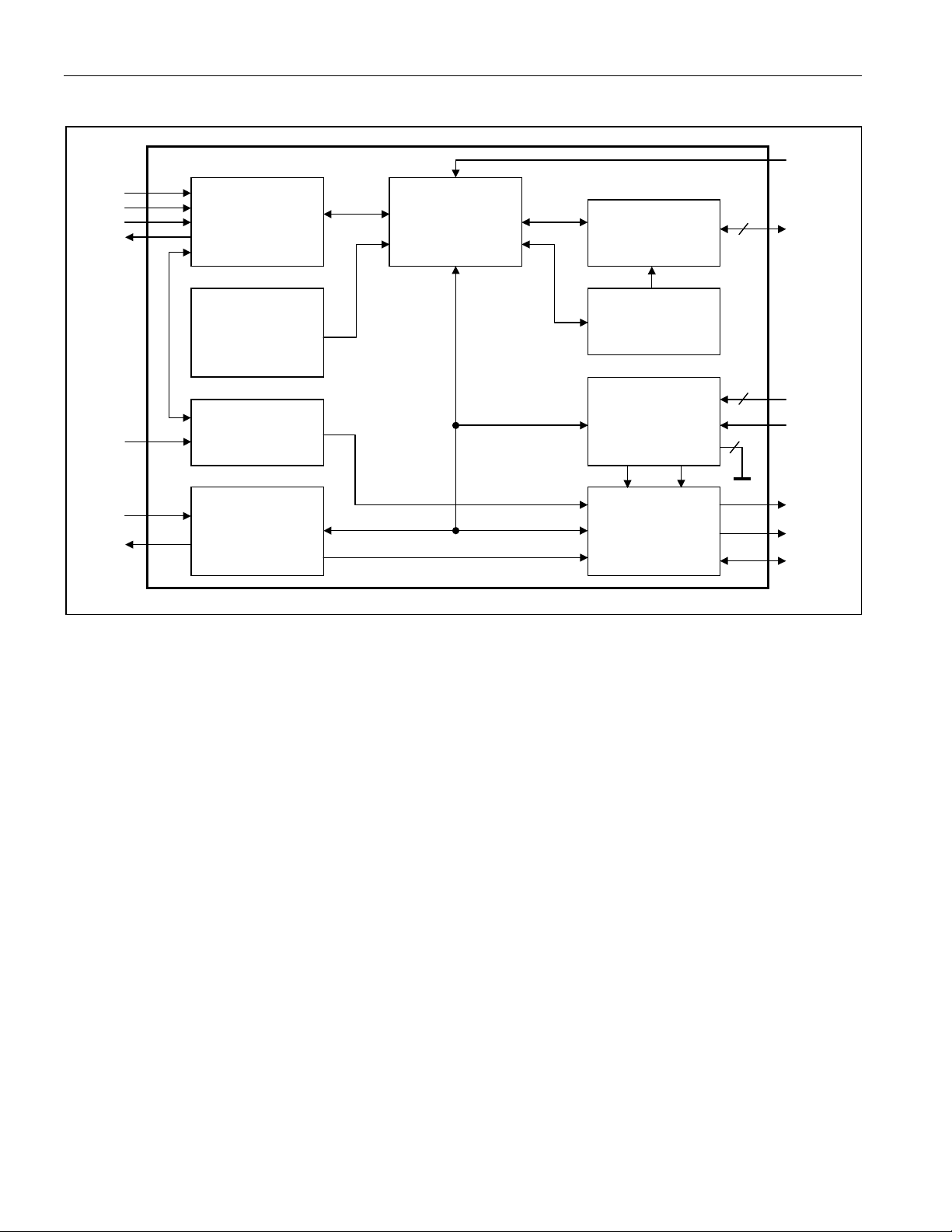
OVERVIEW
The DS28DG02 features 2kb of EEPROM, 12 bidirectional PIO channels, an RTC with calendar and alarm
function, a watchdog timer, two voltage monitors with precision trip points, and three alarm/reset outputs. Each
DS28DG02 has its own unique registration number, which serves as identification of the product the device is
embedded in. All these resources are accessed through a serial SPI interface, as shown in the block diagram in
Figure 1. The SPI interface automatically adjusts to SPI modes (0,0) and (1,1). The V
the power-fail reset output (RSTZ pin), is set at the factory. The user can set the battery monitor threshold and the
watchdog time-out through software. The RTC uses the common BCD format for time, calendar and day of the
week. The device can be programmed to generate an RTC alarm every second, minute, hour, or day and once a
week or once a month at a user-defined time. RTC, watchdog, and battery alarm can be individually enabled.
trip point, which controls
CC
5 of 33
Page 6
DS28DG02: 2kb SPI EEPROM with PIO, RTC, Reset, Battery Monitor, and Watchdog
K
A
Figure 1. Block Diagram
WPZ
CSZ
SC
SI
SO
SPI
Communication
Interface
64-bit Unique
Registration
Memory
Function Buffer
and Control
PIO Function
Control
2kb
EEPROM Array
12
PIOn
Number
WDI
X1
X2
Watchdog
Timer
Real-Time
Clock, Calendar
and RTC Alarm
WDA
CLKA
2
Voltage Monitors
and Power
Distribution
BATA VCLA
2
Alarm Control
Logic, RSTZ
Debounce
V
CC
V
BAT
GND
LMZ
WDOZ
RSTZ
The PIO configuration and setup of RTC/calendar with alarm are part of the Detailed Register Description. This
section also includes specifics of the Multifunction Control/Setup register, which enables/disables several device
functions, and the Alarm/Status register. For detailed information on the operation of the V
monitor/power-fail
CC
reset and the battery monitor see the Monitoring Functions section. The SPI Interface description explains the
communication protocol for memory and register access and the use of the watchdog function. The PIO
Read/Write Access section illustrates the behavior of the PIOs, in particular the address generation and timing in
low- and high-current mode.
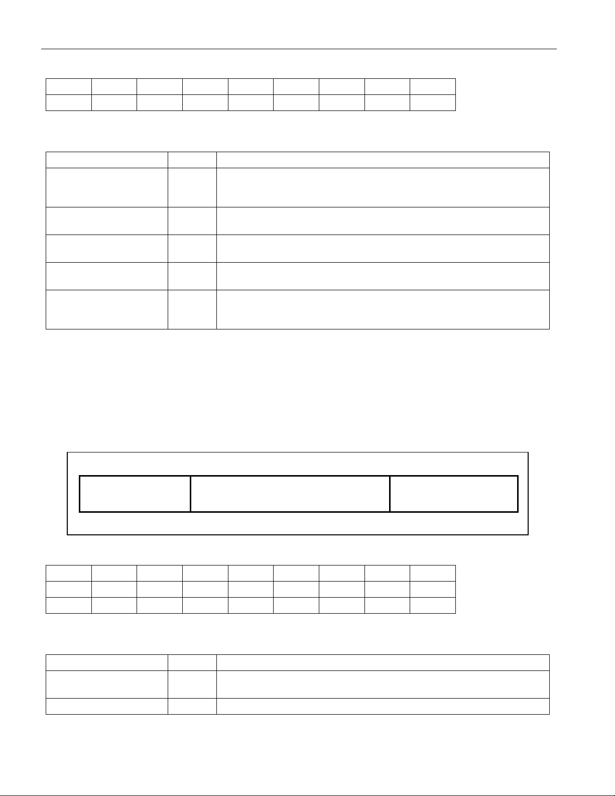
The DS28DG02 memory map (Figure 2) begins with 256 bytes of general-purpose user EEPROM, organized as
four blocks of 64 bytes. Additional EEPROM is set aside to store power-on defaults for PIO state (high, low, in
output mode), data direction (in, out), read-inversion (true, false), port output type (push-pull, open-drain), and
output mode (high current, low current). Once powered up, the PIO settings can be overwritten through SRAM
registers without affecting the power-on defaults. PIO state, direction, and read-inversion can be set for individual
ports. The output type is set for groups of four PIOs and the selected output mode applies to all PIOs in output
mode. The RTC/calendar, associated Alarm registers and the Multifunction Control/Status registers are kept
nonvolatile through battery backup. Write-protection, if enabled, is available for all four EEPROM blocks, blocks 2
and 3 only, or block 3 only and for all writeable registers from address 120h and higher.
6 of 33
Page 7

DS28DG02: 2kb SPI EEPROM with PIO, RTC, Reset, Battery Monitor, and Watchdog
Figure 2. Memory Map
ADDRESS TYPE ACCESS DESCRIPTION
000h to 03Fh EEPROM R/W User memory block 0.
040h to 07Fh EEPROM R/W User memory block 1.
080h to 0BFh EEPROM R/W User memory block 2.
0C0h to 0FFh EEPROM R/W User memory block 3.
100h to 109h — — Reserved, contents undefined.
10Ah EEPROM R/W Power-on default for PIO output state (PIO0 to PIO7).
10Bh EEPROM R/W Power-on default for PIO output state (PIO8 to PIO11).
10Ch EEPROM R/W Power-on default for PIO direction (PIO0 to PIO7).
10Dh EEPROM R/W Power-on default for PIO direction (PIO8 to PIO11).
10Eh EEPROM R/W Power-on default for PIO read-inversion (PIO0 to PIO7).
Power-on default for PIO read-inversion (PIO8 to PIO11),
10Fh EEPROM R/W
110h to 117h — — Reserved, contents is undefined.
PIO output type (PIO0 to PIO11 in groups of 4 PIOs), PIO
output mode (same mode for all PIOs).
118h to 11Fh ROM R 64-bit unique registration number.
120h SRAM R/W PIO output state (PIO0 to PIO7).
121h SRAM R/W PIO output state (PIO8 to PIO11).
122h SRAM R/W PIO direction (PIO0 to PIO7).
123h SRAM R/W PIO direction (PIO8 to PIO11).
124h SRAM R/W PIO read-inversion (PIO0 to PIO7).
PIO read-inversion (PIO8 to PIO11), PIO output type (PIO0
125h SRAM R/W
126h — R PIO read access (PIO0 to PIO7).
127h — R PIO read access (PIO8 to PIO11).
128h — — Reserved, contents undefined.
129h to 12Fh NV SRAM R/W RTC and calendar.
130h to 133h NV SRAM R/W RTC alarm.
134h NV SRAM R/W Multifunction control/setup register.
135h NV SRAM R/Clear Alarm and status register.
136h and above — — Reserved, contents undefined.
to PIO11 in groups of 4 PIOs), PIO output mode (same
mode for all PIOs).
7 of 33
Page 8

DS28DG02: 2kb SPI EEPROM with PIO, RTC, Reset, Battery Monitor, and Watchdog
DETAILED REGISTER DESCRIPTIONS
Power-On Default for PIO Output State
ADDR b7 b6 b5 b4 b3 b2 b1 b0
10Ah
10Bh
There is general read and write access to these addresses. Factory default: 10Ah: FFh; 10Bh: 0Fh. The contents of
this register are automatically transferred to address 120h/121h when the device powers up.
BIT DESCRIPTION BIT(S) DEFINITION
POVn: PIO Power-On
Default State
X: (Not Assigned) — Reserved for future use.
Power-On Default for PIO Direction
ADDR b7 b6 b5 b4 b3 b2 b1 b0
10Ch
10Dh
POV7 POV6 POV5 POV4 POV3 POV2 POV1 POV0
X X X X POV11 POV10 POV9 POV8
—
POD7 POD6 POD5 POD4 POD3 POD2 POD1 POD0
X X X X POD11 POD10 POD9 POD8
Power-on default output state of PIO0 to PIO11. POV0 applies to PIO0,
etc.
There is general read and write access to these addresses. Factory default: 10Ch: FFh; 10Dh: 0Fh. The contents
of this register are automatically transferred to address 122h/123h when the device powers up.
BIT DESCRIPTION BIT(S) DEFINITION
PODn: PIO Power-On
Default Direction
X: (Not Assigned) — Reserved for future use.
Power-On Default for PIO Read Inversion (PIO0 to PIO7)
ADDR b7 b6 b5 b4 b3 b2 b1 b0
10Eh
There is general read and write access to this address. Factory default: 00h. The contents of this register are
automatically transferred to address 124h when the device powers up.
BIT DESCRIPTION BIT(S) DEFINITION
PIMn: PIO Power-On
Default Read-Inversion
PIM7 PIM6 PIM5 PIM4 PIM3 PIM2 PIM1 PIM0
—
—
Power-on default direction of PIO0 to PIO11. POD0 applies to PIO0, etc.
Legend: 0 Î output; 1 Î input
Power-on default state of the read-inversion bit of PIO0 to PIO7. PIM0
applies to PIO0, etc.
Legend: 0 Î no inversion; 1 Î inversion
8 of 33
Page 9
DS28DG02: 2kb SPI EEPROM with PIO, RTC, Reset, Battery Monitor, and Watchdog
Power-On Default for PIO Read Inversion (PIO8 to PIO11), PIO Output Type and Output Mode
ADDR b7 b6 b5 b4 b3 b2 b1 b0
10Fh
POTM POT3 POT2 POT1 PIM11 PIM10 PIM9 PIM8
There is general read and write access to this address. Factory default: 80h. The contents of this register are
automatically transferred to address 125h when the device powers up.
BIT DESCRIPTION BIT(S) DEFINITION
PIMn: PIO Power-On
Default Read-Inversion
POT1: Power-On
Default Output Type
POT2: Power-On
Default Output Type
POT3: Power-On
Default Output Type
POTM: Power-On
Default Output Mode
b0 to b3
b4
b5
b6
b7
Power-on default state of the read-inversion bit of PIO8 to PIO11. PIM8
applies to PIO8, etc.
Legend: 0 Î no inversion; 1 Î inversion
Power-on default output type of PIO0 to PIO3;
Legend: 0 Î push-pull; 1 Î open drain
Power-on default output type of PIO4 to PIO7;
Legend: 0 Î push-pull; 1 Î open drain
Power-on default output type of PIO8 to PIO11;
Legend: 0 Î push-pull; 1 Î open drain
Power-on default output mode of PIO0 to PIO11;
Legend: 0 Î low-current, simultaneous switching; 1 Î high-current,
sequential switching
Unique Registration Number (118h to 11Fh)
Each DS28DG02 has a unique registration number that is 64 bits long, as shown in Figure 3. The registration
number begins with the family code at address 118h followed by the 48-bit serial number (LS-byte at the lower
address) and ends at address 11Fh with the Cyclic Redundancy Check (CRC) of the first 56 bits. This CRC is
generated using the a polynomial X
8
+ X5 + X
4
+ 1. Additional information about CRCs is available in Application
Note 27.
Figure 3. 64-Bit Registration Number
MSB LSB
8-Bit CRC Code 48-Bit Serial Number
8-Bit Family Code (70h)
MSB LSB MSB LSB MSB LSB
PIO Output State
ADDR b7 b6 b5 b4 b3 b2 b1 b0
120h
121h
OV7 OV6 OV5 OV4 OV3 OV2 OV1 OV0
X X X X OV11 OV10 OV9 OV8
There is general read and write access to these addresses. These registers are automatically loaded with data
from address 10Ah/10Bh when the device powers up.
BIT DESCRIPTION BIT(S) DEFINITION
OVn: PIO Output State —
Output state of PIO0 to PIO11. OV0 applies to PIO0, etc.
Legend: 0 Î LOW; 1 Î HIGH if PIO direction is output
X: (Not Assigned) — Reserved for future use.
9 of 33
Page 10

DS28DG02: 2kb SPI EEPROM with PIO, RTC, Reset, Battery Monitor, and Watchdog
PIO Direction
ADDR b7 b6 b5 b4 b3 b2 b1 b0
122h
123h
DIR7 DIR6 DIR5 DIR4 DIR3 DIR2 DIR1 DIR0
X X X X DIR11 DIR10 DIR9 DIR8
There is general read and write access to these addresses. These registers are automatically loaded with data
from address 10Ch/10Dh when the device powers up.
BIT DESCRIPTION BIT(S) DEFINITION
DIRn: PIO Direction —
Direction of PIO0 to PIO11. DIR0 applies to PIO0, etc.
Legend: 0 Î output; 1 Î input
X: (Not Assigned) — Reserved for future use.
PIO Read Inversion (PIO0 to PIO7)
ADDR b7 b6 b5 b4 b3 b2 b1 b0
124h
IMSK7 IMSK6 IMSK5 IMSK4 IMSK3 IMSK2 IMSK1 IMSK0
There is general read and write access to this address. This register is automatically loaded with data from address
10Eh when the device powers up.
BIT DESCRIPTION BIT(S) DEFINITION
IMSKn: PIO ReadInversion
—
Read-inversion bit of PIO0 to PIO7. IMSK0 applies to PIO0, etc.
Legend: 0 Î no inversion; 1 Î inversion
PIO Read Inversion (PIO8 to PIO11), PIO Output Type and Output Mode
ADDR b7 b6 b5 b4 b3 b2 b1 b0
125h
OTM OT3 OT2 OT1
IMSK11 IMSK10
IMSK9 IMSK8
There is general read and write access to this address. This register is automatically loaded with data from address
10Fh when the device powers up.
BIT DESCRIPTION BIT(S) DEFINITION
IMSKn: PIO ReadInversion
b0 to b3
OT1: Output Type b4
OT2: Output Type b5
OT3: Output Type b6
Read-inversion bit of PIO8 to PIO11. PIM8 applies to PIO8, etc.
Legend: 0 Î no inversion; 1 Î inversion
Output type of PIO0 to PIO3;
Legend: 0 Î push-pull; 1 Î open drain
Output type of PIO4 to PIO7;
Legend: 0 Î push-pull; 1 Î open drain
Output type of PIO8 to PIO11;
Legend: 0 Î push-pull; 1 Î open drain
Output mode of PIO0 to PIO11;
OTM: Output Mode b7
Legend: 0 Î low-current, simultaneous switching; 1 Î high-current,
sequential switching
10 of 33
Page 11

DS28DG02: 2kb SPI EEPROM with PIO, RTC, Reset, Battery Monitor, and Watchdog
PIO Read Access
ADDR b7 b6 b5 b4 b3 b2 b1 b0
126h
127h
IV7 IV6 IV5 IV4 IV3 IV2 IV1 IV0
0 0 0 0 IV11 IV10 IV9 IV8
There is only read access to these addresses. Bits 4 to 7 of address 127h always read 0. Read access is functional
for all PIOs, regardless of their direction setting. Reported is the logic state of the pin, which may be different from
what the PIO output value register implies.
BIT DESCRIPTION BIT(S) DEFINITION
IVn: Input Value of PIOn —
Logic state read from PIO0 to PIO11 pins. IV0 applies to PIO0, etc.
Legend: IVn = PIOn XOR’ed with IMSKn
Figure 4 shows a simplified schematic of a PIO. The flip flops are accessed through the PIO Output State (OVn)
and Read Access (IVn) registers and memory addresses 122h to 125 (DIRn, IMSKn, OTn). They are initialized at
power-up or during Refresh (see the SPI Interface Description) according to the data stored at memory addresses
10Ah to 10Fh. When a PIO is configured as input, the PIO output is tri-stated (high impedance). When a PIO is
configured as output, the PIO input is the same as the output state XORed with the corresponding read inversion
bit. The differences of the PIO behavior in low current and high current mode are explained in the PIO Read/Write
Access section near the end of this document.
Figure 4. PIO Simplified Schematic
from SPI Interface
from SPI Interface
from SPI Interface
from SPI Interface
CLK
OTn
DIRn
OVn
IMSKn
OTn
D Q
CLK
DIRn
D Q
CLK
OVn
D Q
CLK
IMSKn
D Q
CLK
IVn
D Q
CLK
Vcc
PIOn Pin
to SPI Interface
11 of 33
Page 12

DS28DG02: 2kb SPI EEPROM with PIO, RTC, Reset, Battery Monitor, and Watchdog
RTC and Calendar Registers
ADDR b7 b6 b5 b4 b3 b2 b1 b0
129h
12Ah
12Bh
0 10 Seconds Single Seconds
0 10 Minutes Single Minutes
0 12/24
10hrs
10hrs Single Hours
A/P
12Ch
12Dh
12Eh
12Fh
0 0 0 0 0 Day of Week
0 0 10 Date Single Date
0 0 0 Single Months
10 Years Single Years
There is general read and write access to these addresses. Bits shown as 0 cannot be written to 1. The RTC and
calendar registers are reset to 00h when the battery voltage ramps up. Writes take effect immediately. To prevent
unexpected increments during write access, first update the seconds; this creates a 1s window to finish updating
the RTC/Calendar registers without any carryover from the Seconds register. Whenever the DS28DG02 receives a
SPI Read command, the RTC and Calendar registers are copied to a buffer. When during a read access the
address counter points to the RTC/Calendar registers, data from the buffer is transmitted. To obtain most accurate
RTC data, start reading at the Seconds register.
The number representation of the RTC/Calendar registers is BCD (binary-coded decimal). The RTC can run in the
12-hour AM/PM and the 24-hour mode. The “12/24” bit (bit 6 of address 12Bh) defines the mode. For 12-hour
AM/PM mode, set this bit to 1; bit 5 of address 12Bh then indicates AM (0b) or PM (1b). In the 24-hour mode, bit 5
and bit 4 together indicate the multiple of 10 hours. The Day of Week register counts from 1 to 7. The calendar
logic is designed to automatically compensate for leap years. For every year value that is either 00 or a multiple of
4 the device will add a 29th of February. This will work correctly up to (but not including) the year 2100.
RTC Alarm Registers
ADDR b7 b6 b5 b4 b3 b2 b1 b0
130h
131h
132h
AM1 10 Seconds Single Seconds
AM2 10 Minutes Single Minutes
AM3 12/24
10hrs
10hrs Single Hours
A/P
133h
AM4 DY/DT
0 0 0 Day of Week
10 Date Single Date
There is general read and write access to these addresses. Bits shown as 0 cannot be written to 1. The RTC Alarm
registers are reset to 00h when the battery voltage ramps up. To generate an alarm, there must be a match
between Alarm registers and RTC registers. Alarm register addresses 130h to 132h correspond to RTC register
addresses 129h to 12Bh; bits 6:0 participate in the comparison. The lower 6 bits of register address 133h
correspond to 12Ch if DY/DT is 1 and to 12Dh if DY/DT is 0; the upper 2 bits of this register do not participate in the
comparison. The control bits AM1, AM2, AM3, and AM4 determine the frequency of the alarm, as shown in Table
1. When the alarm occurs, the CLKA bit of the Alarm and Status register at address 135h changes to 1. The RTC
must be running for the device to generate RTC alarms (OSCE at address 134h = 1).
12 of 33
Page 13

DS28DG02: 2kb SPI EEPROM with PIO, RTC, Reset, Battery Monitor, and Watchdog
Table 1. Alarm Frequency Control
DY/DT AM4 AM3 AM2 AM1 ALARM OCCURRENCE
X X X X 1 Every second
X X X 1 0 Every minute, when the seconds match
X X 1 0 0 Every hour, when minutes and seconds match
X 1 0 0 0 Every day, when hours, minutes, and seconds match
1 0 0 0 0 Every week, when day, hours, minutes, and seconds match
0 0 0 0 0 Every month, when date, hours, minutes, and seconds match
Multifunction Control/Setup Register
ADDR b7 b6 b5 b4 b3 b2 b1 b0
134h
There is general read and write access to this address. Bit 7 always reads 0; it cannot be written to 1. This register
is reset to 00h when the battery voltage ramps up. See Figure 5 for the use of the CAE, WDE, WDOS, and BME
bits in the generation of the ALMZ, RSTZ, and WDOZ signals.
BIT DESCRIPTION BIT(S) DEFINITION
CAE: Clock Alarm
Enable
OSCE: RTC Oscillator
Enable
WDE: Watchdog Enable b2
WDOS: Watchdog
Output Selection
BTRP: Battery Monitor
Trip Point
BME: Battery Monitor
Enable
Alarm and Status Register
0 BME BTRP WDOS WDE OSCE CAE
b0
b1
Enable/disable control of the RTC/Calendar alarm.
Legend: 0 Î disabled (power-on default); 1 Î enabled
Run/halt control of the RTC’s 32KHz oscillator
Legend: 0 Î halted (power-on default); 1 Î running
Enable/disable control of the watchdog and its alarm.
Legend: 0 Î disabled (power-on default); 1 Î enabled
The watchdog timer is reset by changing WDE from 0 to 1, V
(Power-on reset) or applying a positive pulse at the WDI pin.
b3
Pin selection for watchdog alarm signaling.
Legend: 0 Î WDOZ pin (power-on default); 1 Î ALMZ pin
Selection of the nominal Battery Monitor Trip Point voltage.
b5:b4
Legend: 00b Î 1.75V (power-on default); 01b Î 2.00V;
10b Î 2.25V; 11b Î 2.50V
Enable/disable control of the Battery Monitor and its alarm.
Legend: 0 Î disabled (power-on default); 1 Î enabled
b6
The battery test takes place a) after BME changes to 1, b) after V
ramps up, c) every hour on the hour. The
RTC must be running (OSCE
= 1) for the battery monitor to function.
ramp up
CC
CC
ADDR b7 b6 b5 b4 b3 b2 b1 b0
135h
0 BATA WPZV POR BOR CLKA WDA RST
There is general read access to this address; writing clears all bits to 0. Bit 7 always reads 0. See Figure 5 for the
use of the CLKA, WDA, and BATA bits in the generation of the ALMZ, RSTZ, and WDOZ signals.
13 of 33
Page 14

DS28DG02: 2kb SPI EEPROM with PIO, RTC, Reset, Battery Monitor, and Watchdog
A
A
A
A
BIT DESCRIPTION BIT(S) DEFINITION
RSTZ pin activity indicator; set whenever there is a pulse at RSTZ;
RST: Reset Flag b0
cleared by writing to the Alarm and Status register.
ramp up: 1; V
V
CC
attach: 0
BAT
Watchdog Alarm indicator; set whenever the watchdog is enabled AND
WDA: Watchdog Alarm b1
the watchdog timer expires; cleared by writing to the Alarm and Status
register.
ramp up: 0; V
V
CC
attach: 0
BAT
RTC/Calendar Alarm indicator; set whenever the clock alarm is enabled
CLKA: Clock Alarm b2
BOR: Battery-On Reset
Flag
POR: Power-On Reset
Flag
WPZV: Hardware Write
Protect Value
b3
b4
b5
AND RTC and RTC Alarm register match; cleared by writing to the
Alarm and Status register.
ramp up: 0; V
V
CC
attach: 0
BAT
Battery attach indicator; set whenever the voltage at V
above V
ramp up: not affected; V
V
CC
; cleared by writing to the Alarm and Status register.
BATmin
attach: 1
BAT
Power-On Reset indicator; set whenever the voltage at V
above V
ramp up: 1; V
V
CC
; cleared by writing to the Alarm and Status register.
CCmin
attach: 0
BAT
WPZ pin state readout; reports the logic state at the WPZ pin;
ramp up: WPZ pin state; V
V
CC
BAT
Low Battery indicator; set whenever the battery alarm is enabled AND if,
BATA: Battery Alarm b6
during a battery test, V
by writing to the Alarm and Status register.
ramp up: battery test if BME = 1; V
V
CC
is below the selected V
BAT
Figure 5. ALMZ, WDOZ, and RSTZ Generation
attach: not affected.
trip point; cleared
BAT
attach: 0
BAT
ramps up
BAT
ramps up
CC
BME
BAT
CAE
ALMZ
CLK
WDOZ
WDE
WD
WDOS
RSTZ
VCL
Debounce
BME, CAE, WDE, WDOS are defined in the Control/Setup register.
BATA, CLKA, WDA are alarm signals readable through the Alarm/Status register.
VCLA is the alarm output of the V
monitor.
CC
14 of 33
Page 15

DS28DG02: 2kb SPI EEPROM with PIO, RTC, Reset, Battery Monitor, and Watchdog
*
A
*
y
MONITORING FUNCTIONS
The DS28DG02 has two voltage monitors: one for the VCC supply voltage and another one for the battery that
supplies the RTC and associated registers if V
is switched off. If VCC falls below the V
CC
monitor activates the open-drain RSTZ output, as shown in Figure 6. There is a delay of t
trip point and RSTZ going LOW. As long as V
logic level at RSTZ does not exceed V
values below V
V
CC
. When VCC ramps up, RSTZ remains at LOW until the V
POR
OLmax
is above V
CC
. Without battery support, the state of the RSTZ output is undefined for
crossed, the voltage at RSTZ rises until it reaches V
debounce circuit, which holds RSTZ low for t
RST
. After t
TRMS
RST
or the device has a functioning battery backup, the
POR
threshold is reached. As V
TRIP
, the manual reset release threshold. This activates the
is expired, the voltage at RSTZ ramps up to the value of
the applied pullup voltage.
Figure 6. RSTZ Power-Fail Reset
VCC
V
TRIP
V
POR
V
CC
t
t
RSTZ
DEL
RST
threshold the VCC
TRIP
between crossing the
DEL
TRIP
is
With the V
< V
V
CC
*
VCC or the applicable pullup voltage for the RSTZ pin.
pin tied to VCC, the RSTZ behavior for
BAT
is undefined.
POR
s V
is crossed, the voltage at
TRIP
RSTZ starts rising, which triggers
the manual switch debounce
circuit and activates RSTZ for t
RST
.
The RSTZ pin is internally connected to a debounce circuit, which allows using a manually operated switch to
generate a reset signal. Figure 7 illustrates the timing of the manual reset. As the switch closes, it forces the
voltage at RSTZ to fall below V
LOW by both, the manual switch and the debounce circuit. When the manual switch is opened or t
(whichever occurs later) the voltage at RSTZ rises until it reaches V
which holds RSTZ low for t
RST
time of a manually generated reset is t
, which triggers the debounce circuit. Now the voltage at RSTZ is held at logic
ILmax
. This again triggers the debounce circuit,
TRMS
is over,
DEB
, after which the voltage at RSTZ ramps up to the pullup voltage. The minimum LOW
+ t
RST
.
DEB
Figure 7. RSTZ Manual Switch Debounce
Open
Manual
Switch
closed
V
CC
RSTZ
V
TRMS
RSTZ held low by
DS28DG02
t
DEB
RSTZ held low
manual switch
b
t
RST
For t
*
to start, the voltage at RSTZ has to cross V
RST
TRMS
VCC or the applicable pullup voltage for the RSTZ pin.
after t
is expired.
DEB
15 of 33
Page 16

DS28DG02: 2kb SPI EEPROM with PIO, RTC, Reset, Battery Monitor, and Watchdog
V
In contrast to the V
monitor, the battery monitor is active only for two seconds per hour, and only if it is enabled
CC
through the BME bit in the Multifunction Control/Setup register. In addition to this, the DS28DG02 must have
sufficient V
power and the RTC must be running (OSCE = 1). The battery test takes place a) immediately after
CC
enabling the battery monitor, and, if the battery monitor is enabled, b) every hour on the full hour, and c)
immediately after V
ramps up above V
CC
. Figure 8 shows the details.
POR
The battery test procedure begins with the DS28DG02 internally connecting the test load to the V
battery is near the end of its lifetime, this extra load causes the battery voltage to fall below V
BTP
pin. If the
BAT
, the Battery Trip
Point. After the stabilization window is over, the actual comparison of the battery voltage to the battery trip point
takes place. If at the beginning of or during the battery test window the battery voltage falls below V
, the battery
BTP
alarm flag BATA in the Alarm and Status register is set, which in turn activates the ALMZ output. The BATA flag is
cleared by a) replacing the battery, or b) by writing to the Alarm and Status register. The BATA flag is not cleared if
a subsequent battery test, e.g., one hour later or after power-cycling the DS28DG02, determines that the battery
voltage is above V
. Note that replacing the battery resets the RTC and clears the Multifunction Control/Setup
BTP
register.
Battery monitoring is only useful when performed regularly. Equipment that is powered-down for excessively long
periods can completely drain its battery without receiving any advanced warning. To prevent such an occurrence,
equipment using the battery-monitoring feature should be switched on periodically, e.g., once a month, to perform a
battery test.
Figure 8. Battery Monitor Operation
V
BAT
V
BTP
0
Test
Load
On
off
Stabilization
Window
Battery Test
Window
1s 1s
BATA
ALMZ
16 of 33
Page 17

DS28DG02: 2kb SPI EEPROM with PIO, RTC, Reset, Battery Monitor, and Watchdog
SPI INTERFACE
The DS28DG02 is a slave device that communicates with its master, a microcontroller, through the serial SPI
interface. This interface uses the signals CSZ (chip select), SCK (bit transfer clock), SI (serial input), and SO (serial
output). Common to SPI devices is a WPZ input (write protect), which can protect the nonvolatile bits in the SPI
Status register from inadvertent changes.
Pin Description
Chip Select (CSZ)
A low level on the CSZ pin selects the device; a high level deselects the device. A low-to-high transition on CSZ
after a valid EEPROM write sequence initiates an internal programming cycle. A programming cycle already
initiated or in progress will be completed, regardless of the CSZ input signal. When the device is deselected, SO
goes to the high-impedance state, allowing multiple parts to share the same SPI bus. After powerup, a low level on
CSZ is required prior to any sequence being initiated. The CSZ pin must remain low while the DS28DG02 is
receiving or transmitting data.
Serial Clock (SCK)
The SCK is used to synchronize the communication between a master and the DS28DG02. Instructions,
addresses, or data present on the SI pin are latched on the rising edge of the clock input, while data on the SO pin
is updated after the falling edge of the clock input.
Serial Input (SI)
The SI pin is used to transfer data into the device. It receives instructions, addresses, and data. Data is latched on
the rising edge of the serial clock.
Serial Output (SO)
The SO pin is used to transfer data out of the DS28DG02. During a read cycle, data is shifted out on this pin after
the falling edge of the serial clock.
Write Protect (WPZ)
The WPZ pin, if enabled, prevents writes to the nonvolatile bits in the SPI Status register. As factory default, the
WPZ pin function is disabled. This allows the user to install the DS28DG02 in a system with WPZ pin grounded and
still being able to write to the Status register. For more details see Principles of Operation.
SPI Modes and Bit Timing
The SPI protocol defines communication in full bytes with the MS bit being transmitted first. Every SPI
communication sequence begins with at least one byte written to the slave device. The first byte that the slave
receives from the master is understood as an instruction. Depending on the instruction the slave may need more
bytes, e.g., address and data; for a read function, after having received the instruction and address, the slave starts
sending data to the master.
The SPI protocol knows four communication modes, which differ in the polarity and phase of the SCK signal. The
DS28DG02 supports modes (0,0) and mode (1,1). These modes have in common that data is clocked into the
slave on the rising edge and clocked out to the master on the falling edge of SCK. The master then clocks in the
data on the rising edge of SCK. The DS28DG02 detects the mode from the logic state of SCK when CSZ gets
active (high to low transition). Therefore, SCK must be stable for the duration of a setup and hold time around the
falling edge of CSZ. Figures 9 and 10 show the timing details.
The read timing of these graphics begins with the first bit that the DS28DG02 transmits to the master and ends
when the master ends the communication by deactivating CSZ (low to high transition). The dotted line indicates the
transition between read and write, with the last bit of the command or address being clocked in on the rising edge
and the first bit of read data appearing at SO after the falling edge of SCK.
17 of 33
Page 18

DS28DG02: 2kb SPI EEPROM with PIO, RTC, Reset, Battery Monitor, and Watchdog
Figure 9. SPI Timing, Mode (0,0)
CSZ
SCK
SI
Writing to the device
t
CSS
t
DStDH
Data Valid
t
CSH
t
CPH
SO
High Impedance High Impedance
Reading from the device
CSZ
t
CLL
t
SCK
SO
CLH
Data Valid
t
V
SI
Figure 10. SPI Timing, Mode (1,1)
CSZ
SCK
Writing to the device
t
CSS
t
CSH
t
HO
t
CHZ
t
CPH
t
CSH
Legend: t
SI
SO
CSZ
SCK
SO
SI
= 0.5 * (1/f
CLH
CLK
- t
t
DStDH
Data Valid
High Impedance High Impedance
Reading from the device
t
CLLtCLH
t
HO
Data Valid
t
V
-t
SCKR
SCKF
) t
= 0.5 * (1/f
CLL
CLK
- t
18 of 33
SCKR
-t
) tHO = t
SCKF
t
CSH
VMIN
t
CHZ
Page 19

DS28DG02: 2kb SPI EEPROM with PIO, RTC, Reset, Battery Monitor, and Watchdog
Principles of Operation
The first byte that the DS28DG02 receives from the master after a falling edge on CSZ is interpreted as an instruction. The DS28DG02 supports a set of seven instructions, which are summarized in Figure 11. The protocol uses
only a single address byte. The 9th address bit necessary to access addresses of 100h and higher is included in
the instruction code, marked as "X".
Figure 11. SPI Instruction Set
INSTRUCTION NAME
WREN
Write Enable
WRDI
Write Disable
WRSR
Write Status Register
RDSR
Read Status Register
INSTRUCTION
CODE
0000 0110b Tx Instruction Code
0000 0100b Tx Instruction Code
0000 0001b
0000 0101b
PROTOCOL PURPOSE
To set the WEN bit in the SPI Status
register. (Enable Writes to Memory)
To clear the WEN bit in the SPI Status
register. (Disable Writes to Memory)
Tx Instruction Code
Tx SPI Status Byte
Tx Instruction Code
Rx SPI Status Byte
To update the SPI Status register.
To read SPI Status register; to detect the
end of an EEPROM write cycle.
To update the SRAM registers at
RFSH
Refresh Registers
0000 0111b Tx Instruction Code
addresses 120h to 125h with their
power-on default values without powercycling.
WRITE
Write to Memory
READ
Read Memory
0000 X010b
0000 X011b
Tx Instruction Code
Tx Address Byte
Tx Data Byte(s)
Tx Instruction Code
Tx Address Byte
Rx Data Byte(s)
To write to the memory, register, PIOs,
RTC, depending on the specified
or the
address.
To read from the memory, register, PIOs,
RTC, depending on the specified
or the
address.
The first four instructions relate to the SPI Status register, which contains control bits and a status bit. The SPI
Status register is not memory-mapped and can only be updated through SPI instructions. It holds several bits that
control an elaborate scheme to prevent inadvertent changes of data stored in the device:
A write-enable bit WEN that needs to be set through a write-enable instruction WREN before a write instruction
is accepted. The WEN bit is automatically cleared after successful execution of a write instruction.
Hardware write-protection of b7:b2 (nonvolatile bits) of the SPI Status register through the write-protect enable
bit WPEN in conjunction with the logic state at the WPZ pin.
Write-Protect bits for memory blocks and the registers from address 120h and higher.
The combined effect of WEN, WPEN, and WPZ is summarized in Table 2. The full description of the SPI Status
register bit functions is found in Figure 12.
Table 2. Write Protection Summary
WEN
BIT
0 x x Write-protected (because WEN = 0). Write-protected (because WEN = 0).
1 0 x Writeable (because WPEN = 0).
1 1 0
1 1 1
WPEN
BIT
WPZ
PIN
SPI STATUS REGISTER MEMORY
Conditional write access:
Write-protected (because WPEN = 1
AND the WPZ pin is at logic 0).
Writable (because WPEN = 1 AND the
WPZ pin is at logic 1).
BP1:BP0 control protection of
addresses 00h to FFh.
RPROT controls protection of
addresses 120h and higher.
19 of 33
Page 20

DS28DG02: 2kb SPI EEPROM with PIO, RTC, Reset, Battery Monitor, and Watchdog
Figure 12. SPI Status Register
ADDR b7 b6 b5 b4 b3 b2 b1 b0
N/A
BIT DESCRIPTION BIT(S) DEFINITION
RDYZ: Ready (ReadOnly Bit)
WEN: Write Enabled
(Read-Only Bit)
BP1:BP0: Block Write
Protect
WD1:WD0: Watchdog
Timeout
RPROT: Register
Protection
WPEN: Hardware Write
Protect Enable
WPEN
RPROT
WD1 WD0 BP1 BP0 WEN RDYZ
b0
b1
b3:b2
b5:b4
B6
b7
Indicates whether an EEPROM write cycle is in progress.
Legend: 0 Î ready (normal state); 1 Î write cycle in progress
Indicates whether the device will accept a WRITE instruction; set
through the WREN instruction; cleared through the WRDI instruction or
completion of a valid WRITE or a valid WRSR instruction.
Legend: 0 Î write disabled (power-on default); 1 Î write enabled
These bits specify which of the four user memory blocks are writeprotected (independent of WPEN and WPZ).
Legend: 00b Î not protected (factory default)
01b Î block 3 (0C0h to 0FFh) protected
10b Î blocks 2 and 3 (080h to 0FFh) protected
11b Î blocks 0 to 3 (000h to 0FFh) protected
These bits specify the duration of the watchdog timeout if the watchdog
is enabled (WDE at address 134h = 1).
Legend: 00b Î 1.64s (factory default); 01b Î 820ms
10b Î 410ms; 11b Î 200ms
These are nominal values; for tolerances see Electrical Characteristics.
Specifies whether the writeable addresses in the range of 120h and
higher are write-protected (independent of WPEN and WPZ).
Legend: 0 Î not protected (factory default); 1 Î protected
Specifies whether b7:b2 of the SPI Status register (nonvolatile bits) are
writeable or whether the WPZ pin state controls the write-protection.
Legend: 0 Î writeable (factory default)
1 Î protection controlled by WPZ pin state
If WPEN = 1 and WPZ pin state is 0 the SPI Status register is writeprotected and a WRSR instruction is not valid.
DETAILED DESCRIPTION—SPI INSTRUCTION SET
WREN Write Enable
Before any write access to the device, the WEN bit in the SPI Status register must be set. The only way to set this
bit is through the write-enable instruction. The WEN bit is cleared when the device powers up, after the successful
execution of a write access instruction (WRSR or WRITE) and through WRDI. Figure 13 shows the instruction’s
timing diagram for both SPI communication modes.
WRDI Write Disable
The WRDI instruction can be used to clear the WEN bit of the SPI Status register, e.g., after an unsuccessful write
access instruction. Figure 14 shows the instruction’s timing diagram for both SPI communication modes.
20 of 33
Page 21

DS28DG02: 2kb SPI EEPROM with PIO, RTC, Reset, Battery Monitor, and Watchdog
Figure 13. Write-Enable Timing
CSZ
SCK
SI
SO
CSZ
SCK
SI
SO
Figure 14. Write-Disable Timing
CSZ
SCK
SI
SO
CSZ
SCK
SI
SO
Write Enable, Mode (0,0)
0 1 2 3 4 5 6 7
0 0 0 0 0 1 1 0
High Impedance
Write Enable, Mode (1,1)
0 1 2 3 4 5 6 7
0 0 0 0 0 1 1 0
High Impedance
Write Disable, Mode (0,0)
0 1 2 3 4 5 6 7
0 0 0 0 0 1 0 0
High Impedance
Write Disable, Mode (1,1)
0 1 2 3 4 5 6 7
0 0 0 0 0 1 0 0
High Impedance
21 of 33
Page 22

DS28DG02: 2kb SPI EEPROM with PIO, RTC, Reset, Battery Monitor, and Watchdog
WRSR Write SPI Status Register
The WRSR instruction is the only way to update the nonvolatile bits (b7:b2) of the SPI Status register. See Figure
12 for a detailed description of the nonvolatile bits and their function. As a precondition for a successful write
access to the Status register, the WEN bit must be 1 and either the WPEN bit must be 0, or both WPEN and the
logic state at the WPZ pin must be 1, as shown in the write protection summary of Table 2. The WEN bit is set
through the WREN instruction, which must be completed before any write instruction. The WRSR timing diagram
for both SPI communication modes is shown in Figure 15. The graphic assumes that only a single byte follows the
instruction code. In case of multiple bytes following the instruction code, the last of these data bytes is used to
update the SPI Status register. If the SPI Status register is not write-protected AND the WEN bit 1, the write cycle
(transfer to EEPROM) begins with the positive edge of CSZ. The duration of the write cycle is t
the RDYZ bit of the SPI Status register reads 1. After the write cycle is completed, the WEN bit is cleared. If the
SPI Status register is write-protected OR WEN was not set to 1 before issuing the WRSR instruction, the positive
edge on CSZ does not start a write cycle and the WEN bit is not cleared. The first Read Memory sequence
executed after WRSR always delivers data from addresses 100h and higher, regardless of the address bit in the
instruction code.
, during which
PROG
Figure 15. Write SPI Status Register Timing
Write Status,
Mode (0,0)
t
PROG
CSZ
0 1 2 3 4 5 6 7 8 9 10 11 12 13 14 15
SCK
SI
0 0 0 0 0 0 0 1 7 6 5 4 3 2 1 0
Instruction Data to SPI Status Register
High Impedance
SO
Write Status,
Mode (1,1)
t
PROG
CSZ
0 1 2 3 4 5 6 7 8 9 10 11 12 13 14 15
SCK
SI
0 0 0 0 0 0 0 1 7 6 5 4 3 2 1 0
Instruction Data to SPI Status Register
High Impedance
SO
RDSR Read SPI Status Register
RDSR is the only instruction that the DS28DG02 accepts and executes at any time, even if an EEPROM write
cycle is in progress. See Figure 12 for a detailed description of the SPI Status register bits. Besides providing
general read access to the SPI Status register, the main use of this instruction is for the master to test the RDYZ
bit, which signals the end of an EEPROM write cycle. Figure 16 shows the RDSR timing diagram for both SPI
communication modes. The RDYZ state reported through the RDSR instruction is updated on the negative edge of
SCK during the transmission of the LS-bit of the status byte (highlighted in Figure 16, the Mode (0,0) 16 clock
cycles graphic). This allows the master to repeatedly read the SPI Status register by generating additional SCK
pulses, without having to resend the instruction code. The RDSR instruction ends with the positive edge on CSZ.
22 of 33
Page 23

DS28DG02: 2kb SPI EEPROM with PIO, RTC, Reset, Battery Monitor, and Watchdog
Figure 16. Read SPI Status Register Timing
Read Status,
Mode (0,0),
CSZ
0 1 2 3 4 5 6 7 8 9 10 11 12 13 14 15
SCK
SI
0 0 0 0 0 1 0 1
Instruction
High Impedance
SO
Read Status,
Mode (0,0),
CSZ
0 1 2 3 4 5 6 7 8 9 10 11 12 13 14
SCK
SI
0 0 0 0 0 1 0 1
Instruction
High Impedance
SO
16 Clock Cycles Version
Data from SPI Status Register Next Byte
7 6 5 4 3 2 1 0 7
15 Clock Cycles Version
Data from SPI Status Register
7 6 5 4 3 2 1 0
Read Status,
Mode (1,1)
CSZ
0 1 2 3 4 5 6 7 8 9 10 11 12 13 14 15
SCK
SI
0 0 0 0 0 1 0 1
Instruction
High Impedance
SO
Data from SPI Status Register
7 6 5 4 3 2 1 0
23 of 33
Page 24

DS28DG02: 2kb SPI EEPROM with PIO, RTC, Reset, Battery Monitor, and Watchdog
RFSH Refresh PIO Registers
The volatile PIO-related registers from address 120h to 125h are preset with their power-on default values stored in
EEPROM when the device powers up. The fastest way for the master to restore the power-on state without powercycling the DS28DG02 is through the RFSH instruction. The RFSH timing diagram for both SPI communication
modes is shown in Figure 17. The PIO register restore begins when the last bit of the instruction code is clocked
into the device (highlighted SCK transition) and ends after the power-up wait time (t
) is over.
POIP
Figure 17. Refresh PIO Registers Timing
Refresh, Mode (0,0)
CSZ
0 1 2 3 4 5 6 7
SCK
SI
0 0 0 0 0 1 1 1
SO
High Impedance
Refresh, Mode (1,1)
CSZ
0 1 2 3 4 5 6 7
SCK
SI
0 0 0 0 0 1 1 1
SO
High Impedance
WRITE Write to Memory and PIO
From the perspective of the master, the DS28DG02 is a memory device with memory ranges made of EEPROM,
SRAM and ROM. Depending on the memory type, the behavior of the device upon receiving a write instruction
varies. Table 3 shows the cases that need to be distinguished.
Table 3. Write Access Cases
STARTING ADDRESS DESCRIPTION
000h to 0FFh User memory (can be write-protected through BP1:BP0).
100h to 10Fh EEPROM registers (reserved and power-on default values, no write-protection).
110h to 11Fh Read-only memory.
120h to 135h SRAM, PIO, and NV SRAM (may be write-protected through RPROT).
136h to 1FFh Nonexisting memory.
The four blocks of user memory consist of 16 segments of 16 bytes each. The first segment begins at address
000h and ends at address 00Fh; segment 2 ranges from 010h to 01Fh, etc. Upon receiving a write instruction with
an address targeting the user memory, any data bytes that follow the address are written to a 16-byte buffer,
beginning at an offset that is determined by the 4 least significant bits of the target address. This buffer is initialized
(pre-loaded) with data from the addressed 16-byte EEPROM segment. Incoming data replaces pre-loaded data.
With every byte received, the buffer's write pointer is incremented. This allows updating from 1 to 16 bytes starting
anywhere within the segment. If the write pointer has reached its maximum value of 1111b and additional data is
received, the pointer wraps around (rolls over) and the incoming data is written to the beginning of the EEPROM
write buffer and continuing. If the target memory is not write-protected AND the WEN bit of the SPI Status register
24 of 33
Page 25

DS28DG02: 2kb SPI EEPROM with PIO, RTC, Reset, Battery Monitor, and Watchdog
is 1 AND the number if bits sent by the master is a multiple of 8 (i.e., full byte only), the write cycle (transfer from
the buffer to EEPROM) begins with the positive edge of CSZ. The duration of the write cycle is t
, during which
PROG
the RDYZ bit of the SPI Status register reads 1. After the write cycle is completed, the WEN bit is cleared. If the
target memory is write-protected OR WEN was not set to 1 before issuing the WRITE instruction OR the number of
data bits that followed the address byte was not a multiple of 8, the positive edge on CSZ does not start a write
cycle and the WEN bit is not cleared.
The six EEPROM registers, together with the reserved addresses, form another memory segment. Write access to
this segment is essentially the same as for the user memory with the following differences: The data sent by the
master that normally would apply to the first 10 bytes of the segment is discarded. A write cycle is initiated only if
the WEN bit of the SPI Status register is 1 AND the number if bits sent by the master is a multiple of 8 (i.e., full byte
only) AND at least one EEPROM byte is to be updated. If WEN was not set to 1 before issuing the WRITE
instruction OR the number of data bits that followed the address byte was not a multiple of 8 OR all data bytes sent
by the master applied to the nonwriteable addresses, the positive edge on CSZ does not start a write cycle and the
WEN bit is not cleared.
Write access to the SRAM, PIO, and NV SRAM does not involve a write buffer. If the WEN bit is 1 AND RPROT =
0 AND the target address is writeable, a data byte that follows the target address becomes effective as soon as its
transmission is completed. The address pointer increments after each data byte, directing subsequent bytes to the
next higher addresses. If the target address is read-only, data for that address is discarded. After address 135h is
updated, the address pointer wraps around to 120h. The master may continue sending data bytes indefinitely. The
write access ends with the positive edge on CSZ. The last byte, if incomplete, is ignored. The WEN bit is cleared
only if at least one byte was written to a writeable address. If RPROT = 1 the memory is not updated and the WEN
bit remains set. The
RTC should be updated starting with the Seconds register. If the starting target address
specified after the instruction code points to the PIO Output State registers (address 120h or 121h) and the PIO
output mode OTM is 0 (low current) the address pointer toggles between 120h and 121h after the data byte is
transmitted. This allows fast PIO updates, e.g., for generating data patterns. For OTM = 1 (high-current) the
address pointer increments to the next higher address. For a PIO-update timing diagram and the differences
between low-current and high-current mode, see the PIO Read/Write Access section.
Upon receiving a write instruction with an address targeting the read-only memory or non-existing memory, all data
is discarded and no write cycle or data update takes place. Since the write access is not successful, the WEN bit in
the SPI Status register is not cleared.
As a precondition for a successful WRITE instruction, the WEN bit in the SPI Status register must be 1. The WEN
bit is set through the WREN instruction, which must be completed before the WRITE instruction. The WRITE timing
diagram for both SPI communication modes is shown in Figure 18 (single-byte write) and Figure 19 (multiple-byte
write). The programming time t
applies only to EEPROM writes. For writes to the SRAM, PIO, and NV SRAM in
PROG
SPI mode (0,0) the actual transfer to the target memory takes place on the falling SCK edge of the LS-bit of a data
byte. In SPI mode (1,1) the actual transfer to the target memory also takes place on the falling SCK edge of the LSbit of a data byte, except for the last byte, which is transferred on the rising edge of CSZ.
25 of 33
Page 26

DS28DG02: 2kb SPI EEPROM with PIO, RTC, Reset, Battery Monitor, and Watchdog
Figure 18. Single-Byte Write to Memory and PIO Timing
Single-Byte Write Timing,
Mode (0,0)
CSZ
0 1 2 3 4 5 6 7 8 9 10 11 12 13 14 15 16 17 18 19 20 21 22 23
SCK
SI
Instruction 8-bit Address Data Byte
0 0 0 0 A8 0 1 0 7 6 5 4 3 2 1 0 7 6 5 4 3 2 1 0
High Impedance
SO
Single-Byte Write Timing,
Mode (1,1)
CSZ
0 1 2 3 4 5 6 7 8 9 10 11 12 13 14 15 16 17 18 19 20 21 22 23
SCK
SI
Instruction 8-bit Address Data Byte
0 0 0 0 A8 0 1 0 7 6 5 4 3 2 1 0 7 6 5 4 3 2 1 0
High Impedance
SO
Figure 19. Multiple-Byte Write to Memory and PIO Timing
t
PROG
t
PROG
Multiple-Byte Write Timing,
Mode (0,0)
CSZ
0 1 2 3 4 5 6 7 8 9 10 11 12 13 14 15 16 17 18 19 20 21 22 23
SCK
SI
Instruction 8-bit Address Data Byte 1
0 0 0 0 A8 0 1 0 7 6 5 4 3 2 1 0 7 6 5 4 3 2 1 0
t
PROG
CSZ
SCK
SI
Data Byte n-2 Data Byte n-1 Data Byte n
7 6 5 4 3 2 1 0 7 6 5 4 3 2 1 0 7 6 5 4 3 2 1 0
26 of 33
Page 27

DS28DG02: 2kb SPI EEPROM with PIO, RTC, Reset, Battery Monitor, and Watchdog
Figure 19. Multiple-Byte Write to Memory and PIO Timing (continued)
Multiple-Byte Write Timing,
Mode (1,1)
CSZ
0 1 2 3 4 5 6 7 8 9 10 11 12 13 14 15 16 17 18 19 20 21 22 23
SCK
SI
Instruction 8-bit Address Data Byte 1
0 0 0 0 A8 0 1 0 7 6 5 4 3 2 1 0 7 6 5 4 3 2 1 0
t
PROG
CSZ
SCK
SI
Read Memory and PIO
The read timing diagram for both SPI communication modes is shown in Figure 20. The read-access timing is
independent of the addressed memory type. Upon receiving a read instruction with an address in the range of 000h
to 135h the DS28DG02 transmits data, first the SPI Status register value and then data from the specified target
address. Addresses marked “reserved” read 00h. The address pointer increments with every data byte transmitted
to the master. After data from address 135h is read, the address pointer wraps around to 000h. The master may
continue reading data bytes indefinitely. The read access ends with the positive edge on CSZ. If prior to the Read
Memory and PIO sequence a WRSR command was executed, the address bit embedded in the instruction code is
ignored and data is delivered from addresses 100h and higher. The application firmware should include a
command such as WRDI after WRSR to ensure reading from the intended address.
Figure 20. Read Memory and PIO Timing
CSZ
SCK
SI
SO
0 0 0 0 A8 0 1 1 7 6 5 4 3 2 1 0
Data Byte n-2 Data Byte n-1 Data Byte n
7 6 5 4 3 2 1 0 7 6 5 4 3 2 1 0 7 6 5 4 3 2 1 0
Read Timing,
0 1 2 3 4 5 6 7 8 9 10 11 12 13 14 15
Instruction 8-bit Address
High Impedance
Mode (0,0)
8 Falling Edges for Each Data Byte
See Note
Data Byte 1)
7 6 5 4 3 2 1 0 7
Note: This edge ends the LS bit (0) of the previous byte and begins the MS bit (7) of the next byte.
1)
The first byte delivered by the device is the SPI Status Byte. After that the memory data follows.
27 of 33
Page 28

DS28DG02: 2kb SPI EEPROM with PIO, RTC, Reset, Battery Monitor, and Watchdog
Figure 20. Read Memory and PIO Timing (continued)
Read Timing,
Mode (1,1)
CSZ
0 1 2 3 4 5 6 7 8 9 10 11 12 13 14 15
SCK
SI
Instruction 8-bit Address
0 0 0 0 A8 0 1 1 7 6 5 4 3 2 1 0
High Impedance
SO
8 Falling Edges for Each Data Byte
See Note
Data Byte 1)
7 6 5 4 3 2 1 0 7
Note: This edge ends the LS bit (0) of the previous byte and begins the MS bit (7) of the next byte.
1)
The first byte delivered by the device is the SPI Status Byte. After that the memory data follows.
When reading the
RTC and Calendar registers, the data reported to the master is taken from a buffer. This buffer is
loaded when the least significant address bit is transmitted during a READ instruction. This buffer is not updated
between bytes or when the address pointer wraps around. If the starting target address specified after the
instruction code points to the PIO Read Access registers (address 126h or 127h) the address pointer toggles
between 126h or 127h after a data byte is transmitted. This allows fast PIO reads, e.g., to monitor several signals.
For a PIO-read timing diagram see the PIO Read/Write Access section.
If a read instruction requests data from nonexisting memory, the DS28DG02 initially transmits 00h bytes until the
address pointer eventually changes to 000h. Subsequently, the device transmits valid data and the read pointer
increments normally, wrapping around to 000h after having reached 135h.
PIO Read/Write Access
General Information
When the DS28DG02 powers up, the PIO direction, output state, output type, output mode, and read-inversion are
set automatically from power-on default values stored in EEPROM. The duration of this initialization phase is t
during which each PIO is temporarily set as input with the output driver tri-stated to prevent conflicts with circuitry
connected to the PIO pins. The output drivers of PIOs that are configured as input are tri-stated (high impedance).
The PIO output drivers of the DS28DG02 are designed to deliver high currents for driving LEDs or similar loads.
Switching multiple PIOs conducting high current simultaneously could errantly trigger the reset monitor circuit. To
prevent this from happening, it is necessary to set the OTM bit at address 125h, which activates the high-current
mode where the PIO channels switch sequentially. In high-current mode changes in direction or output type do not
take effect immediately; they are delayed until the next PIO write access when the associated bit transition is
evaluated. Since writing to PIOs is a write function, the WEN bit must be set before issuing the WRITE instruction.
Writing in Low-Current Mode
When writing to PIOs in low-current mode, as shown in Figure 21, any state change is triggered by the falling edge
of SCK after the last bit of the new PIO state is shifted into the DS28DG02. All addressed PIOs (8 with address
120h or 4 with address 121h) change their state approximately at the same time. After the output transition time t
is expired, the state change is completed. If the WRITE instruction is issued with starting address 120h, the
DS28DG02 enters a loop in which incoming data is directed to both groups of PIOs alternating between PIO0:7
and PIO8:11. This way the fastest rate for a PIO to change its state is f
CLK
/ 16.
POIP
,
OT
28 of 33
Page 29

DS28DG02: 2kb SPI EEPROM with PIO, RTC, Reset, Battery Monitor, and Watchdog
Figure 21. PIO Write Access Timing, Low-Current Mode
SCK
This edge clocks in the last (LS)
bit of the new PIO data byte.
The tOT timing reference is 80%
or 20% of maximum current.
This edge starts the
transfer of the new data to
the PIO pins. See Note.
t
OT
PIOn
Note: In SPI Mode (1,1) there is no falling SCK edge for the last bit of the last byte sent to the device; in this case,
the transfer to the PIO is initiated with the rising edge of CSZ. This note also applies to the high-current mode.
Writing in High-Current Mode
When writing to PIOs in high-current mode, the state change is triggered by the falling edge of SCK after the last bit
of the new PIO state is shifted into the DS28DG02. The PIOs change their state sequentially, as shown in Figure
22, beginning with PIO0 or PIO8, respectively, depending on the address. A PIO that is changing its state is first tristated for 2µs maximum. This 2µs delay also applies to PIOs configured as input and to PIOs configured as output
that do not change their state. The state transition of PIOs in high-current mode is slew-rate controlled to prevent
immediate full current-drive or release. Each pin’s slew-rate circuit is designed to ramp up to the full current drive or
release over the course of 1μs. The t
value specified for high-current mode is valid when updating all 12 PIOs in
OT
a single write access. In this case there is an extra 1µs maximum delay when transitioning from PIO7 to PIO8. In
high-current mode, the automatic alternation between groups of PIOs does not apply; another WREN and WRITE
sequence is necessary to update the PIO states again.
Figure 22. PIO Write Access Timing, High-Current Mode
SCK
This edge clocks in the last (LS)
bit of the new PIO data byte.
PIO0 (PIO8)
PIO1 (PIO9)
PIO2 (PIO10)
PIO3 (PIO11)
Tri-stated
2µs
max.
1µs max.
29 of 33
Page 30

DS28DG02: 2kb SPI EEPROM with PIO, RTC, Reset, Battery Monitor, and Watchdog
Reading from PIO
When reading from PIOs, as shown in Figure 23, the sampling is triggered by the same edge that the master uses
to clock in (read) the last data (LS) bit of the preceding byte, which may be PIO data or SRAM data. To be correctly
assessed, the PIO state must not changed during the t
and tPH interval. The SO state is valid tV after the falling
PS
edge of SCL. When reading from address 126h, the PIO state appearing first on SO is that of PIO7. With every
falling edge on SCK the next PIO state appears on SO. On the rising SCK edge after the state of PIO0 is shifted
out to SO, the PIOs of address 127h are sampled. Reading from address 127 first results in four 0-bits followed by
the state of PIO11 to PIO8. If the READ instruction is issued with starting address 126h, the DS28DG02 enters a
loop in which both groups of PIOs are read alternating between PIO0:7 and PIO8:11. This way the fastest PIO
sampling rate is f
CLK
/ 16.
Figure 23. PIO Read-Access Timing
SCK
On this edge the master
reads the LS bit of the
previous PIO data byte.
Sampling
t
PS
t
PH
This edge shifts the MS
bit of the just sampled
PIO state to SO.
PIOn
SPI Communication—Legend
SYMBOL DESCRIPTION SYMBOL DESCRIPTION
SEL Falling Edge on CSZ WRITEL Write Instruction with A8 = 0
DSEL Rising Edge on CSZ WRITEH Write Instruction with A8 = 1
WREN Write Enable Instruction READL Read Instruction with A8 = 0
WRDI Write Disable Instruction READH Read Instruction with A8 = 1
WRSR Write Status Register Instruction <byte> Transfer of 1 Byte
RFSH Refresh Instruction
30 of 33
Page 31

DS28DG02: 2kb SPI EEPROM with PIO, RTC, Reset, Battery Monitor, and Watchdog
Command-Specific Communication—Color Codes
Master-to-Slave Slave-to-Master Programming
Communication Examples
Set the WEN Bit in the SPI Status Register (Write Enable)
SEL WREN DSEL
Clear the WEN Bit in the SPI Status Register (Write Disable)
SEL WRDI DSEL
Write to the SPI Status Register Sequence
SEL WREN DSEL SEL WRSR <byte> DSEL Programming
Note: It is advisable to execute a WRDI command right after the WRSR sequence is completed to ensure read
access to the user memory.
Read Status Register (e.g., to Detect the End of a Write Cycle)
RDSR <byte> <byte> <byte> DSELSEL
Refresh PIOs with Power-On Defaults
SEL RFSH DSEL
Write 3 Bytes to User Memory Sequence, Starting Address = 067h
SEL WREN DSEL SEL WRITEL <67h> <byte> <byte> <byte> DSEL Programming
See Read Status register example to test for the end of the write cycle.
Set RTC and Calendar, Starting Address = 129h
SEL WREN DSEL SEL WRITEH <29h> <7 bytes RTC data> DSEL
SRAM, no programming time.
Read User Memory Block 1, Starting Address = 040h, 64 Bytes
SEL READL <40h> <64 bytes memory data> DSEL
Read all PIOs 3 Times, Starting Address = 126, 6 Bytes
Continue reading until RDYZ bit is is 0
SEL READH <26h> <6 bytes PIO data> DSEL
31 of 33
Page 32

DS28DG02: 2kb SPI EEPROM with PIO, RTC, Reset, Battery Monitor, and Watchdog
K
A
Ω
Figure 24. Crystal Placement on PCB
Guard ring on
signal plane
Crystal
Pad
VIA to ground plane
X1
Crystal Pads
Guard ring on
signal plane
Crystal
Pad
X2
RSTZ
Local ground
plane beneath
signal plane or on
other side of pcb
NC X2 X1 NC
VIA to ground plane
Local ground plane
beneath signal plane
or on other side of pcb
TSSOP TQFN
Typical Operating Circuit
V
CC
R1
R2
VCC
MOSI
MISO
SC
µC
PX.1
PX.0
INT
RST
GND
R1, R2 4.7k
Manual
Reset
V
CC
SI
SO
PIO0-7
PIO8
SCK
PIO9-11
CSZ
DS28DG02
WPZ
WDI
WDOZ X1
LMZ
X2
RSTZ
V
BAT
GND
R
LED
L
32KHz
Piezo
Beeper
12.5pF load,
ESR ≤ 45kΩ
3V
RP
R
P
Push
Buttons
32 of 33
Page 33

DS28DG02: 2kb SPI EEPROM with PIO, RTC, Reset, Battery Monitor, and Watchdog
A
26 25 24 23 22 21 20 19
2
2
Pin Configurations
X1
X2
RSTZ
WDI
WDOZ
WPZ
PIO0
PIO4
PIO8
GND
PIO10
PIO6
PIO2
V
CC
1
2
3
4
5
6
7
8
9
10
11
12
13
14
DS28DG0
28
27
26
25
24
23
22
21
20
19
18
17
16
15
V
BAT
CSZ
SCK
SI
SO
LMZ
PIO1
PIO5
PIO9
GND
PIO11
PIO7
PIO3
V
CC
RSTZ
N.C.
X2
X1
36
35 34 33 32 31 30 29 28
N.C.
1
WDI
2
WDOZ
3
28DG0
WPZ
4
PIO0
5
PIO4
6
PIO8
7
N.C.
8
GND
9
10 11 12 13 14 15 16 17 18
CC
PIO6 PIO2
PIO10
V
4.4mm 28-Lead TSSOP (Top View) Thin 36-Lead 6mm × 6mm QFN (Top View)
Package Outline Drawing
21-0108 Package Outline Drawing 21-0141
N.C.
N.C.
BAT
V
CC
V
CSZ
N.C.
PIO3 PIO7
SCK
N.C.
27
SI
SO
ALMZ
PIO1
PIO5
PIO9
N.C.
GND
PIO11
PACKAGE INFORMATION
(The package drawing(s) in this data sheet may not reflect the most current specifications. For the latest package outline information, go to
www.maxim-ic.com/DallasPackInfo.)
33 of 33
 Loading...